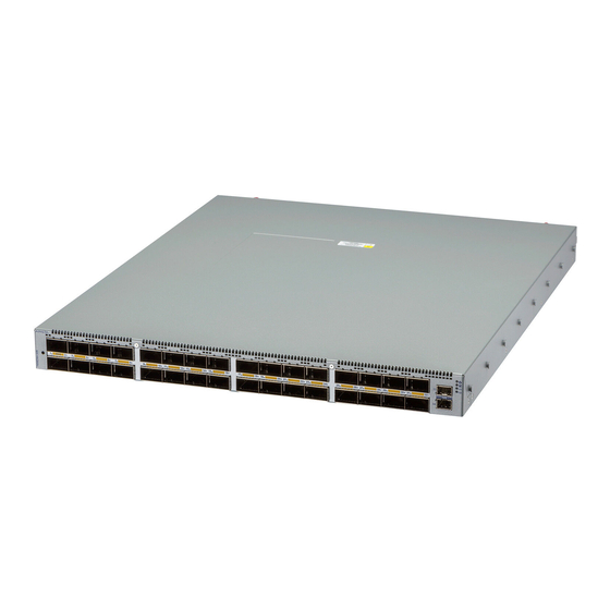
Summarization of Contents
Chapter 1: Overview
1.1 Scope
Covers the guide's scope, listing applicable Arista Networks Data Center Switches.
1.2 Receiving and Inspecting the Equipment
Details on how to receive and inspect the switch shipment for damage and completeness.
1.3 Installation Process
Outlines the sequential steps required to install and set up the switch.
1.4 Safety Information
Provides essential safety warnings and precautions for handling and installing the equipment.
1.5 Obtaining Technical Assistance
Information on how to contact Arista Networks support for technical assistance.
1.6 Specifications
Lists the technical specifications, including dimensions, weight, and environmental parameters.
Chapter 2: Preparation
2.1 Site Selection
Criteria for selecting a suitable site, considering temperature, ventilation, and airflow.
2.2 Tools and Parts Required for Installation
Lists the tools and parts needed for installing the switch, beyond the accessory kit.
2.3 Electrostatic Discharge (ESD) Precautions
Guidelines to prevent ESD damage during installation and servicing of the switch.
Chapter 3: Rack Mounting the Switch
3.1 Two-Post Rack Mount (1RU)
Instructions for mounting 1RU switches into a two-post equipment rack.
3.2 Four-Post Rack Mount (1RU)
Instructions for mounting 1RU switches into a four-post equipment rack.
3.3 Rack Mounting the Switch (2RU)
Overview of rack mounting procedures for 2RU switches.
3.4 Two-Post Rack Mount (2RU)
Notes that 2RU switches do not support two-post rack mounting.
3.5 Four-Post Rack Mount (2RU)
Instructions for mounting 2RU switches into a four-post equipment rack.
Chapter 4: Cabling the Switch
4.1 Grounding the Switch
Procedure for connecting the switch to the data center ground.
4.2 Grounding Adapter Assembly (1RU)
Step-by-step guide for assembling and attaching the 1RU grounding kit.
4.3 Grounding Adapter Assembly (2RU)
Step-by-step guide for assembling and attaching the 2RU grounding kit.
4.4 Connecting Power Cables
Instructions for connecting AC and DC power supplies to the switch.
4.5 Connecting Serial and Management Cables
Guidance on connecting console and Ethernet management cables.
Appendix A: Status Indicators
A.1 Front Indicators
Details the LEDs and indicators located on the front panel of the switch.
A.2 Rear Status Indicators
Describes the status LEDs for fan and power supply modules on the rear panel.
Appendix B: Parts List
B.1 Accessory Kits
Lists the components included in various accessory kits for switch mounting.
B.2 Cables
Lists the cables provided with the switch for installation purposes.
B.3 Ground Extender Kit (Optional)
Information regarding the optional ground extender kit for NEBS compliance.
Appendix E: Maintenance and Field Replacement
E.1 Considerations
Important points to consider before performing maintenance or replacing components.
E.2 Power Supplies
Procedures for removing and installing power supply modules in the switch.
E.3 Fan Modules
Procedures for removing and installing fan modules in the switch.


Need help?
Do you have a question about the DCS-7050DX4M-32S and is the answer not in the manual?
Questions and answers