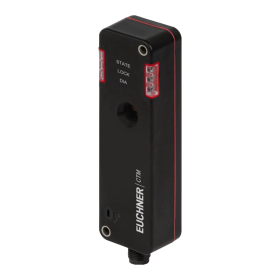
Summarization of Contents
1. About This Document
1.1. Scope and Validity
Defines the validity and scope of the operating instructions for the CTM-LBI-BP/BR series.
1.2. Target Audience
Identifies the intended audience for these operating instructions.
1.3. Symbol Key
Explains the meaning of symbols used throughout the document.
1.4. Related Documents
Lists other relevant documents for comprehensive user information.
6. Functionality
6.1. Bistable Guard Locking
Explains the bistable principle of the guard locking function.
6.2. Guard Lock Monitoring
Describes the two safe outputs for monitoring guard locking.
6.4. Guard Locking Control
Explains the guard locking mechanism and control via IMP.
6.5. Switching States
Details the switching states of the safety outputs, signals, and LEDs.
7. Manual Release
7.1. Auxiliary Release
Describes the auxiliary release mechanism to manually release guard locking.
9. Electrical Connection
9.1. UL/US Approval Notes
Provides important notes regarding UL/US approval and usage requirements.
9.2. Electrical Safety Considerations
Details safety considerations in case of faults in electrical connections.
9.3. Fuse Protection
Explains fuse protection requirements for the power supply.
9.5. Connector Assignments
Details the pin assignments for various connector types.
11. Series Connection
11.1. Control Cabinet Wiring
Describes series connection implementation using control cabinet wiring.
11.2. Y-Distributor Connection
Explains series connection using Y-distributors and pre-assembled cables.
11.2.1. Max Cable Lengths
Details maximum cable lengths for BR switch chains.
11.2.3. Y-Distributor Connector Assignment
Details Y-distributor connector assignment for series connection.
12. Communication Data
12.1. BR/IO-Link Gateway Connection
Explains connecting to a BR/IO-Link Gateway for data exchange.
12.2. Safety Relay Connection
Describes connecting to a safety relay with integrated BR/IO-Link Gateway.
12.3. Communication Data Overview
Provides an overview of cyclical and acyclical communication data.
12.3.2. Acyclical Data
Explains acyclical data (device data and events) that can be polled.
13. Setup
13.1. Teaching-in Actuator
Describes the process of teaching in an actuator for unicode evaluation.
13.2. Functional Checks
Outlines procedures for mechanical and electrical functional checks.
15. Status and Error Messages
15.1. LED Displays
Explains the meaning and colors of the device's LEDs.
15.2. Status Messages
Details device status based on LED indicators and signals.
15.3. Error Messages
Lists error codes, descriptions, and troubleshooting steps.
15.4. Acknowledging Error Messages
Explains how to acknowledge and reset error messages.
16. Technical Data
16.1. CTM-LBI Switch Specs
Provides detailed technical specifications for the CTM-LBI safety switch.
16.3. Dimension Drawings
Provides dimensional drawings and key measurements for the safety switch.
16.4. Actuator A-B-A1-A1- Specs
Details technical specifications for the A-B-A1-A1 actuator.
16.5. Actuator A-B-A5-A1- Specs
Details technical specifications for the A-B-A5-A1 actuator.


Need help?
Do you have a question about the CTM-LBI-BR Series and is the answer not in the manual?
Questions and answers