
Related Manuals for EUCHNER CTM-LBI-BR Unicode Series


Summary of Contents for EUCHNER CTM-LBI-BR Unicode Series
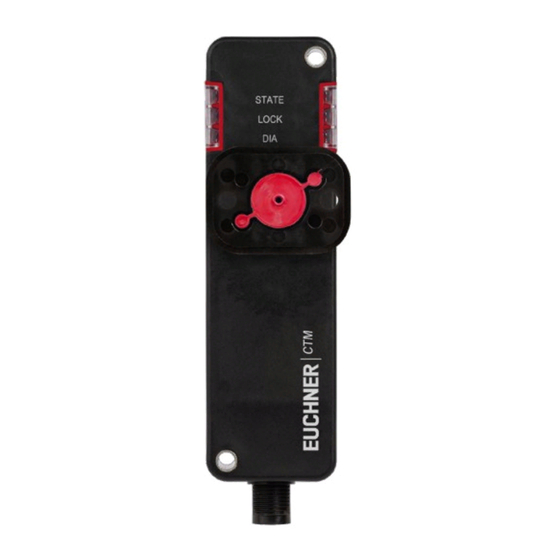
- Page 1 Operating Instructions Transponder-Coded Safety Switch With Guard Locking CTM-LBI-BR Unicode...
-
Page 2: Table Of Contents
Operating Instructions Transponder-Coded Safety Switch CTM-LBI-BR Contents About this document ..................... 4 1.1. Scope ............................4 1.2. Target group ..........................4 1.3. Key to symbols ..........................4 1.4. Supplementary documents ......................4 Correct use ......................5 Description of the safety function ................6 Exclusion of liability and warranty ................. 7 General safety precautions ................... - Page 3 Operating Instructions Transponder-Coded Safety Switch CTM-LBI-BR Setup ......................... 22 10.1. LED displays ..........................22 10.2. Teach-in function for actuator (only for unicode evaluation) ...............22 10.2.1. Actuator teach-in ......................22 10.3. Functional check ...........................23 10.3.1. Mechanical function test ....................23 10.3.2. Electrical function test ....................23 System status table ....................
-
Page 4: About This Document
Important! Always read all documents to gain a complete overview of safe installation, setup and use of the device. The documents can be downloaded from www.euchner.com. For this purpose enter the doc. no. in the search box. (Translation of the original operating instructions) 2525462-01-01/20... -
Page 5: Correct Use
Ì EN 60204-1 The safety switch is allowed to be operated only in conjunction with the intended EUCHNER actuator and the related connec- tion components from EUCHNER. On the use of different actuators or other connection components, EUCHNER provides no warranty for safe function. -
Page 6: Description Of The Safety Function
Operating Instructions Transponder-Coded Safety Switch CTM-LBI-BR 3. Description of the safety function Devices from this series feature the following safety functions: Monitoring of guard locking and the position of the guard (interlocking device with guard locking according to EN ISO 14119) Ì Safety function (see chapter 6.7. -
Page 7: Exclusion Of Liability And Warranty
Prior to use, read the operating instructions and keep these in a safe place. Ensure the operating instructions are always available during mounting, setup and servicing. For this reason you should archive a printed copy of the operating instructions. You can download the operating instructions from www.euchner.com. 2525462-01-01/20 (Translation of the original operating instructions) -
Page 8: Function
Operating Instructions Transponder-Coded Safety Switch CTM-LBI-BR 6. Function The device permits the locking of movable guards. Safety switch The system consists of the following components: coded actuator (transponder) and switch. Transponder-coded actuator Whether the device learns the complete actuator code (unicode) or not (multicode) depends on the respective version. -
Page 9: Guard Locking On Version Ctm-Lbi
Operating Instructions Transponder-Coded Safety Switch CTM-LBI-BR 6.6. Guard locking on version CTM-LBI (guard locking actuated by spring force and released by power-ON) Activating guard locking: close guard; no voltage at control input IMP. Releasing guard locking: apply voltage to control input IMP. The spring-operated guard locking functions in accordance with the closed-circuit current principle. -
Page 10: Manual Release
Operating Instructions Transponder-Coded Safety Switch CTM-LBI-BR 7. Manual release Important! Ì All release functions latch when the device is electrically isolated. Ì Guard locking remains released when the release function is reset. Some situations require the guard locking to be released manually (e.g. malfunctions or an emergency). A function test should be performed after release. -
Page 11: Mounting
Operating Instructions Transponder-Coded Safety Switch CTM-LBI-BR 8. Mounting CAUTION Safety switches must not be bypassed (bridging of contacts), turned away, removed or otherwise rendered ineffective. Ì Observe EN ISO 14119:2013, section 7, for information about reducing the possibilities for by- passing an interlocking device. NOTICE Risk of damage to equipment and malfunctions as a result of incorrect installation. -
Page 12: Electrical Connection
Operating Instructions Transponder-Coded Safety Switch CTM-LBI-BR 9. Electrical connection The following connection options are available: Ì Separate operation Ì Series connection with Y-distributors Ì Series connection, e.g. with wiring in the control cabinet. WARNING In the event of a fault, loss of the safety function due to incorrect connection. Ì... -
Page 13: Notes About
Operating Instructions Transponder-Coded Safety Switch CTM-LBI-BR 9.1. Notes about Important! Ì For use and operation as per the requirements , a power supply with the feature “for use in Class 2 circuits” must be used. Alternative solutions must comply with the following requirements: Electrically isolated power supply unit in combination with fuse as per UL248. -
Page 14: Requirements For Connecting Cables
Ì On the use of other connection components, the requirements in the following table apply. EUCHNER provides no warranty for safe function in case of failure to comply with these require- ments. Observe the following requirements with respect to the connecting cables: For safety switch CTM-…-BR-…-SA-…... -
Page 15: Maximum Cable Lengths
Possible output current per channel FO1A/FO1B Max. cable length from the last switch to the control system 0.34 mm² Contact EUCHNER in the following cases: Ì If you connect more than 3 switches in series. Ì If you plan to use a different cable design (cross-section, material, etc.). -
Page 16: Connector Assignment, Safety Switch Ctm
Safety output, channel 1 FO1B Safety output, channel 2 OD/C Door monitoring output/communication FI1A Enable input, channel 1 0 V Operating voltage, 0 V Control input of guard locking solenoid 1) Only for standard EUCHNER connecting cable. (Translation of the original operating instructions) 2525462-01-01/20... -
Page 17: Connector Assignment, Y-Distributor For Series Connection Without Br Evaluation Unit
Operating Instructions Transponder-Coded Safety Switch CTM-LBI-BR 9.7. Connector assignment, Y-distributor for series connection without BR evaluation unit Connector assignment of safety switch CTM-LBI-BR (8-pin plug) and Y-distributor (8-pin socket) Function Important! X1.1 FI1B X1.2 All guard locking solenoids are always X1.3 FO1A controlled simultaneously on the use of... -
Page 18: Connector Assignment, Y-Distributor For Series Connection To A Br Evaluation Unit
Operating Instructions Transponder-Coded Safety Switch CTM-LBI-BR 9.8. Connector assignment, Y-distributor for series connection to a BR evaluation unit Connector assignment of safety switch CTM-LBI-BR (8-pin plug) and Y-distributor (8-pin socket) Function X1.1 FI1B X1.2 X1.3 FO1A X1.4 FO1B X1.5 OD/C X1.6 FI1A X1.7... -
Page 19: Connection Of Several Devices In A Switch Chain Without Br Evaluation Unit
The user is responsible for safe inte- gration into the overall system. Detailed application examples can be found at www.euchner.com. Simply enter the order number of your switch in the search box. You will find all available connec- tion examples for the device in Downloads. - Page 20 Operating Instructions Transponder-Coded Safety Switch CTM-LBI-BR Figure 1: Connection example for series connection (Translation of the original operating instructions) 2525462-01-01/20...
-
Page 21: Notes On Operation With Safe Control Systems
Ì Always connect inputs FI1A and FI1B directly to a power supply unit or to outputs FO1A and FO1B of another EUCHNER BR device (series connection). Pulsed signals must not be present at inputs FI1A and FI1B. -
Page 22: Setup
Operating Instructions Transponder-Coded Safety Switch CTM-LBI-BR 10. Setup 10.1. LED displays You will find a detailed description of the signal functions in chapter 11. System status table on page 24. Color STATE green LOCK yellow STATE LOCK 10.2. Teach-in function for actuator (only for unicode evaluation) The actuator must be allocated to the safety switch using a teach-in function before the system forms a functional unit. -
Page 23: Functional Check
Operating Instructions Transponder-Coded Safety Switch CTM-LBI-BR 10.3. Functional check WARNING Danger of fatal injury as a result of faults in installation and functional check. Ì Before carrying out the functional check, make sure that there are no persons in the danger zone. Ì... -
Page 24: System Status Table
Operating Instructions Transponder-Coded Safety Switch CTM-LBI-BR 11. System status table LED indicator Output Operating mode State 5 Hz Power Up closed Normal operation, door closed and locked 1 x in- Normal operation closed Normal operation, door closed and not locked verse open Normal operation, door open open... - Page 25 Operating Instructions Transponder-Coded Safety Switch CTM-LBI-BR After the cause has been remedied, faults can generally be reset by opening and closing the guard (when DIA flashes inversely once). Otherwise, briefly disconnect the power supply. Please contact the manufacturer if the fault could not be reset after restarting.
-
Page 26: Technical Data
Operating Instructions Transponder-Coded Safety Switch CTM-LBI-BR 12. Technical data NOTICE If a data sheet is included with the product, the information on the data sheet applies. 12.1. Technical data for safety switch CTM-LBI-BR Parameter Value Unit min. typ. max. General Material - Seals Fluorinated rubber (FKM) -
Page 27: Typical System Times
Operating Instructions Transponder-Coded Safety Switch CTM-LBI-BR 12.1.1. Typical system times Please refer to the technical data for the exact values. Ready delay: After switch-on, the device carries out a self-test. The system is ready for operation only after this time. Turn-on time of safety outputs: The max. -
Page 28: Radio Frequency Approvals
CTM-L2-BP series CTM-I2-BP series CTM-L2-AS1B series CTM-I2-AS1B series CTM-LBI-AS1B series CTM-IBI-AS1B series Responsible Party – U.S. Contact Information EUCHNER USA Inc. 6723 Lyons Street East Syracuse, NY 13057 +1 315 701-0315 +1 315 701-0319 info(at)euchner-usa.com http://www.euchner-usa.com (Translation of the original operating instructions) 2525462-01-01/20... -
Page 29: Dimension Drawing For Safety Switch Ctm
Operating Instructions Transponder-Coded Safety Switch CTM-LBI-BR 12.3. Dimension drawing for safety switch CTM… ∅ 4.5 (2x) Necessary minimum travel + permissible overtravel For M4 screw Approach direction Horizontal (h) 18 + 2 LEDs Auxiliary release (optional) M12x1 Min. door radius [mm] 2525462-01-01/20 (Translation of the original operating instructions) -
Page 30: Technical Data For Actuator A-B-A1-A1
Operating Instructions Transponder-Coded Safety Switch CTM-LBI-BR 12.4. Technical data for actuator A-B-A1-A1-… Value Parameter Unit min. typ. max. Material - Housing Ultradur black - Ball holder Stainless steel - Elastomer A-B-A1-161642: FKM red / A-B-A1-161643: FKM blue Resistance Resistant to chemicals and oil Food safe DIN EN 1672-2, DIN EN ISO 14159, PAH category 3 Weight... -
Page 31: Ordering Information And Accessories
13. Ordering information and accessories Tip! Suitable accessories, e.g. cables or assembly material, can be found at www.euchner.com. To order, enter the order number of your item in the search box and open the item view. Accessories that can be combined with the item are listed in “Accessories.”... -
Page 32: Declaration Of Conformity
Operating Instructions Transponder-Coded Safety Switch CTM-LBI-BR 16. Declaration of conformity (Translation of the original operating instructions) 2525462-01-01/20... - Page 33 Operating Instructions Transponder-Coded Safety Switch CTM-LBI-BR 2525462-01-01/20 (Translation of the original operating instructions)
- Page 34 Operating Instructions Transponder-Coded Safety Switch CTM-LBI-BR (Translation of the original operating instructions) 2525462-01-01/20...
- Page 35 Operating Instructions Transponder-Coded Safety Switch CTM-LBI-BR 2525462-01-01/20 (Translation of the original operating instructions)
- Page 36 Edition: 2525462-01-01/20 Title: Operating Instructions Transponder-Coded Safety Switch CTM-LBI-BR (Translation of the original operating instructions) Copyright: © EUCHNER GmbH + Co. KG, 01/2020 Subject to technical modifications; no responsibility is accept- ed for the accuracy of this information.
Need help?
Do you have a question about the CTM-LBI-BR Unicode Series and is the answer not in the manual?
Questions and answers