
Related Manuals for EUCHNER CTM-C2-BP


Summary of Contents for EUCHNER CTM-C2-BP
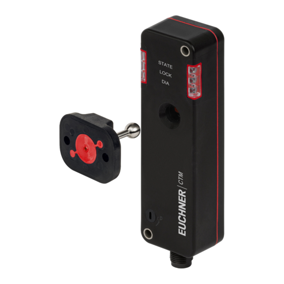
- Page 1 Operating Instructions Transponder-Coded Safety Switch with Guard Locking CTM-C2-BP/BR-FLX High/Low Coding Level...
-
Page 2: Table Of Contents
Operating Instructions Transponder-Coded Safety Switch CTM-C2-BP/BR-FLX Contents About this document ..................... 4 1.1. Scope ............................4 1.2. Target group ..........................4 1.3. Key to symbols ..........................4 1.4. Supplementary documents ......................4 Correct use ......................5 Description of the safety function ................7 Exclusion of liability and warranty ................. 8 General safety precautions ................... - Page 3 Status messages ..........................31 15.3. Error messages ..........................32 15.4. Acknowledging error messages .....................33 Technical data ....................34 16.1. Technical data for safety switch CTM-C2-BP/BR ................34 16.1.1. Typical system times ......................35 16.2. Radio frequency approvals......................36 16.3. Dimension drawing for safety switch CTM… ...................37 16.4.
-
Page 4: About This Document
1. About this document 1.1. Scope These operating instructions are valid for all safety switches CTM-C2-BP/BR-..-FLX version V1.2.X. These operating instruc- tions, the document Safety information and any available data sheet form the complete user information for your device. 1.2. -
Page 5: Correct Use
Operating Instructions Transponder-Coded Safety Switch CTM-C2-BP/BR-FLX 2. Correct use Safety switches series CTM-C2-… are interlocking devices with guard locking solenoid (type 4). The device complies with the requirements according to EN IEC 60947-5-3. Devices with high coding level evaluation (HC) possess a high coding level, devices with low coding level evaluation (LC) possess a low coding level. - Page 6 Transponder-Coded Safety Switch CTM-C2-BP/BR-FLX The safety switch is allowed to be operated only in conjunction with the intended EUCHNER actuators and the related con- nection components from EUCHNER. On the use of different actuators or other connection components, EUCHNER provides no warranty for safe function.
-
Page 7: Description Of The Safety Function
Operating Instructions Transponder-Coded Safety Switch CTM-C2-BP/BR-FLX 3. Description of the safety function Devices from this series feature the following safety functions: The following applies to active guard lock monitoring: Monitoring of guard locking and the position of the guard (interlocking device with guard locking according to EN ISO 14119) Ì... -
Page 8: Exclusion Of Liability And Warranty
Operating Instructions Transponder-Coded Safety Switch CTM-C2-BP/BR-FLX 4. Exclusion of liability and warranty In case of failure to comply with the conditions for correct use stated above, or if the safety regulations are not followed, or if any servicing is not performed as required, liability will be excluded and the warranty void. -
Page 9: Function
Operating Instructions Transponder-Coded Safety Switch CTM-C2-BP/BR-FLX 6. Function The device permits the locking of movable guards. Safety switch The system consists of the following components: coded actuator (transponder) and switch. Transponder-coded actuator Whether the device learns the complete actuator code (HC) or not (LC) depends on the respective version. -
Page 10: Guard Locking Signal Ol
Operating Instructions Transponder-Coded Safety Switch CTM-C2-BP/BR-FLX 6.2.3. Guard locking signal OL The guard locking signal is present if the guard locking is active. 6.2.4. Status signal OM The status signal is present if the device’s safety outputs are switched. 6.2.5. Locking element signal OLS The locking element signal is present if the locking element is stuck and it is therefore not possible to activate/deactivate guard locking. -
Page 11: Switching States
Operating Instructions Transponder-Coded Safety Switch CTM-C2-BP/BR-FLX 6.4. Switching states The detailed switching states for your switch can be found in chapter 15. Status and error messages on page 30. All safety outputs, signals and display LEDs are described there. 6.4.1. Switching states with control via the control input IMP... -
Page 12: Manual Release
Operating Instructions Transponder-Coded Safety Switch CTM-C2-BP/BR-FLX 7. Manual release Important! Ì All release functions latch when the device is electrically isolated. Ì Guard locking remains released when the release function is reset. Some situations require the guard locking to be released manually (e.g. malfunctions or an emergency). A function test must be performed after release. -
Page 13: Mounting
Operating Instructions Transponder-Coded Safety Switch CTM-C2-BP/BR-FLX 8. Mounting CAUTION Safety switches must not be bypassed (bridging of contacts), turned away, removed or otherwise rendered ineffective. Ì Observe EN ISO 14119:2013, section 7, for information about reducing the possibilities for bypassing an interlocking device. -
Page 14: Electrical Connection
Operating Instructions Transponder-Coded Safety Switch CTM-C2-BP/BR-FLX 9. Electrical connection The following connection options are available: Ì Separate operation Ì Series connection with wiring in the control cabinet Ì Series connection with Y-distributors Ì Connection without IO-Link communication Ì Connection with IO-Link communication WARNING In the event of a fault, loss of the safety function due to incorrect connection. -
Page 15: Notes About
Operating Instructions Transponder-Coded Safety Switch CTM-C2-BP/BR-FLX 9.1. Notes about Important! Ì This device is intended to be used with a Class 2 power source in accordance with UL1310. As an alternative an LV/C (Limited Voltage/Current) power source with the following properties can... -
Page 16: Requirements For Connecting Cables
Use connection components and connecting cables from EUCHNER. Ì On the use of other connection components, the requirements in the following table apply. EUCHNER provides no warranty for safe function in case of failure to comply with these requirements. Observe the following requirements with respect to the connecting cables: For safety switch CTM-…-BP-…-SA-…... -
Page 17: Notes On Operation With Safe Control Systems
With series connection: always connect inputs FI1A and FI1B directly to a power supply unit or to outputs FO1A and FO1B of another EUCHNER BR device. Pulsed signals must not be present at inputs FI1A and FI1B. A detailed example of connecting and setting the parameters of the control system is available for many devices at www.euchner.com, in the area Service/Downloads/Applications/CTM. -
Page 18: Connection Of A Single Ctm-Bp/Br (Separate Operation)
The user is responsible for safe integration into the overall system. Detailed application examples can be found at www.euchner.com. Simply enter the order number of your switch in the search box. You will find all available connection examples for the device in Downloads. -
Page 19: Connection Of Several Devices In A Chain (Series Connection)
The user is responsible for safe integration into the overall system. Detailed application examples can be found at www.euchner.com. Simply enter the order number of your switch in the search box. You will find all available connection exam- ples for the device in Downloads. -
Page 20: Maximum Cable Lengths With Br Switch Chains
Operating Instructions Transponder-Coded Safety Switch CTM-C2-BP/BR-FLX 11.2.1. Maximum cable lengths with BR switch chains Important! The maximum number of switches in a BR switch chain depends on many factors, including the cable length. This case example shows a standard application. You will find further connection examples at www.euchner.com. -
Page 21: Connector Assignment Of Y-Distributor For Series Connection Without Io-Link Communication
Operating Instructions Transponder-Coded Safety Switch CTM-C2-BP/BR-FLX 11.2.3. Connector assignment of Y-distributor for series connection without IO-Link communication Important! Ì The switch chain must always be terminated with strapping plug 097645. Ì All guard locking solenoids are always controlled simultaneously on the use of these Y-distributors in a series connection. - Page 22 Operating Instructions Transponder-Coded Safety Switch CTM-C2-BP/BR-FLX Fig. 2: Connection example for series connection with control of guard locking via the control input IMP (translation of the original operating instructions) MAN20001574-01-09/22...
-
Page 23: Connector Assignment Of Y-Distributor For Series Connection With Io-Link Communication
Operating Instructions Transponder-Coded Safety Switch CTM-C2-BP/BR-FLX 11.2.4. Connector assignment of Y-distributor for series connection with IO-Link communication Important! Ì These Y-distributors can be used only with device variants that control guard locking via IO-Link communication. Ì The switch chain must always be terminated with strapping plug 097645. -
Page 24: Using Communication Data
Operating Instructions Transponder-Coded Safety Switch CTM-C2-BP/BR-FLX 12. Using communication data A BR/IO-Link Gateway is required to use the device’s communication data and forward them to a higher-level bus system. The following devices are suitable: Ì GWY-CB-1-BR-IO (BR/IO-Link Gateway) Ì ESM-CB (safety relay with integrated BR/IO-Link Gateway) 12.1. -
Page 25: Overview Of The Communication Data
Operating Instructions Transponder-Coded Safety Switch CTM-C2-BP/BR-FLX 12.3. Overview of the communication data The switch transmits both process data that are continuously transmitted to the evaluation unit (cyclical data) and data that can be polled specifically as needed (acyclical data). For further information on connection and on the communication data, refer to the operating instructions for your BR/IO-Link Gateway. -
Page 26: Acyclical Data (Device Data And Events)
Operating Instructions Transponder-Coded Safety Switch CTM-C2-BP/BR-FLX 12.3.2. Acyclical data (device data and events) After one of the commands listed below is sent, the requested data are provided via the IO-Link Gateway. The reply message always consists of 8 bytes in big endian format. -
Page 27: Setup
Operating Instructions Transponder-Coded Safety Switch CTM-C2-BP/BR-FLX 13. Setup 13.1. Configuring device The device must be configured and the actuator must be allocated to the safety switch before the system forms a functional unit. The guard lock monitoring is activated or deactivated with the aid of a function actuator during configuration. -
Page 28: Functional Check
Operating Instructions Transponder-Coded Safety Switch CTM-C2-BP/BR-FLX 1. Establish teach-in standby: - Devices in the condition as supplied: unlimited teach-in standby after switching on. - Switch already taught-in: teach-in standby is available for approx. 3 min after switching on. Teach-in standby indication, STATE LED flashes 3x repeatedly. -
Page 29: Factory Reset
Operating Instructions Transponder-Coded Safety Switch CTM-C2-BP/BR-FLX With inactive guard lock monitoring: 1. Switch on operating voltage. The machine must not start automatically. ¨ The safety switch carries out a self-test. The green STATE LED then flashes at regular intervals. ¨... -
Page 30: Status And Error Messages
Operating Instructions Transponder-Coded Safety Switch CTM-C2-BP/BR-FLX 15. Status and error messages 15.1. LED displays Color STATE green LOCK yellow STATE LOCK Important! If you do not find the displayed device status in the following tables, this indicates an internal device fault. -
Page 31: Status Messages
Operating Instructions Transponder-Coded Safety Switch CTM-C2-BP/BR-FLX 15.2. Status messages LED indicator Safety Door Guard outputs position locking Status STATE LOCK FO1A / signal signal OL green yellow FO1B Self-test after operating voltage is switched on. 5 Hz (5 s) No communication with the BR/IO-Link Gateway. -
Page 32: Error Messages
Operating Instructions Transponder-Coded Safety Switch CTM-C2-BP/BR-FLX 15.3. Error messages knowl- LED indicator edging errors Error Troubleshooting STATE LOCK green yellow Teach-in error Actuator removed from the actuating range prior to Check whether the actuator is outside the actuating 0x1F the end of the teach-in operation. -
Page 33: Acknowledging Error Messages
Operating Instructions Transponder-Coded Safety Switch CTM-C2-BP/BR-FLX knowl- LED indicator edging errors Error Troubleshooting STATE LOCK green yellow Plausibility error Transponder is no longer detected when guard lock- Check actuator and replace it if necessary. 0x89 ing is active. Actuator defective or malfunctioning. -
Page 34: Technical Data
Operating Instructions Transponder-Coded Safety Switch CTM-C2-BP/BR-FLX 16. Technical data NOTICE If a data sheet is available for the product, the information on the data sheet applies. 16.1. Technical data for safety switch CTM-C2-BP/BR Value Parameter Unit min. typ. max. General... -
Page 35: Typical System Times
Operating Instructions Transponder-Coded Safety Switch CTM-C2-BP/BR-FLX Value Parameter Unit min. typ. max. Reliability values acc. to EN ISO 13849-1 Guard lock monitoring Control of guard locking Category Performance Level (PL) PL e PL d 4.52 x 10 1.03 x 10 Mission time years 1) For devices with connecting cable, the following applies: in areas where high-pressure cleaners are used, make sure the high-pressure cleaning jet does not act directly on the connecting cable or the cable entry into the device. -
Page 36: Radio Frequency Approvals
Operating Instructions Transponder-Coded Safety Switch CTM-C2-BP/BR-FLX 16.2. Radio frequency approvals FCC ID: 2AJ58-07 22052-07 FCC/IC-Requirements This device complies with part 15 of the FCC Rules and with Industry Canada’s licence-exempt RSSs. Operation is subject to the following two conditions: 1) This device may not cause harmful interference, and 2) this device must accept any interference received, including interference that may cause undesired operation. -
Page 37: Dimension Drawing For Safety Switch Ctm
Operating Instructions Transponder-Coded Safety Switch CTM-C2-BP/BR-FLX 16.3. Dimension drawing for safety switch CTM… Necessary minimum travel + perm. overtravel Approach direction Horizontal (h) 21 + 2 ∅ 4.5 (2x) For M4 screw LEDs Auxiliary release (optional) Center offset m = ± 2 mm max. M12x1 Min. -
Page 38: Technical Data For Actuator A-Flx-B-0.-A1-A1
Operating Instructions Transponder-Coded Safety Switch CTM-C2-BP/BR-FLX 16.4. Technical data for actuator A-FLX-B-0.-A1-A1-… Value Parameter Unit min. typ. max. Material - Housing Ultradur black - Ball holder Stainless steel - Elastomer Resistance Resistant to chemicals and oil Food safe DIN EN 1672-2, DIN EN ISO 14159, PAH category 3 Weight 0.0194... -
Page 39: Ordering Information And Accessories
20. Declaration of conformity The declaration of conformity is part of the operating instructions. The complete EU declaration of conformity can also be found at www.euchner.com. Enter the order number of your device in the search box. The document is available under Downloads. - Page 40 Edition: MAN20001574-01-09/22 Title: Operating Instructions Transponder-Coded Safety Switch CTM-C2-BP/BR-FLX (translation of the original operating instructions) Copyright: © EUCHNER GmbH + Co. KG, 09/2022 Subject to technical modifications; no responsibility is accept- ed for the accuracy of this information.
Need help?
Do you have a question about the CTM-C2-BP and is the answer not in the manual?
Questions and answers