
Related Manuals for EUCHNER CTP-L AS Series


Summary of Contents for EUCHNER CTP-L AS Series
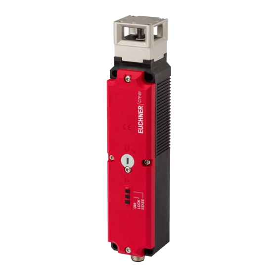
- Page 1 Operating Instructions Transponder-Coded Safety Switch with Guard Locking CTP-L.-AS Unicode/Multicode...
-
Page 2: Table Of Contents
Operating Instructions Transponder-Coded Safety Switch CTP-L.-AS Contents About this document ..................... 4 1.1. Scope ............................4 1.2. Target group ..........................4 1.3. Key to symbols ..........................4 1.4. Supplementary documents ......................4 Correct use ......................5 Description of the safety function ................6 Exclusion of liability and warranty ................. 7 General safety precautions ................... - Page 3 Operating Instructions Transponder-Coded Safety Switch CTP-L.-AS Setup ......................... 18 11.1. LED displays ..........................18 11.2. Teaching-in actuator (only for unicode evaluation) ................18 11.3. Functional check ...........................19 11.3.1. Mechanical function test ....................19 11.3.2. Electrical function test ....................19 System status table .................... 20 Technical data ....................
-
Page 4: About This Document
Important! Always read all documents to gain a complete overview of safe installation, setup and use of the device. The documents can be downloaded from www.euchner.com. For this purpose enter the doc. no. in the search box. (translation of the original operating instructions) 2124662-07-05/23... -
Page 5: Correct Use
EN 60204-1 Ì The safety switch is allowed to be operated only in conjunction with the intended EUCHNER actuator and the related connec- tion components from EUCHNER. On the use of different actuators or other connection components, EUCHNER provides no warranty for safe function. -
Page 6: Description Of The Safety Function
Operating Instructions Transponder-Coded Safety Switch CTP-L.-AS 3. Description of the safety function Devices from this series feature the following safety functions: Monitoring of guard locking and the position of the guard (interlocking device with guard locking according to EN ISO 14119) Safety function (see chapter 6.3. Switching states on page 9): Ì... -
Page 7: Exclusion Of Liability And Warranty
Prior to use, read the operating instructions and keep these in a safe place. Ensure the operating instructions are always available during mounting, setup and servicing. For this reason you should archive a printed copy of the operating instructions. You can download the operating instructions from www.euchner.com. 2124662-07-05/23 (translation of the original operating instructions) -
Page 8: Function
Operating Instructions Transponder-Coded Safety Switch CTP-L.-AS 6. Function The device permits the locking of movable guards. Transponder-coded actuator The system consists of the following components: coded actuator (transponder) and switch. Whether the device learns the complete actuator code (unicode) or not (multi- code) depends on the respective version. -
Page 9: Guard Locking On Version Ctp-L2
Operating Instructions Transponder-Coded Safety Switch CTP-L.-AS 6.2. Guard locking on version CTP-L2 (guard locking actuated by power-ON and released by spring force) Important! Guard locking devices according to the open-circuit current principle are not intended for protecting Ì personnel. Use as guard locking for personnel protection is possible only in special cases, after strict assessment Ì... -
Page 10: Manual Release
Operating Instructions Transponder-Coded Safety Switch CTP-L.-AS 7. Manual release Some situations require the guard locking to be released manually (e.g. malfunctions or an emergency). A function test must be performed after release. More information on this topic can be found in the standard EN ISO 14119:2013, section 5.7.5.1. The device can feature the following release functions: 7.1. -
Page 11: Actuating Auxiliary Key Release
Operating Instructions Transponder-Coded Safety Switch CTP-L.-AS 7.1.2. Actuating auxiliary key release On devices with auxiliary key release (can be retrofitted), simply turn the key to release. Function as for auxiliary release. For mounting, see the auxiliary key release supplement. 7.2. Emergency release This permits opening of a locked guard from outside the danger zone without tools. -
Page 12: Escape Release (Optional)
Operating Instructions Transponder-Coded Safety Switch CTP-L.-AS 7.3. Escape release (optional) This permits opening of a locked guard from the danger zone without tools (see chapter 13.2. Dimension drawing for safety switch CTP… on page 22). Important! It must be possible to actuate the escape release manually from inside Ì... -
Page 13: Wire Front Release (Bowden)
Operating Instructions Transponder-Coded Safety Switch CTP-L.-AS 7.4. Wire front release (bowden) Release via a pull wire. Depending on the type of attachment, the wire front release can be used as an emergency release or escape release. The following applies to non-latching wire front releases. If the release is to be used as an emergency release, one of the following measures must be taken (see EN ISO 14119:2013, section 5.7.5.3): Install the release so that it can be reset only with the aid of a tool. -
Page 14: Changing The Approach Direction
Operating Instructions Transponder-Coded Safety Switch CTP-L.-AS 8. Changing the approach direction The approach direction needs to be changed only if the switch is to be approached from the rear. Proceed as follows: 1. Remove the screws from the safety switch. 2. -
Page 15: Mounting
Operating Instructions Transponder-Coded Safety Switch CTP-L.-AS 9. Mounting CAUTION Safety switches must not be bypassed (bridging of contacts), turned away, removed or otherwise rendered ineffective. Observe EN ISO 14119:2013, section 7, for information about reducing the possibilities for bypassing Ì an interlocking device. NOTICE Risk of damage to equipment and malfunctions as a result of incorrect installation. -
Page 16: Electrical Connection
Operating Instructions Transponder-Coded Safety Switch CTP-L.-AS 10. Electrical connection View of safety switch plug connector 1 AS-Interface + 2 Auxiliary voltage, 0 V 3 AS-Interface - 4 Auxiliary voltage, 24 V Fig. 3: Terminal assignment, AS-Interface M12 plug connector 10.1. Notes about Important! This device is intended to be used with a Class 2 power source in accordance with UL1310. -
Page 17: As-Interface Status Messages
Operating Instructions Transponder-Coded Safety Switch CTP-L.-AS 10.4. AS-Interface status messages A dual LED (red/green) displays the colors red, green and yellow. The following table provides assistance with troubleshooting. State Explanation ASI LED Green Normal operation No data exchange between master and slave Cause: - Master in STOP mode - Slave not in LPS... -
Page 18: Setup
Operating Instructions Transponder-Coded Safety Switch CTP-L.-AS 11. Setup 11.1. LED displays You will find a detailed description of the signal functions in chapter 12. System status table on page 20. Color Green/red STATE Green LOCK/DIA Yellow/red STATE LOCK/DIA 11.2. Teaching-in actuator (only for unicode evaluation) The actuator must be allocated to the safety switch using a teach-in function before the system forms a functional unit. -
Page 19: Functional Check
Operating Instructions Transponder-Coded Safety Switch CTP-L.-AS 11.3. Functional check WARNING Danger of fatal injury as a result of faults in installation and the functional check. Before carrying out the functional check, make sure that there are no persons in the danger zone. Ì... -
Page 20: System Status Table
Operating Instructions Transponder-Coded Safety Switch CTP-L.-AS 12. System status table The dual LOCK/DIA LED displays the colors red and yellow. Depending on the state, both colors can flash alternately. LED indicator Output Operating mode State closed Normal operation, door closed and locked 1 x ... -
Page 21: Technical Data
Operating Instructions Transponder-Coded Safety Switch CTP-L.-AS 13. Technical data NOTICE If a data sheet is available for the product, the information on the data sheet applies. 13.1. Technical data for safety switch CTP-AS Value Parameter Unit min. typ. max. General Material - Switch head Die-cast zinc... -
Page 22: Typical System Times
Operating Instructions Transponder-Coded Safety Switch CTP-L.-AS 13.1.1. Typical system times Refer to the technical data for the exact values. Ready delay: After switch-on, the device carries out a self-test. The system is ready for operation only after this time. Turn-on time of safety outputs: The max. reaction time t is the time from the moment when the guard is locked to the moment when the safety outputs switch on. -
Page 23: Dimension Drawing For Product Version V1.2.X
Operating Instructions Transponder-Coded Safety Switch CTP-L.-AS 13.2.2. Dimension drawing for product version V1.2.X Ø 5.3 (4x) for screw M5x35 mm DIN 1207/ISO 4762 Auxiliary release Locking screw LEDs M12x1 <42> <40> Cable outlet C Cable outlet A 2124662-07-05/23 (translation of the original operating instructions) -
Page 24: Dimension Drawing For Variants Ctp
Operating Instructions Transponder-Coded Safety Switch CTP-L.-AS 13.2.3. Dimension drawing for variants CTP… With escape release The actuator shaft for the escape release can be extended using extensions (max. 94 mm) ≈ 5 Basic position for escape release 44 / 74 / 94 Release by pressing With auxiliary key release With auxiliary release... -
Page 25: Technical Data For Actuator Ctp
Operating Instructions Transponder-Coded Safety Switch CTP-L.-AS 13.3. Technical data for actuator CTP-... Value Parameter Unit min. typ. max. Housing material Fiber reinforced plastic Weight 0.03 … 0.06 (depending on version) Ambient temperature °C Degree of protection IP65/IP67/IP69/IP69K Mechanical life 1 x 10 Locking force, max. (ISO 14119) - Straight actuator 3,900... - Page 26 Operating Instructions Transponder-Coded Safety Switch CTP-L.-AS Dimension drawing Min. door radius [mm] Order no./item 37,5 122667 A-C-H-W-SST-122667 12,45 A-A 1 : 2 37,2 122668 A-C-H-W-SST-122668 5,25 (translation of the original operating instructions) 2124662-07-05/23...
- Page 27 Operating Instructions Transponder-Coded Safety Switch CTP-L.-AS Dimension drawing Min. door radius [mm] Order no./item 3,25 122671 A-C-H-RL-LS-122671 max. 28 X = 53 mm (122671, 122672) X = 49 mm (122669, 122670) 122672 A-C-H-RR-LS-122672 122675 A-C-H-RO-LS-122675 max. 28 X = 41 mm (122673, 122674) X = 45 mm (122675, 122676) 13,2 X = 41 mm (122673, 122674)
-
Page 28: Ordering Information And Accessories
17. Declaration of conformity The declaration of conformity is part of the operating instructions. The complete EU declaration of conformity can also be found at www.euchner.com. Enter the order number of your device in the search box. The document is available under Downloads. - Page 29 Operating Instructions Transponder-Coded Safety Switch CTP-L.-AS 2124662-07-05/23 (translation of the original operating instructions)
- Page 30 Edition: 2124662-07-05/23 Title: Operating Instructions Transponder-Coded Safety Switch CTP-L.-AS (translation of the original operating instructions) Copyright: © EUCHNER GmbH + Co. KG, 05/2023 Subject to technical modifications; no responsibility is accept- ed for the accuracy of this information.
Need help?
Do you have a question about the CTP-L AS Series and is the answer not in the manual?
Questions and answers