
Subscribe to Our Youtube Channel
Related Manuals for EUCHNER CTM-CBI-BP


Summary of Contents for EUCHNER CTM-CBI-BP
- Page 1 Operating Instructions Transponder-Coded Safety Switch With Guard Locking CTM-CBI-BP Unicode/Multicode...
-
Page 2: Table Of Contents
Operating Instructions Transponder-Coded Safety Switch CTM-CBI-BP Contents About this document ..................... 4 1.1. Scope ............................4 1.2. Target group ..........................4 1.3. Key to symbols ..........................4 1.4. Supplementary documents ......................4 Correct use ......................5 Description of the safety function ................7 Exclusion of liability and warranty ................. 8 General safety precautions ................... - Page 3 Operating Instructions Transponder-Coded Safety Switch CTM-CBI-BP 9.7. Notes on operation with safe control systems .................19 Setup ......................... 20 10.1. Device configuration and teach-in operation ..................20 10.1.1. Configuring actuator ......................20 10.2. LED displays ..........................20 10.3. Functional check ...........................21 10.3.1. Mechanical function test ....................21 10.3.2.
-
Page 4: About This Document
1. About this document 1.1. Scope These operating instructions are valid for all CTM-CBI-BP… from version V1.0.0. These operating instructions, the document Safety information and any enclosed data sheet form the complete user information for your device. Series Guard lock monitoring types Product versions from V1.0.0... -
Page 5: Correct Use
Ì EN 60204-1 The safety switch is allowed to be operated only in conjunction with the intended EUCHNER actuators and the related con- nection components from EUCHNER. On the use of different actuators or other connection components, EUCHNER provides no warranty for safe function. - Page 6 Operating Instructions Transponder-Coded Safety Switch CTM-CBI-BP Table 1: Possible combinations for CTM components Actuator Safety switch S-B-0.-A1... CTM-… Unicode/Multicode Key to symbols Combination possible (Translation of the original operating instructions) 2541786-01-10/20...
-
Page 7: Description Of The Safety Function
Operating Instructions Transponder-Coded Safety Switch CTM-CBI-BP 3. Description of the safety function Devices from this series feature the following safety functions: With active guard lock monitoring, the following applies: Monitoring of guard locking and the position of the guard (interlocking device with guard locking according to EN ISO 14119) Ì... -
Page 8: Exclusion Of Liability And Warranty
Operating Instructions Transponder-Coded Safety Switch CTM-CBI-BP 4. Exclusion of liability and warranty In case of failure to comply with the conditions for correct use stated above, or if the safety regulations are not followed, or if any servicing is not performed as required, liability will be excluded and the warranty void. -
Page 9: Function
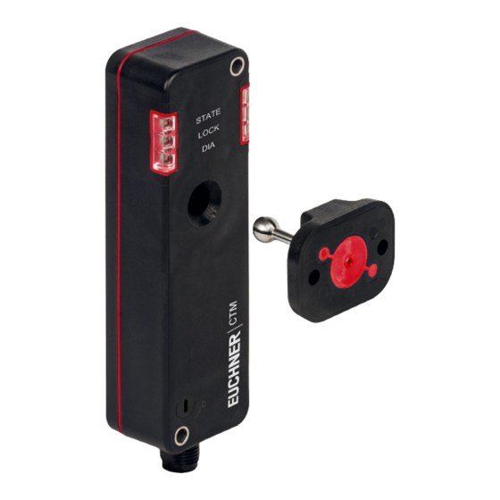
Operating Instructions Transponder-Coded Safety Switch CTM-CBI-BP 6. Function The device permits the locking of movable guards. Safety switch The system consists of the following components: coded actuator (transponder) and switch. Transponder-coded actuator Whether the device learns the complete actuator code (unicode) or not (multicode) depends on the respective version. -
Page 10: Diagnostics Monitoring Output/Bit Oi
Operating Instructions Transponder-Coded Safety Switch CTM-CBI-BP 6.6. Diagnostics monitoring output/bit OI The diagnostic output is switched on in the event of a fault (switch-on condition as for DIA LED). 6.7. Guard lock monitoring output/bit OL The guard lock monitoring output is switched on when guard locking is active. -
Page 11: Switching States
Operating Instructions Transponder-Coded Safety Switch CTM-CBI-BP 6.11. Switching states The detailed switching states for your switch can be found in the system status table. All safety outputs, monitoring outputs and display LEDs are described there. Guard closed and locked Guard closed and not locked... -
Page 12: Manual Release
Operating Instructions Transponder-Coded Safety Switch CTM-CBI-BP 7. Manual release Important! Ì All release functions latch when the device is electrically isolated. Ì Guard locking remains released when the release function is reset. Some situations require the guard locking to be released manually (e.g. malfunctions or an emergency). A function test should be performed after release. -
Page 13: Mounting
Operating Instructions Transponder-Coded Safety Switch CTM-CBI-BP 8. Mounting CAUTION Safety switches must not be bypassed (bridging of contacts), turned away, removed or otherwise rendered ineffective. Ì Observe EN ISO 14119:2013, section 7, for information about reducing the possibilities for by- passing an interlocking device. -
Page 14: Electrical Connection
Operating Instructions Transponder-Coded Safety Switch CTM-CBI-BP 9. Electrical connection The following connection options are available: Ì Connection to a control system Ì Connection to safety relay ESM-CB with integrated BR/IO-Link Gateway Ì Connection to a BR/IO-Link Gateway GWY-CB-1-BR-IO. WARNING In the event of a fault, loss of the safety function due to incorrect connection. -
Page 15: Notes About
Operating Instructions Transponder-Coded Safety Switch CTM-CBI-BP 9.1. Notes about Important! Ì For use and operation as per the requirements , a power supply with the feature for use in Class 2 circuits must be used. Alternative solutions must comply with the following requirements: Electrically isolated power supply unit in combination with fuse as per UL248. -
Page 16: Requirements For Connecting Cables
Ì On the use of other connection components, the requirements in the following table apply. EUCHNER provides no warranty for safe function in case of failure to comply with these require- ments. Observe the following requirements with respect to the connecting cables: For safety switch CTM-…-BP-…-SA-…... -
Page 17: Connector Assignment Of Safety Switch Ctm
Diagnostics monitoring output OD/C Door monitoring output/communication Guard lock monitoring output 1) Only for standard EUCHNER connecting cable. 9.6. Using communication data A device with a gateway function is required in order use the device’s communication data and forward them to a higher-level bus system. -
Page 18: Cyclical Data (Process Data)
Operating Instructions Transponder-Coded Safety Switch CTM-CBI-BP 9.6.4. Cyclical data (process data) Table 2: Cyclical data (process data) Data Meaning Guard position This signal indicates whether the guard is open or closed. Safety outputs switched This signal indicates whether the safety outputs are switched on. The guard must be closed and all other conditions must be met for this purpose. -
Page 19: Acyclical Data (Device Data And Events)
26. A detailed example of connecting and setting the parameters of the control system is available for many devices at www.euchner.com, in the area Service/Downloads/Applications. The features of the respective device are dealt with there in greater detail. -
Page 20: Setup
Operating Instructions Transponder-Coded Safety Switch CTM-CBI-BP 10. Setup 10.1. Device configuration and teach-in operation Guard lock monitoring of the device can be configured using the function actuators. The device must be configured and the actuator must be allocated to the safety switch using a teach-in function before the system forms a functional unit. -
Page 21: Functional Check
Operating Instructions Transponder-Coded Safety Switch CTM-CBI-BP 10.3. Functional check WARNING Danger of fatal injury as a result of faults in installation and functional check. Ì Before carrying out the functional check, make sure that there are no persons in the danger zone. -
Page 22: System Status Tables
Operating Instructions Transponder-Coded Safety Switch CTM-CBI-BP 11. System status tables 11.1. Guard lock monitoring activated LED indicator Output Operating mode State 5 Hz Power Up closed Normal operation, door closed and locked Normal operation, door closed and locked, safety outputs not switched because:... - Page 23 Operating Instructions Transponder-Coded Safety Switch CTM-CBI-BP After the cause has been remedied, faults can generally be reset by opening and closing the guard (when DIA flashes inversely once). Otherwise, briefly disconnect the power supply. Contact the manufacturer if the fault could not be reset after restarting.
-
Page 24: Guard Lock Monitoring Deactivated
Operating Instructions Transponder-Coded Safety Switch CTM-CBI-BP 11.2. Guard lock monitoring deactivated LED indicator Output Operating mode State 5 Hz Power Up closed Normal operation, door closed and locked Normal operation, door closed and locked, safety outputs not switched because: closed inverse - Preceding device in the switch chain is signaling “door... - Page 25 Operating Instructions Transponder-Coded Safety Switch CTM-CBI-BP After the cause has been remedied, faults can generally be reset by opening and closing the guard (when DIA flashes inversely once). Otherwise, briefly disconnect the power supply. Contact the manufacturer if the fault could not be reset after restarting.
-
Page 26: Technical Data
Operating Instructions Transponder-Coded Safety Switch CTM-CBI-BP 12. Technical data NOTICE If a data sheet is included with the product, the information on the data sheet applies. 12.1. Technical data for safety switch CTM-LBI-BR Parameter Value Unit min. typ. max. General... -
Page 27: Typical System Times
Operating Instructions Transponder-Coded Safety Switch CTM-CBI-BP 12.1.1. Typical system times Refer to the technical data for the exact values. Ready delay: After switching on, the device carries out a self-test. The system is ready for operation only after this time. -
Page 28: Radio Frequency Approvals
Operating Instructions Transponder-Coded Safety Switch CTM-CBI-BP 12.2. Radio frequency approvals FCC ID: 2AJ58-07 22052-07 FCC/IC-Requirements This device complies with part 15 of the FCC Rules and with Industry Canada’s licence-exempt RSSs. Operation is subject to the following two conditions: 1) This device may not cause harmful interference, and 2) this device must accept any interference received, including interference that may cause undesired operation. -
Page 29: Dimension Drawing For Safety Switch Ctm
Operating Instructions Transponder-Coded Safety Switch CTM-CBI-BP 12.3. Dimension drawing for safety switch CTM… Necessary minimum travel + permissible overtravel Approach direction Horizontal (h) 21 + 2 ∅ 4.5 (2x) For M4 screw LEDs Auxiliary release (optional) Center offset m = ± 2 mm max. -
Page 30: Technical Data For Actuator S-B-0.-A1
Operating Instructions Transponder-Coded Safety Switch CTM-CBI-BP 12.4. Technical data for actuator S-B-0.-A1… Value Parameter Unit min. typ. max. Material - Housing Ultradur black - Ball holder Stainless steel - Elastomer Resistance Resistant to chemicals and oil Food safe DIN EN 1672-2, DIN EN ISO 14159, PAH category 3 Weight 0.0194... -
Page 31: Ordering Information And Accessories
13. Ordering information and accessories Tip! Suitable accessories, e.g. cables or assembly material, can be found at www.euchner.com. To order, enter the order number of your item in the search box and open the item view. Accessories that can be combined with the item are listed in Accessories. -
Page 32: Declaration Of Conformity
Operating Instructions Transponder-Coded Safety Switch CTM-CBI-BP 16. Declaration of conformity (Translation of the original operating instructions) 2541786-01-10/20... - Page 33 Operating Instructions Transponder-Coded Safety Switch CTM-CBI-BP 2541786-01-10/20 (Translation of the original operating instructions)
- Page 34 Edition: 2541786-01-10/20 Title: Operating Instructions Transponder-Coded Safety Switch CTM-CBI-BP (Translation of the original operating instructions) Copyright: © EUCHNER GmbH + Co. KG, 10/2020 Subject to technical modifications; no responsibility is accept- ed for the accuracy of this information.
Need help?
Do you have a question about the CTM-CBI-BP and is the answer not in the manual?
Questions and answers