
Subscribe to Our Youtube Channel
Related Manuals for EUCHNER CTM-LBI-BP


Summary of Contents for EUCHNER CTM-LBI-BP
- Page 1 Operating Instructions Transponder-Coded Safety Switch with Guard Locking CTM-LBI-BP/BR Unicode/Multicode...
-
Page 2: Table Of Contents
Operating Instructions Transponder-Coded Safety Switch CTM-LBI-BP/BR Contents About this document ..................... 4 1.1. Scope ............................4 1.2. Target group ..........................4 1.3. Key to symbols ..........................4 1.4. Supplementary documents ......................4 Correct use ......................5 Description of the safety function ................6 3.1. - Page 3 Operating Instructions Transponder-Coded Safety Switch CTM-LBI-BP/BR 9.7. Connector assignment of safety switch CTM-…-BP-…-SA-166087/166088 with plug connector M12, 8-pin ......................17 9.8. Connector assignment of safety switch CTM-…-BR-…-SA-… with plug connector M12, 8-pin ......................17 9.9. Connector assignment of safety switch CTM-…-BR-…-AZD-SA-… with plug connector M12, 8-pin ......................17 9.10.
-
Page 4: About This Document
1. About this document 1.1. Scope These operating instructions are valid for all CTM-LBI-BP/BR… from version V1.0.0. These operating instructions, the doc- ument Safety information and any enclosed data sheet form the complete user information for your device. 1.2. Target group Design engineers and installation planners for safety devices on machines, as well as setup and servicing staff possessing special expertise in handling safety components. -
Page 5: Correct Use
Ì EN 60204-1 The safety switch is allowed to be operated only in conjunction with the intended EUCHNER actuator and the related connec- tion components from EUCHNER. On the use of different actuators or other connection components, EUCHNER provides no warranty for safe function. -
Page 6: Description Of The Safety Function
Operating Instructions Transponder-Coded Safety Switch CTM-LBI-BP/BR 3. Description of the safety function Devices from this series feature the following safety functions: Monitoring of guard locking and the position of the guard (interlocking device with guard locking according to EN ISO 14119) Ì... -
Page 7: Control Of Guard Locking For Variants With Imp/Imm Connection
Operating Instructions Transponder-Coded Safety Switch CTM-LBI-BP/BR 3.1. Control of guard locking for variants with IMP/IMM connection If the device is used as guard locking for personnel protection, the control of the guard locking must be regarded as a safety function. -
Page 8: Exclusion Of Liability And Warranty
Operating Instructions Transponder-Coded Safety Switch CTM-LBI-BP/BR 4. Exclusion of liability and warranty In case of failure to comply with the conditions for correct use stated above, or if the safety regulations are not followed, or if any servicing is not performed as required, liability will be excluded and the warranty void. -
Page 9: Function
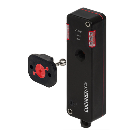
Operating Instructions Transponder-Coded Safety Switch CTM-LBI-BP/BR 6. Function The device permits the locking of movable guards. Safety switch The system consists of the following components: coded actuator (transponder) and switch. Transponder-coded actuator Whether the device learns the complete actuator code (unicode) or not (multicode) depends on the respective version. -
Page 10: Locking Element Signal Ols
Operating Instructions Transponder-Coded Safety Switch CTM-LBI-BP/BR 6.3.5. Locking element signal OLS The locking element signal is present if the locking element is stuck and it is therefore not possible to activate/deactivate guard locking. The signal is reset as soon as the actuator is no longer under tensile stress. -
Page 11: Switching States
Operating Instructions Transponder-Coded Safety Switch CTM-LBI-BP/BR 6.5. Switching states The detailed switching states for your switch can be found in the system status table. All safety outputs, signals and display LEDs are described there. 6.5.1. Switching states with control via the control input IMP... -
Page 12: Manual Release
Operating Instructions Transponder-Coded Safety Switch CTM-LBI-BP/BR 7. Manual release Important! Ì All release functions latch when the device is electrically isolated. Ì Guard locking remains released when the release function is reset. Some situations require the guard locking to be released manually (e.g. malfunctions or an emergency). A function test must be performed after release. -
Page 13: Mounting
Operating Instructions Transponder-Coded Safety Switch CTM-LBI-BP/BR 8. Mounting CAUTION Safety switches must not be bypassed (bridging of contacts), turned away, removed or otherwise rendered ineffective. Ì Observe EN ISO 14119:2013, section 7, for information about reducing the possibilities for by- passing an interlocking device. -
Page 14: Electrical Connection
Operating Instructions Transponder-Coded Safety Switch CTM-LBI-BP/BR 9. Electrical connection The following connection options are available: Ì Separate operation Ì Series connection with Y-distributors or passive distribution modules Ì Series connection, e.g. with wiring in the control cabinet Ì Connection to a BR/IO-Link Gateway GWY-CB-1-BR-IO Ì... -
Page 15: Notes About
Use connection components and connecting cables from EUCHNER. Ì On the use of other connection components, the requirements in the following table apply. EUCHNER provides no warranty for safe function in case of failure to comply with these require- ments. 2525462-03-06/21 (translation of the original operating instructions) -
Page 16: Maximum Cable Lengths With Br Switch Chains
Operating Instructions Transponder-Coded Safety Switch CTM-LBI-BP/BR Observe the following requirements with respect to the connecting cables: For safety switch CTM-…-BP/BR-…-SA-… with plug connector M12, 8-pin Parameter Value Unit Conductor cross-section, min. 0.25 mm² R max. W/km C max. nF/km L max. -
Page 17: Connector Assignment Of Safety Switch Ctm
Electronics and solenoid operating voltage, 0 V DC Solenoid control input, 24 V DC 1) Only for standard EUCHNER connecting cable 2) Monitoring output Ox can assume the function OD (door position) oder OL (guard locking). More detailed information about your device is available at www.euchner.com. -
Page 18: Connector Assignment Of Safety Switch Ctm
Operating Instructions Transponder-Coded Safety Switch CTM-LBI-BP/BR 9.10. Connector assignment of safety switch CTM-…-BR-…-SP-… with plug connector M12, 12-pin Plug connector Designation Function (view of connection side) Electronics and solenoid operating voltage, 24 V DC FI1A Enable input, channel A 0VUB Electronics and solenoid operating voltage, 0 V DC... -
Page 19: Connector Assignment Of Y-Distributor For Series Connection Without Io-Link Communication
Operating Instructions Transponder-Coded Safety Switch CTM-LBI-BP/BR 9.12. Connector assignment of Y-distributor for series connection without IO-Link com- munication Connector assignment of Y-distributor (8-pin, socket) Function X1.1 FI1B Important! X1.2 X1.3 FO1A All guard locking solenoids are always X1.4 FO1B controlled simultaneously on the use of X1.5... -
Page 20: Connector Assignment Of Y-Distributor For Series Connection With Io-Link Communication
Operating Instructions Transponder-Coded Safety Switch CTM-LBI-BP/BR 9.13. Connector assignment of Y-distributor for series connection with IO-Link communi- cation Connector assignment of Y-distributor (8-pin, socket) Function X1.1 FI1B X1.2 X1.3 FO1A X1.4 FO1B X1.5 X1.6 FI1A X1.7 0VUB X1.8 n.c. Y-distributor... -
Page 21: Connection Of A Single Ctm-Bp/Br (Separate Operation)
The user is responsible for safe integration into the overall system. Detailed application examples can be found at www.euchner.com. Simply enter the order number of your switch in the search box. You will find all available connection examples for the device in Downloads. - Page 22 Operating Instructions Transponder-Coded Safety Switch CTM-LBI-BP/BR 24V DC 24V DC Actuator Monitoring Outputs Read Head Door Monitoring Diagnostic Safety Outputs OD/C FO1A FO1B Connected load BR evaluation via PLC Fig. 2: Connection example with control input IMM (translation of the original operating instructions) 2525462-03-06/21...
-
Page 23: Connection Of Several Devices In A Switch Chain (Series Connection)
The user is responsible for safe inte- gration into the overall system. Detailed application examples can be found at www.euchner.com. Simply enter the order number of your switch in the search box. You will find all available connec- tion examples for the device in Downloads. - Page 24 Operating Instructions Transponder-Coded Safety Switch CTM-LBI-BP/BR Fig. 3: Connection example for series connection with control of guard locking via IO-Link communication (translation of the original operating instructions) 2525462-03-06/21...
- Page 25 Operating Instructions Transponder-Coded Safety Switch CTM-LBI-BP/BR Fig. 4: Connection example for series connection with control of guard locking via the control input IMP 2525462-03-06/21 (translation of the original operating instructions)
-
Page 26: Using Communication Data
Operating Instructions Transponder-Coded Safety Switch CTM-LBI-BP/BR 10. Using communication data A BR/IO-Link Gateway is required to use the device’s communication data and forward them to a higher-level bus system. The following devices are suitable: Ì GWY-CB-1-BR-IO (BR/IO-Link Gateway) Ì ESM-CB (safety relay with integrated BR/IO-Link Gateway) 10.1. -
Page 27: Acyclical Data (Device Data And Events)
Operating Instructions Transponder-Coded Safety Switch CTM-LBI-BP/BR 10.3.2. Acyclical data (device data and events) Table 4: Acyclical data (examples) Command Answer Use in device Meaning Category (number of bytes) classes General information Send device ID-number/ PWR-UP serial number Send device Versions... -
Page 28: Notes On Operation With Safe Control Systems
With series connection: Always connect inputs FI1A and FI1B directly to a power supply unit or to outputs FO1A and FO1B of another EUCHNER BR device. Pulsed signals must not be present at inputs FI1A and FI1B. A detailed example of connecting and setting the parameters of the control system is available for many devices at www.euchner.com, in the area Service/Downloads/Applications/CTM. -
Page 29: Setup
Operating Instructions Transponder-Coded Safety Switch CTM-LBI-BP/BR 11. Setup 11.1. LED displays You will find a detailed description of the signal functions in chapter 12. System status table on page 31. Color STATE green LOCK yellow STATE LOCK 11.2. Teach-in function for actuator (only for unicode evaluation) The actuator must be allocated to the safety switch using a teach-in function before the system forms a functional unit. -
Page 30: Functional Check
Operating Instructions Transponder-Coded Safety Switch CTM-LBI-BP/BR 11.3. Functional check WARNING Danger of fatal injury as a result of faults in installation and functional check. Ì Before carrying out the functional check, make sure that there are no persons in the danger zone. -
Page 31: System Status Table
Operating Instructions Transponder-Coded Safety Switch CTM-LBI-BP/BR 12. System status table LED indicator Output Operating mode State 5 Hz Power Up closed Normal operation, door closed and locked 1 x in- Normal operation closed Normal operation, door closed and not locked verse... - Page 32 Operating Instructions Transponder-Coded Safety Switch CTM-LBI-BP/BR When DIA flashes inversely once, the fault display can generally be reset by opening and closing the guard after remedying the cause. If the fault is still displayed afterward, as well as for all other fault displays, briefly interrupt the power supply.
-
Page 33: Technical Data
Operating Instructions Transponder-Coded Safety Switch CTM-LBI-BP/BR 13. Technical data NOTICE If a data sheet is included with the product, the information on the data sheet applies. 13.1. Technical data for safety switch CTM-LBI Parameter Value Unit min. typ. max. General... -
Page 34: Typical System Times
Operating Instructions Transponder-Coded Safety Switch CTM-LBI-BP/BR 13.1.1. Typical system times Refer to the technical data for the exact values. Ready delay: After switch-on, the device carries out a self-test. The system is ready for operation only after this time. Turn-on time of safety outputs: The max. reaction time t is the time from the moment when the guard is locked to the moment when the safety outputs switch on. -
Page 35: Radio Frequency Approvals
Operating Instructions Transponder-Coded Safety Switch CTM-LBI-BP/BR 13.2. Radio frequency approvals FCC ID: 2AJ58-07 22052-07 FCC/IC-Requirements This device complies with part 15 of the FCC Rules and with Industry Canada’s licence-exempt RSSs. Operation is subject to the following two conditions: 1) This device may not cause harmful interference, and 2) this device must accept any interference received, including interference that may cause undesired operation. -
Page 36: Dimension Drawing For Safety Switch Ctm
Operating Instructions Transponder-Coded Safety Switch CTM-LBI-BP/BR 13.3. Dimension drawing for safety switch CTM… Necessary minimum travel + perm. overtravel Approach direction Horizontal (h) 21 + 2 ∅ 4.5 (2x) For M4 screw LEDs Auxiliary release (optional) Center offset m = ± 2 mm max. -
Page 37: Technical Data For Actuator A-B-A1-A1
Operating Instructions Transponder-Coded Safety Switch CTM-LBI-BP/BR 13.4. Technical data for actuator A-B-A1-A1-… Value Parameter Unit min. typ. max. Material - Housing Ultradur black - Ball holder Stainless steel - Elastomer A-B-A1-161642: FKM red / A-B-A1-161643: FKM blue Resistance Resistant to chemicals and oil Food safe DIN EN 1672-2, DIN EN ISO 14159, PAH category 3... -
Page 38: Ordering Information And Accessories
14. Ordering information and accessories Tip! Suitable accessories, e.g. cables or assembly material, can be found at www.euchner.com. To order, enter the order number of your item in the search box and open the item view. Accessories that can be combined with the item are listed in Accessories. -
Page 39: Declaration Of Conformity
La presente declaración de conformidad se expide bajo la exclusiva responsabilidad del fabricante: 15.10.2020 - TL - AL - Blatt/Sheet/ Page/Pagina/ Página 1 EUCHNER GmbH + Co. KG Kohlhammerstraße 16 70771 Leinfelden-Echterdingen Tel. +49/711/7597-0 Fax +49/711/753316 www.euchner.de info@euchner.de 2525462-03-06/21 (translation of the original operating instructions) - Page 40 Responsabilità della documentazione Germany Director de desarrollo electrónico Agente documenta 15.10.2020 - TL - AL - Blatt/Sheet/ Page/Pagina/ Página 2 EUCHNER GmbH + Co. KG Kohlhammerstraße 16 70771 Leinfelden-Echterdingen Tel. +49/711/7597-0 Fax +49/711/753316 www.euchner.de info@euchner.de (translation of the original operating instructions) 2525462-03-06/21...
- Page 41 Operating Instructions Transponder-Coded Safety Switch CTM-LBI-BP/BR 2525462-03-06/21 (translation of the original operating instructions)
- Page 42 Edition: 2525462-03-06/21 Title: Operating Instructions Transponder-Coded Safety Switch CTM-LBI-BP/BR (translation of the original operating instructions) Copyright: © EUCHNER GmbH + Co. KG, 06/2021 Subject to technical modifications; no responsibility is accept- ed for the accuracy of this information.
Need help?
Do you have a question about the CTM-LBI-BP and is the answer not in the manual?
Questions and answers