
Related Manuals for Wilo Sinum MP 10-1-50


Summarization of Contents
General Information
About These Instructions
Instructions are essential for correct handling and use. Read carefully, keep accessible, and observe specifications and markings.
Copyright and Liability
Reproduction is prohibited. Wilo is not liable for inaccuracies or omissions and excludes warranty in specific cases.
Safety Information
Identification of Safety Instructions
Safety instructions are displayed with symbols for danger to persons (grey) and signal words for damage to property (no symbol).
Personnel Qualifications
Personnel must be instructed on accident prevention regulations and understand installation/operating instructions.
Electrical Work Safety
Observe local regulations and energy supply company requirements for electrical connections.
Delivered Components
Check delivered components against the bill of materials for conformity and suitability for intended use.
Transport Safety
Comply with work safety laws. Use approved lifting gear and wear appropriate protective equipment.
Operating Space Requirements
The operating space must meet European regulations and standards, containing necessary equipment for thermal energy and water systems.
Temperature and Pressure Limits
Do not exceed permitted operating temperatures and pressures to prevent damage, malfunctions, and injuries.
Fuses and Safety Devices
Equipment is fitted with safety devices. Decommissioning is required before testing or restoring factory settings.
Examinations and Inspections
Measures ensure operational reliability and compliance. Examinations must be organised by the owner/operator and records kept.
Maintenance and Repair Procedures
Perform maintenance and repair work only with the system shut down. Secure against unintentional restart.
Other Hazards
Be aware of risks from overloaded components, changed ambient conditions, and deactivated safety devices.
Product Description
Functional Principle
Describes the operational cycle of the automat, including cold, warming up, full power, and cooling down phases.
Connection Options
Details connection options like Ethernet, USB, and CAN for BMS, data saving, and multi-product connectivity.
Product Labelling
Presents the labels for the vessel and pump module, including technical specifications and warnings.
Pump Control Type Key
Explains the coding system for pump types, including frequency, manufacturer, power class, and module version.
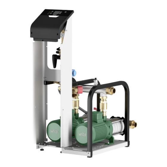
Components and Equipment
Illustrates and lists the main components and equipment of the vessel and system.
Pump Module Components
Details the various components and parts within the pump modules.
Control Unit Overview
Details the components and functions of the control unit, including its interface and connections.
Control Unit Connections Detail
Details the specific item descriptions and their assignments for control unit connections, including power, communication, and fuses.
Application and Use
Intended Use
The product is for closed water-based heating and cooling systems to absorb volume changes and regulate pressure.
Improper Use
Do not use for fluids attacking materials, abrasive fluids, or with incorrect voltage/frequency. Avoid unsuitable system designs.
Transport and Storage
Delivery Process
Product delivered on a pallet. Check packaging for damage upon delivery and report any issues to the supplier.
Safe Transport
Protect from humidity and dirt. Do not remove outer packaging until at the installation site. Demarcate and cordon off the working area.
Storage Conditions
Place on a firm surface. Maintain ambient conditions: 10-40°C, max 50% humidity. Protect from direct sunlight.
Installation and Electrical Connection
Installation Guidelines
Attach automatic aeration. Open screw cap. Install feet and sensors. Align vessel vertically using spirit levels.
Sound Insulation
If necessary, mount sound insulation at contact areas of the module frame and pipework.
Vessel Connection
Connect pump module and vessel using the supplied flexible discharge hose. Observe connection stickers and use flat seals.
Top-up Connection
Mount top-up connection on control unit. Requires supply pressure of 4-6 bar. Install non-return valve with filter if connected to mains.
Draining Connection
Mount drainage equipment near the system for safe drainage of volume flows from safety valves and connections.
System Connection
Mount system connection on the heating or cooling system.
Electrical Connection
Connect power cables according to voltage and phase requirements. Ensure proper earthing and use suitable wiring.
Commissioning
Initial Commissioning Steps
Ensure system suitability and secure installation. Test control unit and pump feed covers. Document commissioning procedure and settings.
Commissioning Menu Items
Symbol, Name, and Function for various menu items like Language selection, Time and date setting, Vessel type selection.
Interface Symbols and Functions
Explains the meaning of symbols used in the interface, their function, and position within the menu structure.
Operating Screen Details
Details the elements displayed on the operating screen, including icons, system pressure, and vessel fill level.
Pressure Settings Configuration
Details the parameters for high pressure alarm, operating pressure upper/lower limits, and low pressure alarm.
Degassing Settings Configuration
Explains the different degassing modes (Normal, Turbo, OFF) and resting profile settings.
Topping Up and Water Treatment
Describes the topping-up process and parameters, including limits and water treatment module functions.
Restart Procedures
Provides instructions and warnings for restarting the system after decommissioning or power outage.
Maintenance
Emptying and Topping Up Vessel
Provides step-by-step instructions for draining and refilling the vessel, including safety precautions.
Additional Maintenance Tasks
Details additional maintenance tasks and inspection schedules, such as electrical equipment checks.
Faults, Causes, and Remedies
Error Message Reference
Lists and explains common error messages, their GUI representation, and the corresponding measures to resolve them.
Fault Diagnosis
Detailed troubleshooting steps and potential causes for various error codes and system anomalies.
Fault Diagnosis
Detailed troubleshooting steps and potential causes for various error codes and system anomalies.
Product Disposal
Electrical Product Collection
Provides guidance on proper disposal and recycling of the product to prevent environmental damage and health hazards.
Annex 1: Technical Data
Installation Data and Distances
Details ambient conditions for bearing and operating space, and minimum distances for installation.
Vessel Dimensions and Weights
Provides technical data on vessel volume, dimensions, and weights for various capacities.
Vessel Operational Characteristics
Details vessel operational characteristics, including pressure, temperature limits, and dimensions.
Pump Module Data
Lists dimensions, weights, and operational characteristics for various pump modules.
Valve and Flow Rate Curves
Presents curves for manual control valves and topping-up flow rate, showing pressure vs. settings and flow.
Annex 3: Electronics Data
Pump Unit Nominal Values
Lists nominal values for pump units, including voltage, current, power, fuses, and protection class.
Control Unit Connection Diagrams
Illustrates connection diagrams for the control unit, showing wiring for pumps, sensors, and communication interfaces.
Need help?
Do you have a question about the Sinum MP 10-1-50 and is the answer not in the manual?
Questions and answers