
Subscribe to Our Youtube Channel
Related Manuals for Wilo Sinum MP M-2-50


Summary of Contents for Wilo Sinum MP M-2-50
- Page 1 Pioneering for You Wilo-Sinum en Installation and operating instructions · 4255992 • Ed.01/2023-09...
-
Page 3: Table Of Contents
Commissioning, volume and operating temperature.. 26 Overview of menu items............ 27 Symbols, function and position ........ 28 Topping up, operation with water treatment module... 31 Restart .................. 31 8 Decommissioning and dismantling ........ 31 9 Maintenance................ 31 Installation and operating instructions • Wilo-Sinum • Ed.01/2023-09... -
Page 4: General Information
All rights reserved. Subject to change Wilo shall reserve the right to change the listed data without notice and shall not be liable for technical inaccuracies and/or omissions. The illustrations used may differ from the ori- ginal and are intended as an exemplary representation of the product. -
Page 5: Personnel Qualifications
Operation/control: Operating personnel, instructed in the func- tioning of the complete system Electrical work • Observe applicable local regulations when connecting to the mains power supply. • Comply with the requirements of the local energy supply com- pany. Installation and operating instructions • Wilo-Sinum • Ed.01/2023-09... -
Page 6: Delivered Components
IT systems. Installation and operating instructions • Wilo-Sinum • Ed.01/2023-09... -
Page 7: Never Exceed The Permitted Temperature And Pressure Values
• Excess pressure and exceeding permitted temperatures can lead to damage to components, malfunctions and serious per- sonal injuries and property damage. • Check equipment and temperature at regular intervals. Installation and operating instructions • Wilo-Sinum • Ed.01/2023-09... -
Page 8: Fuses
Installation and operating instructions • Wilo-Sinum • Ed.01/2023-09... -
Page 9: 2.10 Maintenance And Repair
Overloaded components due to unforeseeable extreme values • Danger to continued operation in the event of changed, unac- ceptable ambient conditions • Danger to continued operation in the event of safety devices being switched off or malfunctioning Installation and operating instructions • Wilo-Sinum • Ed.01/2023-09... -
Page 10: Product Description
For saving the offline logs and configuration para- (also known as USB-A) meters. Second option for the connection: For up- dating the switchgear firmware (download control software). Connection pair for connectivity of multiple products of the series (Master-Slave). Installation and operating instructions • Wilo-Sinum • Ed.01/2023-09... -
Page 11: Connection Options
Nennfrequenz der Betriebsspannung (Hz): 50 = 50 Hz; 60 = 60 Hz; Pumpenhersteller: 1; 2; 3; 4; 5 Leistungsklasse: M; 2; 10; 20; 60; 80; 90; 100; 130 Modul Ausführung: M= Monopumpe; D= Duopumpe Installation and operating instructions • Wilo-Sinum • Ed.01/2023-09... -
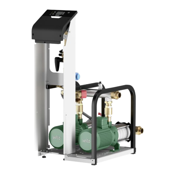
Page 12: Components, Equipment
Valve discharge pipe, system discharge (labelled) Particle filter Non-return valve 3.10 Manual control valve 1 (graph) 3.11 Manual control valve 2 (graph) 3.12 Solenoid valve, overflow valve no. 1 3.13 Solenoid valve, overflow valve no. 2 Installation and operating instructions • Wilo-Sinum • Ed.01/2023-09... - Page 13 3.18 Automatic air vent with anti-suction device 3.19 Control unit, Flextronic 3.20 Drainage pump 3.21 Manual control valve 3 (graph) 3.22 Front panel 3.23 Control unit, Flextronic 400 V WILO G4 M02 WILO G4 D02 Installation and operating instructions • Wilo-Sinum • Ed.01/2023-09...
- Page 14 WILO G4 M10 WILO G4 D10 WILO G4 M20 WILO G4 D20 Installation and operating instructions • Wilo-Sinum • Ed.01/2023-09...
- Page 15 WILO G4 M60 WILO G4 D60 WILO G4 M80 WILO G4 D80 Installation and operating instructions • Wilo-Sinum • Ed.01/2023-09...
- Page 16 WILO G4 M100 WILO G4 D100 WILO G4 M130 WILO G4 D130 Installation and operating instructions • Wilo-Sinum • Ed.01/2023-09...
-
Page 17: Control Unit
Modbus/Bacnet/HFC via RS485 1 B+ 2 B- 3 GND Fuse 1 (P31&P32) 5x20 5A Fuse 2 (P33&P35) 5x20 10AT Fuse 2 (P34&P36) 5x20 10AT Power supply 1 L 2 N 3 PE Cable entry for power supply Installation and operating instructions • Wilo-Sinum • Ed.01/2023-09... - Page 18 230 V output (top-up valve V3) 1 PE 2 L 3 N 230 V output (drain valve (external)) 1 PE 2 L Voltage output, differential pressure valve V1 1 PE 2 L Voltage output, differential pressure valve V2 1 PE 2 L Installation and operating instructions • Wilo-Sinum • Ed.01/2023-09...
-
Page 19: Application/Use
• If lifting accessories are used, wear a safety helmet. WARNING Risk of injury from falling parts! Never allow anyone to stand under suspended loads! • Do not move the load over workplaces where persons are present. Installation and operating instructions • Wilo-Sinum • Ed.01/2023-09... -
Page 20: Delivery
Storage • Ambient conditions: 10 °C to 40 °C, max. humidity: 50 %. • Dry hydraulics and pipework before packing. • Protect the system from humidity and dirt. • Protect the system from direct exposure to sunlight. Installation and operating instructions • Wilo-Sinum • Ed.01/2023-09... -
Page 21: Installation And Electrical Connection
Do not affix vessel to the floor or on the installation surface (do not use a fixation method that could damage the vessel, for example, do not embed the feet in concrete Installation and operating instructions • Wilo-Sinum • Ed.01/2023-09... -
Page 22: Sound Insulation
The vessel connection to the pump module can be either an electrical or hydraulic connec- tion. See Installation diagram and example [” 35] in Annex 1. • Before filling and commissioning the vessel, observe the following: Installation and operating instructions • Wilo-Sinum • Ed.01/2023-09... -
Page 23: Top-Up Connection
(Item 1.3). • Install a drainage funnel and, if necessary, drain pipe for the non-return valve. • Mount system connection on the heating or cooling system. System connection Installation and operating instructions • Wilo-Sinum • Ed.01/2023-09... -
Page 24: Electrical Connection
• Mount non-return valve in the immediate vicinity of the system connection on the con- trol unit. The non-return valve must be protected against being switched off by acci- dent. Electrical connection Installation and operating instructions • Wilo-Sinum • Ed.01/2023-09... -
Page 25: Commissioning
(e.g. power supply available and connected, functioning and active fuse protec- tion, system leakproof, volume sensor transport protection removed). CAUTION Damage to property may occur due to incorrect commission- ing! Only fill the vessel after all commissioning measures. Installation and operating instructions • Wilo-Sinum • Ed.01/2023-09... -
Page 26: Commissioning, Volume And Operating Temperature
[” 27]). The commissioning procedure includes selecting the language. • Scan the label of the Wilo-Sinum main vessel or select it based on its rated capacity (La- belling [” 11], rating plate of the vessel). • Perform the factory-set operational calibration (Overview of menu items [” 27]). -
Page 27: Overview Of Menu Items
Vessel type selection – vessel Select the (main) vessel calibration Setting the pressure Set the desired pressure default value Accessories selection Select the additional control functions of the automat Commissioning overview Confirm the automat settings Installation and operating instructions • Wilo-Sinum • Ed.01/2023-09... -
Page 28: Symbols, Function And Position
General Open the general settings menu Alarms Assign alarm signals to the potential-free outputs Accessories Activate the extended con- trol accessories Time/date Set the time and date Installation and operating instructions • Wilo-Sinum • Ed.01/2023-09... - Page 29 Operating Display the performance hours statistics USB detected Save the log file to a USB stick * Only available after login Operating data Menu Settings Display Installation and operating instructions • Wilo-Sinum • Ed.01/2023-09...
- Page 30 6 Degassing is allowed daily between 10 a.m. and 5 p.m. 7 Degassing is allowed daily between 9 a.m. and 9 p.m. 8 Degassing is allowed on weekdays and Saturdays between 7 p.m. and 7 a.m. and Sundays Installation and operating instructions • Wilo-Sinum • Ed.01/2023-09...
-
Page 31: Topping Up, Operation With Water Treatment Module
Decide on the purpose or reuse of system water in accordance with applicable regula- tions. • System water may be treated (antifreeze or other additives). Discuss the provisions for reuse of components with the waste disposal contractor. Installation and operating instructions • Wilo-Sinum • Ed.01/2023-09... -
Page 32: Maintenance
Perform regular inspections of the electronics. See “Components, pump modules [” 12]”. Emptying and topping up the ves- If the expansion water from the main or auxiliary vessel has to be drained, proceed as fol- lows: Installation and operating instructions • Wilo-Sinum • Ed.01/2023-09... -
Page 33: Additional Maintenance Work
Pump failure. Check pump functionality. If no solution can be found, contact customer service. Maximum running time error – load-sensitive Pump failure. Check pump functionality. If no solution can be found, pumps contact customer service. Installation and operating instructions • Wilo-Sinum • Ed.01/2023-09... - Page 34 Membrane is broken. Replace membrane. Increased water level in vessel without Wilo-Sinum Potential error of the manifold, top-up or non-return valve activity Reduction of water level in vessel without Wilo- Potential leak in the vessel or connection assemblies or drain valve Sinum activity fault...
-
Page 35: Spare Parts
Observe the locally applicable regulations! Please consult your local municipality, the nearest waste disposal site, or the dealer who sold the product to you for information on proper disposal. See www.wilo‑recycling.com for more information about recycling. Subject to change without prior notice! Annex 1 13.1... - Page 36 Not necessary according to DIN EN 12828 • Add additional auxiliary vessels symmetrically with a manifold (main vessel in the middle) with due regards to minimum distances. The branch line from the main vessel must be flexible. Installation and operating instructions • Wilo-Sinum • Ed.01/2023-09...
-
Page 37: Technical Data, Specifications, Hydraulics Systems
** Accessories, optional extras Annex 2 14.1 Technical data, specifications, hy- draulics systems 14.1.1 Vessel: Volume, dimensions and weights Installation and operating instructions • Wilo-Sinum • Ed.01/2023-09... - Page 38 14.1.2 Vessel: Operational characteristics Installation and operating instructions • Wilo-Sinum • Ed.01/2023-09...
- Page 39 14.1.3 Pump module: Dimensions and weights 14.1.4 Pump module: Operational charac- teristics Installation and operating instructions • Wilo-Sinum • Ed.01/2023-09...
- Page 40 14.1.5 Manual control valve: Default val- 14.1.6 Topping up, flow rate Installation and operating instructions • Wilo-Sinum • Ed.01/2023-09...
-
Page 41: Technical Data, Information, Electronics
Annex 3 15.1 Technical data, information, elec- tronics 15.1.1 Pump unit: Nominal values Installation and operating instructions • Wilo-Sinum • Ed.01/2023-09... - Page 42 15.1.2 Control unit: Connection diagrams Installation and operating instructions • Wilo-Sinum • Ed.01/2023-09...
- Page 44 Local contact at www.wilo.com/contact WILO SE Wilopark 1 44263 Dortmund Germany T +49 (0)231 4102-0 T +49 (0)231 4102-7363 wilo@wilo.com Pioneering for You www.wilo.com...
Need help?
Do you have a question about the Sinum MP M-2-50 and is the answer not in the manual?
Questions and answers