Table of Contents
Advertisement
Quick Links
Water Closet Battery Models:
ZER6000AV-ONE-HYD
ZER6000AV-HET-HYD
ZER6000AV-WS1-HYD
ZER6000AV-DF-HYD
ZER6000AV-DF-HET
Compliance:
• ADA Compliant
• ASSE 1037/ASME A112.1037/CSA B125.37
• cUPC
WARNING: Cancer and Reproductive Harm - www.P65Warnings.ca.gov
ADVERTENCIA: Cáncer y daño reproductivo - www.P65Warnings.ca.gov
AVERTISSEMENT: Cancer et effets néfastes sur la reproduction - www.P65Warnings.ca.gov
All goods sold hereunder are warranted to be free from defects in material and factory workmanship for a period of three years from the date of purchase.
Decorative finishes warranted for one year. We will replace at no costs goods that prove defective provided we are notified in writing of such defect and the
goods are returned to us prepaid at Sanford, NC, with evidence that they have been properly maintained and used in accordance with instructions. We shall
not be responsible for any labor charges or any loss, injury or damages whatsoever, including incidental or consequential damages. The sole and exclusive
remedy shall be limited to the replacement of the defective goods. Before installation and use, the purchaser shall determine the suitability of the product for his
intended use and the purchaser assumes all risk and liability whatever in connection therewith. Where permitted by law, the implied warranty of merchantability
is expressly excluded. If the products sold hereunder are "consumer products," the implied warranty of merchantability is limited to a period of three years and
shall be limited solely to the replacement of the defective goods. All weights stated in our catalogs and lists are approximate and are not guaranteed.
NOTICE: READ ENTIRE MANUAL PRIOR TO INSTALLING PRODUCT
AVIS : LIRE L'ENSEMBLE DU MANUEL AVANT D'INSTALLER LE PRODUIT
1.1 gpf
1.28 gpf
1.6 gpf
1.1/1.6 gpf
1.1/1.28 gpf
LIMITED WARRANTY
AquaSense
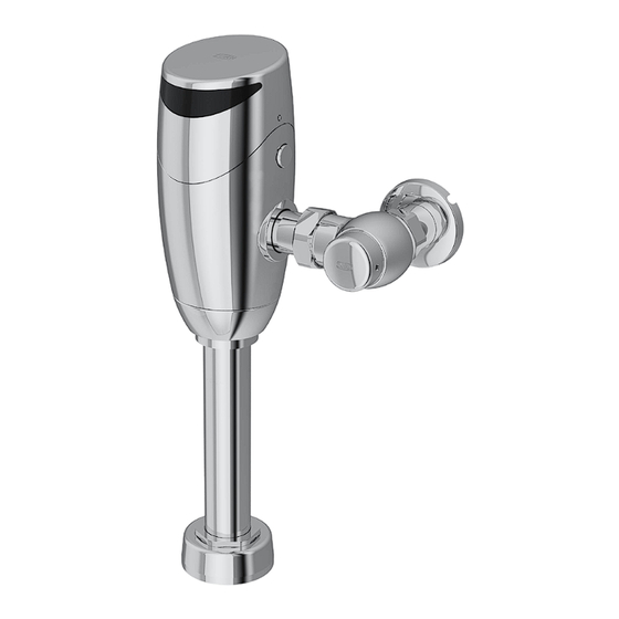
ZER-HYD Series
Automatic Sensor-Operated Gear
Driven Type Flush Valves for Water
Closets and Urinals
Installation, Operation, Maintenance
and Parts Manual
Urinal Battery Models:
ZER6003AV-ULF-HYD
ZER6003AV-EWS-HYD
ZER6003AV-WS1-HYD
• Texas Accessibility Standard (TAS)
• WaterSense Compliant
®
0.125 gpf
0.5 gpf
1.0 gpf
Advertisement
Table of Contents

Related Manuals for ZURN AquaSense ZER6000AV-HYD


Summary of Contents for ZURN AquaSense ZER6000AV-HYD
- Page 1 AquaSense ® ZER-HYD Series Automatic Sensor-Operated Gear Driven Type Flush Valves for Water Closets and Urinals Installation, Operation, Maintenance and Parts Manual Water Closet Battery Models: Urinal Battery Models: ZER6000AV-ONE-HYD 1.1 gpf ZER6003AV-ULF-HYD 0.125 gpf ZER6000AV-HET-HYD 1.28 gpf ZER6003AV-EWS-HYD 0.5 gpf ZER6000AV-WS1-HYD 1.6 gpf ZER6003AV-WS1-HYD...
-
Page 2: Specifications
Operating Temperature: 35°F to 104°F [2°C to 40°C] Important Safety Information • Do not convert or modify this Zurn product. All warranties will be voided. • All plumbing is to be installed in accordance with applicable codes and regulations. • Water supply lines must be sized to provide an adequate volume of water for each fixture. -
Page 3: Required Tools
Required Tools Optional Accessories Strap Wrench 3/32”, 5/64” Phillips Head Hex Key Screwdriver (Supplied) Flat Head Smooth Jawed Magic Magnet Screwdriver Wrench P6900-AT-MAG Sweat Solder Adapter Installation Instructions NOTE: Before installation, turn off water supplies to existing fixture and remove flushometer if replacing an existing device. 1. Measure distance from finished wall to the center line of the 2. - Page 4 Control Stop Installation Instructions 1. Install control stop assembly by threading it onto water supply 2. When all stop valves are properly connected to the water supply pipe and tightening with a smooth jawed wrench. Apply thread line and water pressure is available open the control stop using a sealing compound or pipe tape to the male NPT thread on sweat flathead screwdriver and turning the stop valve adjustment screw solder adapter only.
-
Page 5: Battery Installation
Battery Installation 2. As shown, insert 2 AA Alkaline batteries (supplied) into the battery 1. Turn both set screw through the small holes on the side of the tray as backup batteries. valve head counterclockwise with the 3/32” Allen Wrench until they are back into the valve head. Then, remove the valve head by lifting it up. Wire Harness Connection - Right Side Water Supply 1. - Page 6 Wire Harness Connection - Left Side Water Supply 1. Connect the connector from the valve head to the connector from 2. Rotate the valve head to have the sensor lens facing the front. the valve body carefully. 3. Bundle the wire harness neatly and flat across the rechargeable 4. Follow right hand installation instruction to install flush valve with battery and position the connectors in the vacant area shown. the sensor lens facing the back wall up to Harness Connection Next, slowly lower valve head back onto valve body. Reinstall the step.
- Page 7 Diaphragm Replacement and Cleaning 1. Turn off control stop using a flat head screwdriver turning 2. Loosen the set screws through two small holes on the shroud clockwise. Afterward, utilize the manual override button to flush escutcheon by turning counter-clockwise. Uninstall shroud water out of the flush valve. escutcheon from the valve body by turning it counter-clockwise and lower it from the shroud.
- Page 8 Diaphragm Replacement and Cleaning (Cont.) 5. Remove the existing diaphragm kit from the manifold stem. Thoroughly wash the diaphragm and orifice using water. Install the cleaned diaphragm back into the valve body, ensure that Volume the orifice is facing the correct orientation. For the correct orifice Control Ring orientation, Refer to the retrofit installation instruction section. Manifold Stem If the issue persists after cleaning, proceed to step 5B. Do not to damage or enlarge orifice. Doing so will result in incorrect flush rate. 5B. Remove the existing diaphragm kit from the manifold stem. If the o-rings show signs of wear or damage, replace them with the new ones provided in the diaphragm repair kit. Install a new diaphragm kit (with matching flow rate) into the valve body, ensure that the both orifices are positioned inline with the control stop.
-
Page 9: Care And Cleaning Instruction
Valves used in installations subject to shut down because of cold and freezing conditions should be maintained in the following manner. After the main supply has been shut off and the water drained from the system, remove the stop valve cap and stop valve internals to allow the water to drain from the flush valve itself. Dual Flush User Guide (For ZER6000AV-DF Only) • The Dual Flush model supplies flush volumes of 1.1 and 1.6 gallons per flush. When a user is present for less than 60 seconds, the valve will flush with 1.1 gallons of water. When a user is present for over 60 seconds, the valve consumes 1.6 gallons of water. A user must be present for a minimum of 8 seconds in order to trigger a flush. • The Dual Flush model must be paired with a fixture with a flush volume range that includes 1.1 to 1.6 gallons per flush. For a list of recommended bowls, please refer to our website, www.zurn.com, or speak with your local Zurn rep. FV845 Rev. A 5/1/2024 Page 8... -
Page 10: Troubleshooting Guide
Trouble Shooting Guide Problem Indicator Cause Corrective Action No water flushed. Stop valve is closed Open stop valve Sensor flashes 5 times in Flush cycle did not complete Contact Customer Service for further quick succession instruction Batteries not making contact No sensor light Remove and reinstall batteries correctly, Critically low battery voltage or replace batteries See Battery installation for reference. - Page 11 Trouble Shooting Guide Problem Indicator Cause Corrective Action By-pass orifice is plugged or partially Examine by-pass orifice and clean if plugged. necessary being certain not to en- Valve is flushing too long or High water delivery or large orifice opening. (See Diaphragm not shutting off. continuous flow. Replacement and Cleaning Section for cleaning instruction) Supply volume is too high. Slowly close the control stop to lower water pressure.
- Page 12 Rev. A | Date: 5/1/2024 | C.N. No. 145585 | Prod./Dwg. No. FV845 Patent zurn.com/patents US 1.855.ONE.ZURN CANADA 1.877.892.5216 ZURN.COM...
Need help?
Do you have a question about the AquaSense ZER6000AV-HYD and is the answer not in the manual?
Questions and answers