Advertisement
Quick Links
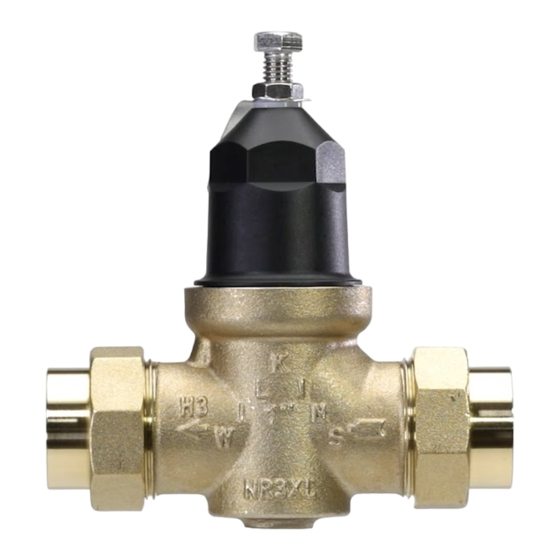
Model NR3XL
LEAD-FREE Pressure Reducing Valve with Integral By-pass
(1/2", 3/4", 1", 1-1/4" 1-1/2" & 2")
Installation Inspection Maintenance Repair Instructions
Annual inspection and maintenance is required of all plumbing system components. To ensure proper performance and maximum
life, this product must be subject to regular visual inspection and pressure testing, with cleaning or repair as needed. If the end user
is not qualified to perform periodic inspection and maintenance, a qualified licensed plumber must be contacted for assistance. It
is also recommended that a suitable strainer be installed upstream of the valve. Anytime a pressure reducing valve is adjusted, a
pressure gauge must be used downstream to verify correct pressure setting. Do not bottom out adjustment bolt on bell housing.
Where the desired pressure reduction is more than a 3 to 1 ratio (i.e. 225psi to 75psi), or inlet pressure is above 150 PSI multiple
regulators in series are recommended to be installed to prolong valve life.
Installation Instructions
1. This valve should be installed by a qualified licensed plumber.
2. Flush supply line to remove loose dirt and scale which may damage the seal ring and seat.
3. Install valve in-line with arrow on valve body pointing in the direction of flow. The valve shall be installed in an accessible loca-
tion and may be installed in any orientation.
4. All valves are factory set to approximately 50 PSI, adjust regulator to desired outlet set pressure by turning adjustment bolt
clockwise (into bell housing) to raise pressure or counterclockwise (out of bell housing) to reduce pressure.
NOTE: When reducing pressure open a downstream faucet to relieve pressure and use a pressure gauge
(Zurn Wilkins Model HGI-25) to verify correct pressure setting.
5. Tighten locknut when desired pressure is achieved and test valve to confirm proper operation.
Inspection and Maintenance Instructions
Tools Required:
•
Hose Bibb Pressure gauge (Zurn Wilkins Model HGI-25)
•
9/16" wrench for bolt adjustment
•
Pliers for cartridge removal
•
Crescent wrench for bell removal
•
Silicone based food grade o-ring grease
Testing:
1.
If available, determine the incoming supply pressure for reference.
2.
Install the pressure gauge
3.
Open a downstream fixture inside the dwelling to start flow through the valve.
4.
Record the reading on the pressure gauge for reference. This is the reduced flowing pressure.
5.
Close the inside faucet or fixture and immediately record the reading on the pressure gauge. This is the reduced static
pressure and outlet set point of the valve.
6.
Observe the gauge for 10 minutes.
WARRANTY: ZURN WILKINS Valves are guaranteed against defects of material or workmanship when used for the services recom-
mended. If in any recommended service, a defect develops due to material or workmanship, and the device is returned, freight prepaid,
to ZURN WILKINS within 12 months from date of purchase, it will be repaired or replaced free of charge. ZURN WILKINS' liability shall
be limited to our agreement to repair or replace the valve only.
! WARNING: Cancer and Reproductive Harm - www.P65Warnings.ca.gov
! ADVERTENCIA: Cáncer y daño reproductivo - www.P65Warnings.ca.gov
! AVERTISSEMENT: Cancer et néfastes sur la reproduction - www.P65Warnings.ca.gov
1747 Commerce Way, Paso Robles, CA 93446 Phone:855-663-9876 Fax:805-238-5766
HOSE BIBB
PRESSURE GAUGE
OUTLET SET POINT OF VALVE
(REDUCED STATIC PRESSURE)
SHUT-OFF
WATER
METER
INCOMING SUPPLY
PRESSURE
DIRECTION OF FLOW
MODEL 195XL
HOSE BIBB
TO FIXTURES
INSIDE DWELLING
MODEL NR3XL
REGULATOR
VALVE
ZURN WILKINS
www.zurn.com
1
Advertisement

Subscribe to Our Youtube Channel
Related Manuals for ZURN NR3XL


Summary of Contents for ZURN NR3XL
- Page 1 If in any recommended service, a defect develops due to material or workmanship, and the device is returned, freight prepaid, to ZURN WILKINS within 12 months from date of purchase, it will be repaired or replaced free of charge. ZURN WILKINS’ liability shall be limited to our agreement to repair or replace the valve only.
- Page 2 Repair Instruction below and retest the valve. If there is any visible damage to the diaphragm, seal ring, or seat, the valve should be repaired. If there is any visible damage or corrosion to the bronze body, the valve should be replaced. ZURN WILKINS 1747 Commerce Way, Paso Robles, CA 93446 Phone:855-663-9876 Fax:805-238-5766 www.zurn.com...
- Page 3 Repair Instructions Repair kits and instruction videos are available at zurn.com ADJUSTMENT Call 1-855-663-9876 to order BOLT LOCKNUT SEALED CAGE WASHER VALVE SIZE STANDARD REPAIR KIT HIGH RANGE REPAIR KIT 1/2" RK12-NR3XL RK12-NR3XLHRSC BELL HOUSING FRICTION RING DETAIL 3/4" RK34-NR3XL...
- Page 4 Cause: Worn seat washer or loosely installed seal ring. Solution: Follow maintenance and cleaning steps above. If a deep channel appears on seal ring face, repair the valve with a Zurn Wilkins repair kit. c. Cause: Pressure reduction is greater than 3 to 1...
Need help?
Do you have a question about the NR3XL and is the answer not in the manual?
Questions and answers