
Related Manuals for Tektronix SD-26


Summarization of Contents
Safety Precautions
Manual and Equipment Safety Information
Defines safety terms and symbols used in manuals and on equipment for hazard identification.
Grounding the Instrument
Ensures instrument and sampling head are properly grounded to prevent electric shock.
Do Not Operate in Explosive Atmospheres
Warning against operating the sampling head in environments with explosive gases.
Using the Sampling Head
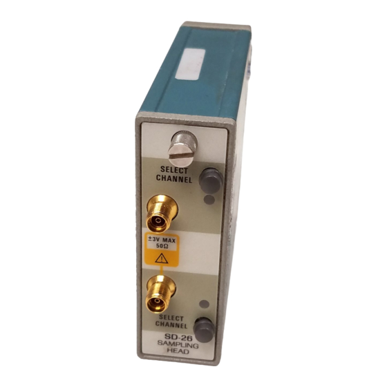
Connecting Signals
Connects signals for sampling, uses 3.5 mm connectors, 50 Ω input impedance.
Button and Lights Operation
Describes states of channel indicator lights and SELECT CHANNEL button operations.
Instrument and Sampling Head Interaction
Explains how the instrument controls sampling head functions like scaling and parameters.
Smoothing Functionality
Reduces noise by averaging samples; can be set via front panel or remote interface.
External Attenuation Setting
Allows entering external attenuation values for a channel via a command.
Displaying a Trace
Step-by-step guide to acquiring and displaying a trace using the sampling head and instrument.
Adjusting Sampling Head Parameters
Stored Parameter Values
Explains nonvolatile memory for factory defaults and user constants for parameters.
Loop Gain Description
Determines accuracy of voltage change tracking; affects dot transient response.
Adjusting Loop Gain
How to adjust loop gain automatically or manually using instrument features.
Offset Null Description
Removes unwanted DC offset to ensure accurate 0V output for 0V input.
Adjusting Offset Null
Manual and automatic procedures for adjusting offset null, noting smoothing parameter impact.
Need help?
Do you have a question about the SD-26 and is the answer not in the manual?
Questions and answers