
Related Manuals for Tektronix 1503C


Summary of Contents for Tektronix 1503C
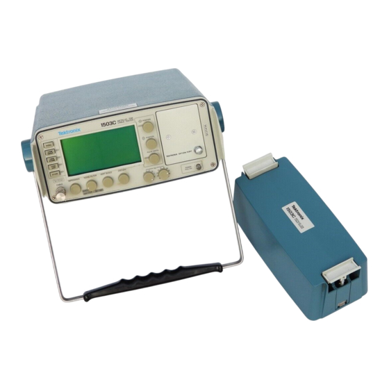
- Page 1 User Manual 1503C Metallic Time-Domain Reflectometer 070-7323-05 This document applies to firmware version 5.04 and above. www.tektronix.com...
- Page 2 Copyright Tektronix, Inc. All rights reserved. Tektronix products are covered by U.S. and foreign patents, issued and pending. Information in this publication supercedes that in all previously published material. Specifications and price change privileges reserved. Tektronix, Inc., P.O. Box 500, Beaverton, OR 97077...
- Page 3 Tektronix, with shipping charges prepaid. Tektronix shall pay for the return of the product to Customer if the shipment is to a location within the country in which the Tektronix service center is located.
-
Page 5: Table Of Contents
1–1 Preparing to Use the 1503C ......... - Page 6 ......... Index–1 1503C MTDR User Manual...
-
Page 7: List Of Figures
....1–3 Figure 1–3: 1503C Front-Panel Controls ...... - Page 8 ..2–19 Figure 2–32: Display with Pulse Turned Off ..... . 2–21 1503C MTDR User Manual...
- Page 9 ..........3–17 1503C MTDR User Manual...
-
Page 10: List Of Tables
..........A–5 1503C MTDR User Manual... -
Page 11: General Information
The 1503C generates a half-sine wave signal, applies it to the cable under test, and detects and processes the reflected voltage waveform. These reflections are displayed in the 1503C liquid crystal display (LCD), where distance measurements may be made using a cursor technique. -
Page 12: Installation And Repacking
Checks appendix. These checks should satisfy the requirements for most receiving or incoming inspections. Power Source and Power The 1503C is intended to be operated from a power source that will not apply more Requirements than 250 volts RMS between the supply conductors or between either supply conductor and ground. - Page 13 General Information Repacking for Shipment When the 1503C is to be shipped to a Tektronix Service Center for service or repair, attach a tag showing the name and address of the owner, name of the individual at your firm who may be contacted, the complete serial number of the instrument, and a description of the service required.
-
Page 14: Contacting Tektronix
This phone number is toll free in North America. After office hours, please leave a voice mail message. Outside North America, contact a Tektronix sales office or distributor; see the Tektronix web site for a list of offices. 1503C MTDR User Manual... -
Page 15: General Safety Summary
Do Not Operate Without Covers. Do not operate this product with covers or panels removed. Use Proper Fuse. Use only the fuse type and rating specified for this product. Avoid Exposed Circuitry. Do not touch exposed connections and components when power is present. 1503C MTDR User Manual... - Page 16 This product contains a Nickel Cadmium (NiCd) battery, which must be recycled or disposed of properly. For the location of a local battery recycler in the U.S. or Canada, please contact: RBRC (800) BATTERY Rechargeable Battery Recycling Corp. (800) 227-7379 P.O. Box 141870 www.rbrc.com Gainesville, Florida 32614 1503C MTDR User Manual...
-
Page 17: Operating Instructions
The carrying handle rotates 325 and serves as a stand when positioned beneath the instrument. The 1503C can be stored in temperatures ranging from –62 C to +85 C if a battery is not installed. If a battery is installed and the storage temperature is below –35 C or above +65 C, the battery pack should be removed and stored separately (see 1503C Service Manual for instructions on removing the battery). - Page 18 Operating Instructions The 1503C is intended to be operated from a power source that will not apply more than 250 V RMS between the supply conductors or between either supply conductor and ground. A protective ground connection by way of the grounding conductor in the power cord is essential for safe operation.
-
Page 19: Figure 1-2: Display Showing Low Battery Indication
If the battery is low, it will be indicated on the LCD (bat/low). If this is the case, protective circuitry will shut down the 1503C within minutes. Either switch to AC power or work very fast. If the instrument is equipped with a chart recorder, using the recorder will further reduce the battery level, or the added load might shut down the instrument. -
Page 20: Preparing To Use The 1503C
Operating Instructions When operating the 1503C in an environment below +10 C, a heater will activate. The element is built into the LCD module and will heat the display to permit normal operation. Depending on the surrounding temperature, it might take up to 15 minutes to completely warm the crystals in the LCD. -
Page 21: Display
Pulse Width Division Figure 1–4: Display and Indicators Front-Panel Controls 1. CABLE: A female BNC connector for attaching a cable to the 1503C for testing. IMPEDANCE 2. IMPEDANCE: A four-position rotary switch that selects the output impedance of the cable test signal. Available settings are 50, 75, 93, and 125 Ohms. The selected value is displayed above the control on the LCD. - Page 22 A standard instrument defaults to ft/div. A metric instrument (Option 05) defaults to m/div, but either may be changed temporarily from the menu. The default can be changed by changing an internal jumper (see 1503C Service Manual and always refer such changes to qualified service personnel).
-
Page 23: Menu Selections
Hold can be deactivated by pushing STORE or the mode exited by using the Setup Menu. ii. Pulse Is: On/Off. Turns the pulse generator off so the 1503C does not send out pulses. iii. Single Sweep Is: On/Off. This function is much like a still camera; it will acquire one waveform and hold it. - Page 24 When powered up, the instrument will default to feet unless the internal jumper has been moved to the meters position. Instructions on changing this default are contained in the 1503C Service Manual. d. Light Is: On/Off. This control turns the electroluminescent backlight behind the LCD on or off.
- Page 25 With user-developed software drivers, the ability to obtain detailed error messages during the development can be very useful. For more information, contact your Tektronix Customer Service representatives. They have information describing the option port hardware and software protocol and custom development methods available.
-
Page 26: Test Preparations
It is sometimes expressed as a whole number (e.g., 66) or a percentage (e.g., 66%). On the 1503C, it is the percentage expressed as a decimal number (e.g., 66% = .66). If you do not know the velocity of propagation, you can get a general idea from the following table, or use the Help with Cables section of the Cable Information menu. -
Page 27: Figure 1-5: Vp Set At .30, Cursor Beyond Reflected Pulse (Setting Too Low)
The Vp controls of the instrument are now set to the Vp of the cable. The following three illustrations show settings too low, too high, and correct for a sample three-foot cable. 3.00 ft Figure 1–5: Vp Set at .30, Cursor Beyond Reflected Pulse (Setting Too Low) 1–11 1503C MTDR User Manual... -
Page 28: Cable Test Procedure
Figure 1–7: Vp Set at .66, Cursor on Rising Edge of Reflected Pulse (Set Correctly) Cable Test Procedure Distance to the Fault Be sure to read the previous paragraphs on Vp. 1. Set the 1503C controls: POWER CABLE Cable to BNC... -
Page 29: Figure 1-8: 20-Ft Cable At 5 Ft/Div
Essentially, a drop in the pulse is a short and a rise in the pulse is an open. Less catastrophic faults can be seen as hills and valleys in the waveform. Bends and kinks, frays, water, and interweaving all have distinctive signatures. 0.00 ft Short Figure 1–9: Short in the Cable 1–13 1503C MTDR User Manual... -
Page 30: Figure 1-10: Open In The Cable
5. Change DIST/DIV to 20 ft/div. The entire cable can now be inspected in detail on the LCD. Turn the POSITION control so the cursor travels to the far right side of the LCD. Keep turning and the cable will be “dragged” across the display. 1–14 1503C MTDR User Manual... -
Page 31: Figure 1-12: 455-Ft Cable With 20 Ft/Div, Cursor Off Screen
Return Loss (in dB) = –20 * log (base ten) of Absolute Value of Rho (V To measure return loss with the 1503C, note the height of the incident pulse, then adjust the reflected pulse to be the same height that the incident pulse was and read the dB on the LCD display. -
Page 32: Figure 1-14: Reflection Adjusted To One Division In Height
In an ideal transmission system with no changes in impedance, there will be no reflections, so rho is equal to zero. A good cable that is terminated in its characteristic impedance is close to ideal and will appear as a flat line on the 1503C display. -
Page 33: Figure 1-15: Display With View Input Turned Off
It will show as a downward shift or dip on the waveform. If the cable has an open or short, all the energy sent out by the 1503C will be reflected. This is a reflection coefficient of rho = 1, or +1000 m for the open and –1000 m for the short. -
Page 34: Figure 1-16: Display Of A Stored Waveform
NOTE. If the two waveforms are identical (e.g., if STORE is pushed and VIEW DIFF is immediately pushed) the difference would be zero. Therefore you would see the difference waveform as a straight line. 1–18 1503C MTDR User Manual... -
Page 35: Figure 1-18: Display Of A Stored Waveform, Current Waveform, And Difference Waveform
2. Push STORE to capture the waveform. Remember, once it is stored, this waveform cannot be moved on the display. 3. Move the current waveform (the one you want to compare against the stored waveform) to the center of the display. 1–19 1503C MTDR User Manual... -
Page 36: Figure 1-20: Current Waveform Centered, Stored
The VIEW DIFF function is useful when you want to see any changes in the cable. In some systems, there might be several reflections coming back from each branch of the network. It might become necessary to disconnect branch lines from the cable 1–20 1503C MTDR User Manual... -
Page 37: Figure 1-22: Waveform Of Three-Foot Lead-In Cable
POSITION control to set the cursor where you want to start the distance reading. This will be the new zero reference point. For a three-foot lead-in cable, the cursor should be set at 3.00 ft. 1–21 1503C MTDR User Manual... -
Page 38: Figure 1-23: Cursor Moved To End Of Three-Foot Lead-In Cable
Turn DIST/DIV to 1 ft/div. If the distance reading is extremely high, you might want to use a higher setting initially, then turn to 1 ft/div for the next adjustment. c. Turn the POSITION control until the distance window reads 0.00 ft. 1–22 1503C MTDR User Manual... -
Page 39: Figure 1-25: Cursor Moved To 0.00 Ft
4. Return NOISE FILTER to the desired setting. Notice that the dB scale is now set to 0.00 dB. 5. To exit VERT SET REF, use the following procedure: a. Make sure the vertical scale is in dB mode (access the Setup Menu if change is needed). 1–23 1503C MTDR User Manual... -
Page 40: Additional Features (Menu Selected)
Additional Features (Menu Selected) Max Hold The 1503C will capture and store waveforms on an ongoing basis. This is useful when the cable or wire is subjected to intermittent or periodic conditions. The 1503C will monitor the line and display any fluctuations on the LCD. -
Page 41: Figure 1-28: Waveform Showing Intermittent Short
Hold, and push MENU repeatedly until the instrument returns to normal operation. Pulse On/Off This feature puts the 1503C in a “listening mode” by turning off the pulse generator. 1. Attach a cable to the 1503C front-panel CABLE connector. 2. Push MENU to access the Main Menu. - Page 42 This feature allows the 1503C to act much like a non-triggered oscilloscope. In this mode, the 1503C is acting as a detector only. Any pulses detected will not originate from the instrument, so any distance readings will be invalid. If you are listening to a local area network, for example, it is possible to detect traffic, but not possible to measure the distance to its origin.
-
Page 43: Operator Tutorial
You, the Operator The 1503C is a highly accurate cable tester. It is easy to use and will provide fast, accurate measurements. Because of electrical and environmental differences in cables and their applications, each waveform will likely differ. The best way to learn these differences is experience with the instrument. -
Page 44: Getting Started
Getting Started Let’s start by inspecting a cable. For the next few examples, we will use the 93 10-foot precision test cable provided with the 1503C (Tektronix part number 012-1351-00). 1. Pull on the POWER switch. The instrument will initialize, give instructions for accessing the menu, and enter normal operation mode. -
Page 45: Pulse (Set Correctly)
6. Short the end of the cable with an electrical clip or other suitable device. See the pulse take a dive? That is the classic signature of a short, a point of lower impedance. 2–3 1503C MTDR User Manual... -
Page 46: The Waveform Up Close
POSITION control counterclockwise until the distance window reads –2.00 ft. The cursor will be on the far left side of the display and the reflected pulse will be near center. –2.00 ft Figure 2–5: 10-foot Cable with Cursor at Far Left 2–4 1503C MTDR User Manual... - Page 47 Operator Tutorial 2. Set the 1503C front-panel controls: CABLE 10-ft test cable, no short IMPEDANCE NOISE FILTER 1 avg VERT SCALE 0.00 dB DIST/DIV 1 ft (0.25 m) PULSE WIDTH 2 ns 3. The first (left) pulse is the incident pulse, as sent from the pulse generator (see Figure 2–2).
-
Page 48: A Longer Cable
Obtain a known length of cable, preferably 50 . For this example, we are using a coaxial cable approximately 455 feet long. Your cable length will probably differ, but the following test procedure remains fundamentally correct for any cable length up to 50,000 feet. 1. Set the 1503C front-panel controls: CABLE available longer cable IMPEDANCE... - Page 49 456.00 ft Figure 2–10: Pulse Width at 2 ns 8. Set PULSE WIDTH to 10 ns. The pulse height increases because there is more energy being sent through the cable. 2–7 1503C MTDR User Manual...
- Page 50 When the PULSE WIDTH control is set to Auto, the instrument automatically sets the pulse width in relation to the distance on the right side of the display. The following table shows the relationship between the distance on the display and the Auto pulse width. 2–8 1503C MTDR User Manual...
-
Page 51: Noise
Noise On a longer cable, “grass” might appear on the displayed waveform. This is primarily caused by the cable acting as an antenna, picking up nearby electrical noise. 1. Set the 1503C front-panel controls: CABLE 10-ft cable IMPEDANCE NOISE FILTER... - Page 52 Because there are no large discontinuities, it appears to the instrument as an endless cable. The noise seen in this demonstration is noise picked up on the cable and a tiny amount of internal noise in the 1503C. When testing cables, the noise filter is extremely effective in reducing noise.
-
Page 53: Set Ref ( Mode)
If, for example, you have a 10-foot cable leading to a patch panel, you could eliminate this jumper from your distance readings. 1. Set the 1503C front-panel controls to: CABLE Attach 10-ft cable... - Page 54 This control is nearly the same as HORZ SET REF except it sets the vertical zero reference. It would be helpful to read the section of VERT SET REF in the Operation Instructions chapter to give you some technical background. 2–12 1503C MTDR User Manual...
- Page 55 The VERT SET REF function allows manual control of the vertical calibration of the 1503C. This can be used to compensate for cable loss or to increase the resolution of the return loss measurements. The following example shows how to compensate for cable loss.
-
Page 56: View Input
Return the NOISE FILTER control to the desired setting. VIEW INPUT This push button allows you to view what is coming in the CABLE connector, or to eliminate it from the display. 1. Set the 1503C front-panel controls to: CABLE Attach 10-ft cable IMPEDANCE... -
Page 57: Store And View Store
This function can be used to make the display less busy when viewing stored waveforms. STORE and VIEW STORE These functions allow you to store a waveform and view the stored waveform. 1. Set the 1503C front-panel controls to: CABLE Attach 10-ft cable IMPEDANCE... - Page 58 Figure 2–26: Waveform with Cable Shorted 6. Press VIEW STORE to view the stored waveform. What you see on the display is the waveform you stored previously with the open cable and the current waveform with the shorted cable. 2–16 1503C MTDR User Manual...
-
Page 59: View Diff
DIFF function. Pressing this button with no waveform in storage will caused an error message to be displayed. If the stored waveform and the current waveform are identical, the difference waveform will appear as a straight line. 2–17 1503C MTDR User Manual... -
Page 60: Menu-Accessed Functions
Menu-Accessed Functions NOTE. If you get lost or confused while in a menu, repeatedly press the MENU button until the instrument returns to normal operation mode. Max Hold 1. Set the 1503C front-panel controls to: CABLE Attach 10-ft cable IMPEDANCE... - Page 61 Figure 2–30: Short and Open Viewed via Max Hold 16. Turn the POSITION control counterclockwise. THe waveform will strobe down the display, leaving traces of its movement. 0.00 ft Figure 2–31: Waveform Strobed Down Display in Max Hold 2–19 1503C MTDR User Manual...
- Page 62 18. To exit Max Hold, access the Acquisition Control Menu again, turn off Max Hold, and push MENU repeatedly until the instrument returns to normal operation. Pulse On / Off 1. Set the 1503C front-panel controls to: CABLE Attach 10-ft cable IMPEDANCE...
- Page 63 0.00 ft Figure 2–32: Display with Pulse Turned Off Note that there is no pulse visible on the display. The 1503C is now functioning as a listening device, much like a non-triggered oscilloscope. Uses include monitoring the cable for pulses.
- Page 64 0.00 ft Figure 2–33: Test Cable 11. Short the far end of the test cable. 12. Press VIEW INPUT. The 1503C has done a single sweep, capturing just one frame. 0.00 ft Figure 2–34: Shorted Test Cable with a Captured Single Sweep 13.
-
Page 65: Tdr Questions And Answers
1 ns/ft in a vacuum would mean a distance of 15 feet. Because the cable is slower, we multiply the distance by the Vp (.66 in this case) and arrive at a distance of 10 feet. Of course, the 1503C does all this automatically and displays the information on the LCD. - Page 66 Q12: Why should cables of the same impedance be used? A12: Because a mismatch of impedance means a loss of energy at the mismatch. Q13: Why is that important to us? A13: Because a TDR displays the energy reflected back from an impedance mismatch. 2–24 1503C MTDR User Manual...
-
Page 67: Options And Accessories
Option 06: Ethernet Option 06 instruments include circuitry that allows the 1503C to test an Ethernet bus using time-domain reflectometry with minimum disruption to the IEEE 802.3 protocol. - Page 68 Servers let a network share resources, such as terminals, disks, printers, etc. The 1503C with Option 06 allows testing of an Ethernet bus while the network is active. This is important because some installations might be interactive with other installations that are dependent on the Ethernet.
- Page 69 Before Starting, here are some things you should know to make Ethernet tests easier: Working Network You need Option 06 for testing an active network. Make measurements from the end of a segment. If possible, isolate the segment you plan to test. 3–3 1503C MTDR User Manual...
- Page 70 The third test, Carrier Test is: Off/On, helps track down transceivers suspected if ignoring the carrier sense signal. This test holds the carrier signal of -1.05 V, turns off the pulse, and turns on MAX HOLD. The 1503C then acts as a traffic monitor. 3–4...
- Page 71 On. When performing other Ethernet tests, use essentially the same procedure. A full description of individual tests, including custom tests, follows: If you wish to disconnect and reconnect the 1503C to the cable segment, use a BNC T-connector between the instrument and a 50 jumper cable (e.g., RG-58U).
- Page 72 Female type N Ethernet Ethernet Figure 3–3: N-Type Female T-Connector 1. Before removing the Ethernet cable terminator, make sure you have the correct adapters and cables ready. 2. Set the 1503C front-panel controls: CABLE see below IMPEDANCE NOISE FILTER 1 avg...
- Page 73 This entry is a duplicate of the entry in the Setup Menu/Acquisition Control Menu. Its function is to allow direct control of the termination inside the 1503C. With the DC termination on, the 1503C will function normally as a cable tester. This is usually the only test needed to check a network cable.
- Page 74 When this test is selected, the 1503C will assert a -1.05 VDC signal on the net long enough to take a single waveform at the NOISE FILTER level selected. This is the equivalent to the average voltage level of a normal transmission and should cause the transceivers to assert Carrier Detect.
- Page 75 CAUTION. The carrier signal will stop most traffic on the network. This might abort many application programs and might cause communications problems. When this test is on, the 1503C will assert a -1.05 VDC level on a 50 load (-2.1 VDC open circuit).
- Page 76 CAUTION. The collision signal will stop most traffic on the network. This might abort many application programs and might cause communications problems. When this test is on, the 1503C will assert a -1.7 VDC level on a 50 load (-3.4 VDC open circuit).
- Page 77 (1 avg, 50 ft/div. 35 dB) 173.36 ft Figure 3–5: System 1 - Traffic and Tap Nearly Identical (4 avg, 50 ft/div, 35 dB) 173.36 ft Figure 3–6: System 1 - Tap Becoming Visible (16 avg, 50 ft/div, 35 dB) 3–11 1503C MTDR User Manual...
- Page 78 (128 avg, 50 ft/div, 35 dB) 173.36 ft Figure 3–8: System 1 - No Traffic (1 avg, 50 ft/div, 35 dB) 167.56 ft Figure 3–9: System 1 - Tap Expanded, No Traffic (1 avg, 2 ft/div, 35 dB) 3–12 1503C MTDR User Manual...
- Page 79 1503C. This creates an unusual waveform that looks similar to data. As a rule, repeaters should be shut down prior to testing a segment to prevent such occurrences.
- Page 80 742.52 ft Figure 3–14: System 2 - Farther Out, More Gain (128 avg, 10 ft/div, 53.5 dB) 714.12 ft Figure 3–15: System 2 - 1000-ft Cable at 10 ns (128 avg, 100 ft/div, 43.75 dB) 3–14 1503C MTDR User Manual...
- Page 81 (128 avg, 20 ft/div, 54.75 dB) 1116.84 ft Figure 3–17: System 2 - Next Group of Taps (128 avg, 20 ft/div, 54.75 dB) 1034.44 ft Figure 3–18: System 2 - Group of Taps Expanded (128 avg, 10 ft/div, 54.75 dB) 3–15 1503C MTDR User Manual...
- Page 82 Once the termination is turned on, it will remain on until specifi- cally turned off by the operator, at which time a warning to remove the 1503C from the network will be shown on the display. Leaving the TDR on the net- work with the termination turned off will cause traffic disruption and errors.
-
Page 83: Option 07: Yt-1S Chart Recorder
Option 08: Token Ring Adapter Option 08 instruments come with an adapter that allows you to connect the 1503C to networks containing ECL connectors. The adapter isolates the receive pair from the transmit pair at the ECL connector and allows you to select one or the other to be routed to the input BNC connector on the 1503C. -
Page 84: Option 09: Universal Service Ordering Code
Options and Accessories Option 09: Universal Service Ordering Code Option 09 instruments come with an adapter that allows you to connect the 1503C to LANs using type RJ-45 connectors using the Universal Service Ordering Code. The adapter allows selection of each of the four twisted pairs. -
Page 85: Accessories
....103-0035-00 Connector, BNC male to N female ..... . 103-0058-00 3–19 1503C MTDR User Manual... - Page 86 Token Ring Interface ....... . . 015-0600-00 3–20 1503C MTDR User Manual...
-
Page 87: Appendix A: Specifications
–30 dB p–p for 10 ns, 100 ns, 1000 ns test Within three test pulse widths after test pulse. pulse dB is relative to test pulse. –25 dB p–p for 2 ns test pulse (continued next page) A–1 1503C MTDR User Manual... - Page 88 Accuracy within Custom Option Port Tek chart recorder is designed to operate with the 1503C. Produces a high resolution thermal dot matrix recording and waveform and control values. Line Voltage 115 VAC (90 to 132 VAC) 45 to 440 Hz Fused at 0.3 A...
-
Page 89: Environmental Characteristics
Withstand 48 hours, 20% solution without corrosion Sand and Dust Operates after test with cover on, non-operating MIL–STD–810, Method 510, Procedure I Washability Capable of being washed Fungus Inert Materials are fungus inert (continued next page) A–3 1503C MTDR User Manual... -
Page 90: Certifications And Compliances
CAT II Local-level mains (wall sockets). Equipment at this level includes appliances, portable tools, and similar products. Equipment is usually cord-connected. CAT I Secondary (signal level) or battery operated circuits of electronic equipment. (continued next page) A–4 1503C MTDR User Manual... -
Page 91: Physical Characteristics
Height 5.0 inches (127 mm) Width with handle 12.4 inches (315 mm) without handle 11.8 inches (300 mm) Depth with cover on 16.5 inches (436 mm) with handle extended to front 18.7 inches (490 mm) A–5 1503C MTDR User Manual... - Page 92 Appendix A: Specifications A–6 1503C MTDR User Manual...
-
Page 93: Appendix B: Operator Performance Checks
Appendix B: Operator Performance Checks This appendix contains performance checks for many of the functions of the 1503C. They are recommended for incoming inspections to verify that the instrument is functioning properly. Procedures to verify the actual performance requirements are provided in the 1503C Service Manual. - Page 94 If the instrument fails this check, it must be repaired before any distance (Timebase) Check measurements can be made with it. 1. Turn the 1503C power on. The display should look very similar to Figure B–1. 0.00 ft Figure B–1: Start-up Measurement Display 2.
- Page 95 3.50 to 3.70 feet (1.05 to 1.11 m). 3.60 ft Figure B–4: Cursor at End of 10-foot Cable, Vp Set to .30 5. Remove the 10-foot cable and connect the 50 terminator. Change the 1503C front-panel controls to: VERT SCALE 0.00 dB...
- Page 96 2. Using the POSITION control, verify that the entire waveform can be moved to the very bottom of the display (to the bottom graticule line). 50600.00 ft Waveform Figure B–7: Waveform at the Bottom of the Display B–4 1503C MTDR User Manual...
- Page 97 If the instrument fails this check, it should not be used for loss or impedance measurements. Send it to be serviced when possible. 1. In the Service Diagnostic Menu, select the Offset/Gain Diagnostic and follow the directions on the display. B–5 1503C MTDR User Manual...
- Page 98 If the aberrations are too large, they can be confused with minor faults in the cable near the instrument. 1. Turn the POSITION control counterclockwise until the display distance window reads less than 20.00 ft (6.10 m). 2. Set the DIST/DIV control to 1 ft/div (0.25 m/div). B–6 1503C MTDR User Manual...
- Page 99 Appendis B: Operator Performance Checks –2.00 ft Figure B–9: Distance at –2.00 ft 3. Turn the POSITION control counterclockwise until the display distance window reads –2.00 ft (–0.62 m). 4. Set the 1503C front-panel controls: IMPEDANCE NOISE FILTER 1 avg VERT SCALE 0.00 dB...
- Page 100 16. Turn PULSE WIDTH to 10 ns. 17. Adjust the pulse height to four major divisions. –2.00 ft Figure B–12: Pulse Adjusted to Four Major Divisions in Height 18. Press STORE. 19. Return the NOISE FILTER control to 1 avg. B–8 1503C MTDR User Manual...
- Page 101 26. Turn PULSE WIDTH to 100 ns. 27. Adjust the pulse height to four major divisions. –2.00 ft Figure B–14: Pulse Adjusted to Four Major Divisions in Height 28. Press STORE. 29. Return the NOISE FILTER control to 1 avg. B–9 1503C MTDR User Manual...
- Page 102 Figure B–16: Pulse Adjusted to Four Major Divisions in Height 38. Press STORE. 39. Return the NOISE FILTER control to 1 avg. 40. Place the baseline of the waveform on the center graticule using the POSITION control. B–10 1503C MTDR User Manual...
- Page 103 If you suspect a problem of this nature, you should have the instrument checked by a qualified service technician, using the diagnostics in the 1503C Service Manual. If the instrument passed all of the previous checks, it is ready for use.
- Page 104 Appendis B: Operator Performance Checks B–12 1503C MTDR User Manual...
-
Page 105: Appendix C: Operator Troubleshooting
Appendix C: Operator Troubleshooting For assistance in troubleshooting, use the following flow chart to determine if you have a simple problem you can fix or if the instrument needs to be sent to a Tektronix Service Center. C–1 1503C MTDR User Manual... - Page 106 Appendix C: Operator Troubleshooting Operator Troubleshooting (with cases on) C–2 1503C MTDR User Manual...
-
Page 107: Error Messages
If the error persists, have the TDR serviced. Message: ERROR: Acquisition Initialization TYPE: Leading edge of pulse not found ERROR: Acquisition Initialization TYPE: Top of 50nsec ramp not found C–3 1503C MTDR User Manual... - Page 108 This could be because the pulse is not there, or because the sampler or gain circuitry is broken, or even because the timebase is not functioning properly. Remedies: The instrument must be sent to service for repair. C–4 1503C MTDR User Manual...
-
Page 109: Appendix D: Application Note
Introduction Most people who make quantitative reflectometry tests or measurements should find the Tektronix TDR Slide Rule helpful. Those new to the subject will find the slide rule graphically summarizes a wealth of information on reflectometry. Voltage Standing Wave Ratio vs. Percent Reflected Voltage Return Loss, dB, vs. - Page 110 NOTE. The relationship between % holds only when the loss is a single impedance discontinuity with negligible capacitive or inductive components (e.g., a 75 termination at the end of a 50 cable). The VSWR must be essentially the same for all sine-wave frequencies. D–2 1503C MTDR User Manual...
- Page 111 Select the side of the slide rule that corresponds to the source resistance (R ) of the generator used, then select the longest scale as follows: D–3 1503C MTDR User Manual...
- Page 112 Then count off the right number of divisions and subdivisions to locate the level corresponding to the peak of the reflection and read the corresponding impedance levels (Ohms) on the adjacent sliding scale. D–4 1503C MTDR User Manual...
- Page 113 If the load resistance is known, the previous procedures can be used to approximate the size of the return reflection. An error might be introduced if the impedance of the connecting cable does not match the source resistance of the pulse generator. D–5 1503C MTDR User Manual...
- Page 114 2) If the risetime of the TDR system is too long, a reflection with a plateau will appear as a spike. D–6 1503C MTDR User Manual...
- Page 115 For distances less than about three meters (or 10 feet), use the INCHES and CENTIMETERS scale. D–7 1503C MTDR User Manual...
- Page 116 1.0 1.5 2.0 3 4 5 6 DIELECTRIC Polyethylene CONSTANT ROUND Time = 300 ns TRIP 00ns 150ns 200ns 300ns 500ns 700n TIME Velocity Factor = .66 VELOCITY FACTOR .8 .7 Figure D–8: Dielectric Constant and Velocity Factor, Long Distance D–8 1503C MTDR User Manual...
-
Page 117: Glossary
Cables are designed to match the source and load for the electrical energy that they carry. The designed impedance is often called the characteristic impedance of the cable. The arrangement of the conductors with respect to each other is the major factor in designing the impedance of cables. Glossary–1 1503C MTDR User Manual... - Page 118 The pulse of electrical energy sent out by the TDR. The waveform shown by the TDR consists of this pulse and the reflections of it coming back from the cable or circuit being tested. Inductance (see Reactance) Glossary–2 1503C MTDR User Manual...
- Page 119 More waveforms in an average are more likely to approach the real signal (although it takes longer to acquire and add together more waveforms). Glossary–3 1503C MTDR User Manual...
- Page 120 AC waveform. Sampling Efficiency Our instruments make measurements by taking a succession of samples in time and displaying them as a waveform with voltage on the vertical scale (up and down) and Glossary–4 1503C MTDR User Manual...
- Page 121 (so it is always a number between 0 and 1). A velocity of propagation value of 0.50 indicates that the electrical energy moves through the cable at half the speed of light. Waveform Averaging (see Noise) Glossary–5 1503C MTDR User Manual...
- Page 122 Glossary Glossary–6 1503C MTDR User Manual...
-
Page 123: Index
Introduction, 3–4 Checks (see Performance Checks) Menu, 3–7 Collision, 3–2 Carrier, 3–8 Connectors Collision, 3–9 BNC – BNC, 3–19 Single Sweep, 3–8 BNC to Alligator, 3–19 Termination, 3–7 BNC to Banana, 3–19 N-Type Female T-Connector, 3–6 Index–1 1503C MTDR User Manual... - Page 124 Noise (see also Controls), 1–5, 2–9 Isolation Network, 3–20 Reduced, 2–10 Noise Filter, 2–11, 2–12, 2–13 Noise Spec, A–1 Loss, 1–15 Open, 1–14, 2–3 Option Port Cover, 3–19 Maintenance, C–1, D–1 Max Hold (see Maximum Hold), 2–18 Index–2 1503C MTDR User Manual...
- Page 125 1000ns, 2–8 Transceivers, 3–1 100ns, 2–8 Troubleshooting, C–1 10ns, 2–8 Tutorial, 2–1 2ns, 2–7 Incident, 2–3, 2–5, 2–11, 2–12 Reflected, 2–3, 2–11, 2–12 Pulse Inverter, 3–20 Pulse Spec, A–1 USOC Adapter, 3–20 Questions and Answers, 2–23 Index–3 1503C MTDR User Manual...
- Page 126 Vertical Scale Spec, A–1 Water Resistance Spec, A–3 Vertical Set Reference, 1–23, 2–12 Waveform Storage, 1–18 Vibration Spec, A–3 Weight Spec, A–5 View Diff (see View Difference) What is a 1503C?, 2–1 View Difference, 1–18, 2–17 Index–4 1503C MTDR User Manual...
Need help?
Do you have a question about the 1503C and is the answer not in the manual?
Questions and answers