Table of Contents
Advertisement
Quick Links
Download this manual
See also:
Instruction Manual
Service Manual
P6701B, P6703B & P6723
O/E Converters
070-9892-03
Warning
The servicing instructions are for use by qualified
personnel only. To avoid personal injury, do not
perform any servicing unless you are qualified to
do so. Refer to all safety summaries prior to
performing service.
*P070989203*
070989203
Advertisement
Table of Contents

Related Manuals for Tektronix P6701B


Summary of Contents for Tektronix P6701B
- Page 1 Service Manual P6701B, P6703B & P6723 O/E Converters 070-9892-03 Warning The servicing instructions are for use by qualified personnel only. To avoid personal injury, do not perform any servicing unless you are qualified to do so. Refer to all safety summaries prior to performing service.
- Page 2 Copyright © Tektronix, Inc. All rights reserved. Tektronix products are covered by U.S. and foreign patents, issued and pending. Information in this publication supercedes that in all previously published material. Specifications and price change privileges reserved. Tektronix, Inc., P.O. Box 500, Beaverton, OR 97077...
- Page 3 Tektronix, with shipping charges prepaid. Tektronix shall pay for the return of the product to Customer if the shipment is to a location within the country in which the Tektronix service center is located. Customer shall be responsible for paying all shipping charges, duties, taxes, and any other charges for products returned to any other locations.
- Page 4 H Eliminates unexpected service expenses For Information and Ordering For more information or to order Service Assurance, contact your Tektronix representative and provide the information below. Service Assurance may not be available in locations outside the United States of America.
-
Page 5: Table Of Contents
..........Contacting Tektronix . - Page 6 Table of Contents P6701B, P6703B, and P6723 Service Manual...
-
Page 7: General Safety Summary
General Safety Summary Review the following safety precautions to avoid injury and prevent damage to this product or any products connected to it. To avoid potential hazards, use this product only as specified. Only qualified personnel should perform service procedures. To Avoid Fire or Observe All Terminal Ratings. - Page 8 General Safety Summary Symbols on the Product. The following symbols may appear on the product: WARNING Protective Ground CAUTION Double High Voltage (Earth) Terminal Refer to Manual Insulated P6701B, P6703B, and P6723 Service Manual...
-
Page 9: Preface
This phone number is toll free in North America. After office hours, please leave a voice mail message. Outside North America, contact a Tektronix sales office or distributor; see the Tektronix web site for a list of offices. P6701B, P6703B, and P6723 Service Manual... - Page 10 Preface P6701B, P6703B, and P6723 Service Manual...
-
Page 11: P6701B And P6703B Specifications
P6701B and P6703B Specifications The specifications in Tables 1 through 3 apply to a P6701B or P6703B O/E converter. The converter must have a warm-up period of at least 20 minutes and be in an environment that does not exceed the limits described in Table 1. Specifications for the P6701B and P6703B O/E converters fall into three categories: warranted, typical, and nominal characteristics. -
Page 12: Typical Characteristics
P6701B and P6703B Specifications Table 1: P6701B and P6703B warranted electrical characteristics (cont.) Humidity Operating: 0- - 90% RH, tested at + 30 to + 50_ C Nonoperating: 0- - 90% RH, tested at + 30 to + 60_ C Altitude Operating: 4,572 m (15,000 ft) Nonoperating: 15,240 m (50,000 ft) - Page 13 P6701B and P6703B Specifications P6701B Normalized to 780nm at 1 V/mW ~ 0.8 at 850nm 1000 Wavelength (nm) P6703B ~ 1.1 at 1550 nm Normalized to 1310nm at 1 V/mW 1000 1200 1400 1600 Wavelength (nm) Figure 1: Typical wavelength dependent gain (25_ C ambient) P6701B, P6703B, and P6723 Service Manual...
-
Page 14: Nominal Characteristics
P6701B and P6703B Specifications Nominal Characteristics Nominal characteristics (Table 3) describe guaranteed traits, but the traits do not have tolerance limits. Table 3: P6701B and P6703B nominal electrical characteristics Accepts up to 62.5 m core diameter, Numerical Aperture ≤ 0.29 Optical input coupling Optical fiber dressing >... -
Page 15: P6723 Specifications
P6723 Specifications The specifications in Tables 4 through 6 apply to a P6723 O/E converter. The converter must have a warm-up period of at least 20 minutes and be in an environment that does not exceed the limits described in Table 4. Specifications for the P6723 O/E converter fall into three categories: warranted, typical, and nominal characteristics. -
Page 16: Typical Characteristics
P6723 Specifications Typical Characteristics Typical characteristics (Table 5) describe typical but not guaranteed performance. Table 5: P6723 typical electrical characteristics Effective wavelength range 1100 to 1570 nm ≤ ± 15%, 20% Aberrations total Nominal Characteristics Nominal characteristics (Table 6) describe guaranteed traits, but the traits do not have tolerance limits. -
Page 17: P6701B And P6703B Performance Verification
P6701B and P6703B Performance Verification Use the following procedures to verify the warranted specifications of the P6701B and P6703B O/E converters. Before beginning these procedures, refer to page 12 and photocopy the test record and use it to record the performance test results. -
Page 18: Noise Equivalent Power
Adjustable optical 4 decades, 50um core fiber, FC- JDS 5000L with 62 m attenuator style connectors fiber with FC connectors Digital voltmeter 4 1/2 digit Tektronix DMM916 ± 1% 50 ohm termination 011-0049-01 Optical cable FC-FC multimode, 62.5um, 2 174-2322-00 meters... -
Page 19: Output Zero
P6701B and P6703B Performance Verification Output Zero 1. Attach 1103 powered P670XB output to voltmeter with 50 ohm termination. 2. Install optical dust cover on input to P670XB under test. 3. Check that output voltage is ≤ 1 mV. DC Conversion Gain NOTE. -
Page 20: Ac Conversion Gain
P6701B and P6703B Performance Verification P6703B 1. Connect 1310 nm laser to attenuator. NOTE. The longer wavelengths of 1310 nm and especially 1550 nm are more sensitive to loss in fiber due to bending of the fiber than the short wavelength. The fiber bend radius of the P670XB fiber input should lay with >1-inch bend radius along the fiber’s entire length. - Page 21 P6701B and P6703B Performance Verification 3. Set the oscilloscope for 5 us/div on the horizontal scale and 5 mV/div (or 5 uW/div) for the vertical scale. Trigger the scope on the negative edge of the trace and set ground to the middle of the screen. This is equivalent to 1%/div.
- Page 22 P6701B and P6703B Performance Verification Test record Probe Model/Serial Number: Certificate Number: Temperature: RH %: Date of Calibration: Technician: Performance test Minimum Incoming Outgoing Maximum 15 nW (P6701B) Noise Equivalent Power 7 nW (P6703B) Output zero 1 mV DC conversion gain 92 mV 108 mV AC conversion gain...
-
Page 23: P6723 Performance Verification
5 pW, Max power > 1 mW, cali- sensor HP 81530A and brated from 700 nm - - 1600 nm HP 81531A 1310 nm digital optical 52 MHz - - 622 MHz Tektronix CTS710/CTS750 signal source Sampling oscilloscope oscilloscope with Tekprobe II Tektronix TDS784x interface... -
Page 24: Output Amplitude
P6723 Performance Verification Output Amplitude NOTE. Make sure that the optical connector ends of both the fiber jumpers and the input fiber of the O/E converter under test are well cleaned before perform- ing this step. Use isopropyl alcohol, lint-free lense paper and clean compressed air to clean the fiber ferrule ends. - Page 25 P6723 Performance Verification Test record Probe Model/Serial Number: Certificate Number: Temperature: RH %: Date of Calibration: Technician: Performance test Minimum Incoming Outgoing Maximum 0.69 V 1.1 V Output Amplitude P6701B, P6703B, and P6723 Service Manual...
- Page 26 P6723 Performance Verification P6701B, P6703B, and P6723 Service Manual...
-
Page 27: Maintenance
Maintenance To keep the P6701B, P6703B, and P6723 O/E Converters in good operating condition, observe proper cleaning and handling techniques. Cleaning the Optical Connectors Small dust particles and oils can easily contaminate fiber-optic connectors and reduce or block the signal. Take care to preserve the integrity your connectors by keeping them free of contamination. -
Page 28: Cleaning The External Parts
Maintenance NOTE. Cleaning kits for fiber-optic connectors are available from a number of suppliers. Cleaning the External Parts Remove dirt with a soft cloth dampened in a mild detergent and water solution or isopropyl alcohol. CAUTION. To avoid damaging the probe, use only a mild detergent and water solution or isopropyl alcohol;... -
Page 29: Replacing Tekprobe Interface Pins
Maintenance CAUTION. To maintain the high performance (low return loss) of the O/E converter, connect an adapter and cable between the input of the O/E converter and the device under test. When you make connections to other devices, leave the adapter and cable in place to protect the optical connector of the O/E converter from wear. -
Page 30: Removing And Replacing The Tekprobe Interface Collar
Maintenance Short pin Figure 3: Location of short interface pin Removing and Replacing the TekProbe Interface Collar 1. To remove the collar, firmly pull the collar off by hand. 2. To replace the collar, align the smaller group of pins with the smaller of the two holes in the interface collar and align the tabs with the slots. -
Page 31: Options
Options Option 95 documents the measurements taken during calibration. Option FR documents the frequency response of the O/E converter. P6701B, P6703B, and P6723 Service Manual... - Page 32 Options P6701B, P6703B, and P6723 Service Manual...
-
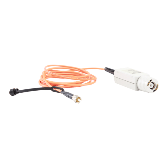
Page 33: Replaceable Parts
Replaceable Parts NOTE: Parts illustrated with dashed lines are not replaceable Figure 5: Replaceable parts Figure 6: Standard accessories Figure 7: Optional accessories P6701B, P6703B, and P6723 Service Manual... -
Page 34: Replaceable Parts List
Replaceable Parts Replaceable parts list Fig. & Tektronix Serial no. Serial no. index number part number effective discont’d Name & description Mfr. code Mfr. part number 5- - 1 131- - 3627- - 01 CONTACT,ELEC:GOLD PLATED TIP 18359 P- - 6158- - 1... - Page 35 PO BOX 547 62712 SEIKO INSTRUMENTS USA INC ELECTRONIC COMPONENTS DIV TORRANCE, CA 90505 2990 W LOMITA BLVD 80009 TEKTRONIX INC 14150 SW KARL BRAUN DR BEAVERTON, OR 97077- - 0001 PO BOX 500 TK2469 UNITREK CORPORATION 3000 LEWIS & CLARK HWY...
- Page 36 Replaceable Parts P6701B, P6703B, and P6723 Service Manual...
Need help?
Do you have a question about the P6701B and is the answer not in the manual?
Questions and answers