
Related Manuals for Tektronix SD-42


Summary of Contents for Tektronix SD-42
- Page 1 (217) 352-9330 | Click HERE Find the Tektronix SD-24 at our website:...
- Page 2 User Manual SD-42 & SD-46 Optical to Electrical Converter Heads 070-8671-01...
- Page 3 Copyright E Tektronix, Inc. 1992. All rights reserved. Tektronix products are covered by U.S. and foreign patents, issued and pending. Information in this publication supercedes that in all previously published material. Specifications and price change privileges reserved. Printed in the U.S.A.
- Page 4 Tektronix, with shipping charges prepaid. Tektronix shall pay for the return of the product to Customer if the shipment is to a location within the country in which the Tektronix service center is located.
-
Page 6: List Of Tables
........C–2 Index SD-42 & SD-46 User Manual... -
Page 7: Table Of Contents
......... B–1 Table B–2: SD-42 Optical-to-Electrical Converter Head Power Meter Characteristics . - Page 8 CAUTION. Caution statements identify conditions or practices that could result in damage to this product or other property. Terms on the Product These terms may appear on the product: DANGER indicates an injury hazard immediately accessible as you read the marking. SD-42 & SD-46 User Manual...
- Page 9 CAUTION indicates a hazard to property including the product. Symbols on the Product The following symbols may appear on the product: Double DANGER Protective Ground ATTENTION Insulated High Voltage (Earth) Terminal Refer to Manual SD-42 & SD-46 User Manual...
- Page 10 Getting Started...
- Page 12 CSA 803 Communications Signal Analyzer. The SD-42/SD-46 Optical-to- Electrical Converter Heads are used with SD-22, SD-24, and SD-26 Sampling Heads. The SD-42/SD-46 converts an optical signal into an electrical signal which serves as the input to an SD Series Sampling Head.
- Page 13 For best repeatability and to prolong the life of connectors, use a torque wrench and tighten the connection to the range of 7–10 lb-in (79–112 N-cm). The front of the SD-42/SD-46 has a precision FC/PC optical connector receptacle. This is for attaching a fiber optic signal cable. This connector receptacle has a locating keyway.
-
Page 14: Figure 1-1: Sampling Head Compartments In A Csa 803
For the converted output signal from the SD-42/SD-46 to be sampled, the output of the SD-42/SD-46 must be connected to the input of an SD-24 or SD-26 Sampling Head (the SD-42 can also be connected to an SD-22). To accomplish this using the U-link provided with the SD-42/SD-46, the SD-24 or SD-26 must be in the plug-in slot immediately to the right of the slot occupied by the SD-46. - Page 15 Getting Started 1–4 SD-42 & SD-46 User Manual...
- Page 16 Operating Basics...
-
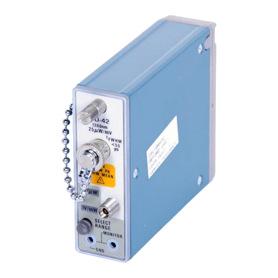
Page 18: Figure 2-1: Sd-42 Front Panel
A fiber terminated by an FC/PC style connector is connected to the FC/PC style input on the front of the SD-42/46. Care must be taken to ensure alignment of the key on the FC/PC connector with the keyway of the connector receptacle. - Page 19 The two 2 mm MONITOR sockets on the front of the SD-42/46 can be connected to most common digital voltmeters using the two 2 mm to 4 mm cables supplied with the SD-42/46.
- Page 20 1200 nm to 1650 nm can be analyzed using the SD-46 with the responsivity as a function of wavelength being given in Figure B–4. This responsivity curve is applicable to both the displayed wave- form and the mean power monitor output. 2–3 SD-42 & SD-46 User Manual...
- Page 21 Operating Basics 2–4 SD-42 & SD-46 User Manual...
- Page 22 Reference...
-
Page 24: Table 3-1: Test Equipment Required
Performance Check Use the following procedure to check that your SD-42/SD-46 Optical-to-Electri- cal Converter Head is performing within specifications. Test Equipment Table 3–1 is a list of equipment required to accomplish the Incoming Inspection Requirement Procedure. Test equipment recommended is the minimum necessary to provide accurate results;... - Page 25 Performance Check Using This Procedure This procedure allows you to perform a basic optical inspection on the SD-42/SD-46 Optical-to-Electrical Converter Head with a minimum number of steps. Conventions In these procedures, the following conventions are used: H CAPITAL letters within the text identify front-panel controls, indicators, and connectors (for example, SELECT RANGE) on the plug-in heads and oscilloscope.
-
Page 26: Figure 3-1: Setup To Check Optical Power Monitor Operation
Performance Check Optical Power Monitor Check The Optical Power Monitor function of the SD-42/SD-46 does not use any of the oscilloscope functions. However the oscilloscope must be switched on and the electrical output of the SD-42/SD-46 must be terminated, preferably using the high-performance U-link connected to an adjacent SD-24/26. -
Page 27: Figure 3-2: Setup To Check Pulse Width And Pulse Amplitude
Performance Check 7. On the SD-42/SD-46 use SELECT RANGE to select the1 V/mW range. 8. Check that the digital multimeter reads 100 mV 20 mV, which is equivalent to 100 nW of optical input power. Pulse Amplitude and This procedure checks the pulse width and the pulse amplitude. - Page 28 9. Check that the displayed pulse width is <62 ps and the pulse amplitude is >200 mV peak. To take measurements from the displayed waveform, refer to the User Reference manual for the oscilloscope. 3–5 SD-42 & SD-46 User Manual...
- Page 29 Performance Check 3–6 SD-42 & SD-46 User Manual...
- Page 30 Appendices...
- Page 32 (Tektronix part number 070–8671–00) is this manual. H 50 W Semi-rigid “U” link, Tektronix part number 174–1635–00. H Red, 2 mm to banana lead, 1 m length, Tektronix part number 012–1286–00. H Black, 2 mm to banana lead, 1 m length, Tektronix part number 012–1287–00.
- Page 33 Appendix A: Accessories A–2 SD-42 & SD-46 User Manual...
-
Page 34: Table B-1: Sd-42 Optical-To-Electrical Converter Head Pulse
Linear Response Range <25 mW peak power <5 mW mean power Maximum Nondestructive Input 75 mW peak power 10 mW mean power Table B–2: SD-42 Optical-to-Electrical Converter Head Power Meter Characteristics Characteristic Performance Dynamic Range 5 nW to 5 mW Linear Response Range <5 mW mean,... -
Page 35: Characteristics
Appendix B: Specifications Table B–2: SD-42 Optical-to-Electrical Converter Head Power Meter Characteristics (Cont.) Characteristic Performance Sensitivity Range 1 1 V/mW Range 2 1 V/mW Table B–3: SD-42 Optical-to-Electrical Converter Head Environmental and Mechanical Characteristics Characteristic Performance Weight 205 g (0.45 lbm) Height 71 mm (2.9 inches) -
Page 36: Table B-4: Sd-46 Optical-To-Electrical Converter Head Pulse
Dynamic Range 5 nW to 5 mW Linear Response Range <5 mW mean, Range 1 <25 mW peak Range 2 <5 mW mean, <25 mW peak Sensitivity Range 1 1 V/mW Range 2 1 V/mW B–3 SD-42 & SD-46 User Manual... -
Page 37: Table B-6: Sd-46 Optical-To-Electrical Converter Head Environmental
–55_ C to +75_ C (–67_ F to +167_ F) Altitude Operating to 4.5 km (15,000 ft.) Nonoperating to 15 km (50,000 ft.) Humidity to 95% relative humidity at up to 50_ C (122_ F) Electromagnetic Compatibility Meets FCC Part 15J Class B B–4 SD-42 & SD-46 User Manual... -
Page 38: Figure B-1: Sd-42 Frequency Response Curve
Appendix B: Specifications Frequency (GHz) Figure B–1: SD-42 Frequency Response Curve 1000 1100 1200 1300 1400 1500 1600 1700 Wavelength (nm) Figure B–2: SD-42 Responsivity vs. Wavelength Curve B–5 SD-42 & SD-46 User Manual... -
Page 39: Figure B-3: Sd-46 Frequency Response Curve
Appendix B: Specifications Frequency (GHz) Figure B–3: SD-46 Frequency Response Curve 1100 1200 1300 1400 1500 1600 1700 Wavelength (nm) Figure B–4: SD-46 Responsivity vs. Wavelength Curve B–6 SD-42 & SD-46 User Manual... - Page 40 670-7918-03 670-7918-XX When you order parts, Tektronix will provide you with the most current part for your product type, serial number, and modification (if applicable). At the time of your order, Tektronix will determine the part number revision level needed for your product, based on the information you provide.
- Page 41 Module Servicing Modules can be serviced by selecting one of the following three options. Contact your local Tektronix service center or representative for repair assistance. Module Exchange. In some cases you may exchange your module for a reman- ufactured module. These modules cost significantly less than new modules and meet the same factory specifications.
- Page 42 174–1387–00 CA ASSY,FBR OPT:SGL MODE,2M L 80009 174138700 (FC/PC TO FC/PC) 174–1388–00 CA ASSY,FBR OPT:SGL MODE,2M L 80009 174138800 (FC/PC TO BICONIC) 174–1497–00 CA ASSY,FBR OPT:SINGLE MODE,2M L 80009 174149700 (FC/PC TO DIAMOND 2.5) C–3 SD-42 & SD-46 User Manual...
-
Page 43: Figure C-1: Replaceable Mechanical Parts
Appendix C: Replaceable Parts Figure C–1: Replaceable Mechanical Parts C–4 SD-42 & SD-46 User Manual... - Page 44 Index...
- Page 46 SD-46, 1–1 SELECT RANGE button, 2–2 front panel, 2–1, 2–2 signal, input, 2–1 Specifications SD-46, B–5–B–6, B–8 SD-42, B–3–B–4, B–7 input connector, 2–1 installation, 1–3 Test equipment, 3–1 mean power monitor, 2–2 MONITOR sockets, 2–2 Index–1 SD-42 & SD-46 User Manual...
- Page 47 Index Index–2 SD-42 & SD-46 User Manual...
Need help?
Do you have a question about the SD-42 and is the answer not in the manual?
Questions and answers