Table of Contents
Advertisement
Quick Links
Advertisement
Table of Contents

Related Manuals for Tektronix SD-51


Summary of Contents for Tektronix SD-51
- Page 1 Artisan Technology Group is your source for quality new and certified-used/pre-owned equipment SERVICE CENTER REPAIRS WE BUY USED EQUIPMENT • FAST SHIPPING AND DELIVERY Experienced engineers and technicians on staff Sell your excess, underutilized, and idle used equipment at our full-service, in-house repair center We also offer credit for buy-backs and trade-ins •...
- Page 2 User Manual SD-51 Trigger Head 070–7338–01 This document applies for firmware version X.XX and above. Warning The servicing instructions are for use by qualified personnel only. To avoid personal injury, do not perform any servicing unless you are qualified to do so.
- Page 3 Instrument Serial Numbers Each instrument manufactured by Tektronix has a serial number on a panel insert or tag, or stamped on the chassis. The first letter in the serial number designates the country of manufacture. The last five digits of the serial number are assigned sequentially and are unique to each instrument.
- Page 4 Tektronix, with shipping charges prepaid. Tektronix shall pay for the return of the product to Customer if the shipment is to a location within the country in which the Tektronix service center is located.
- Page 5 Artisan Technology Group - Quality Instrumentation ... Guaranteed | (888) 88-SOURCE | www.artisantg.com...
-
Page 6: Table Of Contents
Contents List of Figures ..........List of Tables . - Page 7 Contents Contents Artisan Technology Group - Quality Instrumentation ... Guaranteed | (888) 88-SOURCE | www.artisantg.com...
-
Page 8: List Of Figures
List of Figures Figure 1: Block Diagram of the SD 51 Trigger Head ....Figure 2: Trigger Head Installed in an 11801B and a CSA 803A ..Figure 3: Installing a Trigger Head in an Instrument . - Page 9 List of Figures Contents Artisan Technology Group - Quality Instrumentation ... Guaranteed | (888) 88-SOURCE | www.artisantg.com...
-
Page 10: List Of Tables
List of Tables Table 1: Input/Output Electrical Specifications ....SD 51 User Manual Artisan Technology Group - Quality Instrumentation ... Guaranteed | (888) 88-SOURCE | www.artisantg.com... - Page 11 List of Tables Contents Artisan Technology Group - Quality Instrumentation ... Guaranteed | (888) 88-SOURCE | www.artisantg.com...
-
Page 12: Introduction
Introduction The SD 51 Trigger Head converts high frequency input signals into stable trigger pulses for use with the 11800 Series Digital Sampling Oscilloscopes and the CSA 803 Series Communication Signal Analyzers. The SD 51 can be installed in the 11800 Series Digital Sampling Oscilloscopes, the SM 11 Multi Channel Unit, and the CSA 803 Series Communications Signal Analyz ers. - Page 13 Introduction SD 51 User Manual Artisan Technology Group - Quality Instrumentation ... Guaranteed | (888) 88-SOURCE | www.artisantg.com...
-
Page 14: Safety
Safety Terms in Manuals CAUTION statements identify conditions or practices that could result in damage to the equipment or other property. WARNING statements identify conditions or practices that could result in personal injury or loss of life. Terms on Equipment CAUTION indicates a personal injury hazard not immediately accessible as one reads the marking, or a hazard to property including the equipment itself. - Page 15 Safety Do Not Operate in Explosive Atmospheres The sampling head provides no explosion protection from static discharges or arcing components. Do not operate the instrument in an atmosphere of explosive gases. SD 51 User Manual Artisan Technology Group - Quality Instrumentation ... Guaranteed | (888) 88-SOURCE | www.artisantg.com...
-
Page 16: Electrostatic Discharge
Electrostatic Discharge Circuitry in the trigger head is susceptible to damage from electrostatic discharge and from overdrive signals. Operate the instrument only in a static controlled environment. Be sure to discharge to ground any electro static charge that may be present on a cable before attaching the cable to the head. - Page 17 Electrostatic Discharge SD 51 User Manual Artisan Technology Group - Quality Instrumentation ... Guaranteed | (888) 88-SOURCE | www.artisantg.com...
-
Page 18: Connector Care
Connector Care The front of the trigger head has two precision 3.5 mm connectors, one for the input signal and one for the trigger output. These are high precision connectors with a closer mechanical tolerance than standard SMA cables. Never attach a cable to a trigger head connector if the cable has a worn or damaged connector because the trigger head connector can be damaged. - Page 19 Connector Care SD 51 User Manual Artisan Technology Group - Quality Instrumentation ... Guaranteed | (888) 88-SOURCE | www.artisantg.com...
-
Page 20: Installing The Trigger Head
Digital Sampling Oscilloscope, the CSA 803A Communications Signal Ana lyzer, and the locations of the sampling head compartments. The SD 51 can be installed on a flexible extender cable (Tektronix part 012-1220-00) to reduce the length of the signal input cable. -
Page 21: Figure 3: Installing A Trigger Head In An Instrument
Installing the Trigger Head To install the trigger head, first power off the instrument. Then place the trigger head in a compartment and slowly push it in with firm pressure. Once the head is seated, turn the lock down screw clockwise on the trigger head to tighten the head into place. -
Page 22: Using The Trigger Head
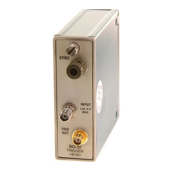
Using the Trigger Head Figure 4 shows the front panel of the SD 51 Trigger Head and identifies the knob and connectors. Lock down Screw Sync Control Input Connector Trigger Out Connector Figure 4: SD 51 Trigger Head Front Panel The SD 51 Trigger Head is controlled entirely from the front panel;... -
Page 23: Signal Connectors
Using the Trigger Head Signal Connectors The INPUT and TRIG OUT signal connectors are precision 3.5 mm connec tors that are mechanically compatible with the SMA standard. Follow pre cautions stated under Connector Care when connecting any cables or adapters. Connecting an Input Connect a 1 GHz to 20 GHz signal that you wish to trigger on to the INPUT connector. -
Page 24: Connecting To Trigger Out
Using the Trigger Head Connecting to Trigger The TRIG OUT connector provides a trigger pulse that can be synchronized with the input signal. The output pulse is typically 200 mV into a 50 W load with a time between pulses of 9 ms to 15 ms, depending on the input signal frequency. -
Page 25: Sync Adjustment
Using the Trigger Head SYNC Adjustment To make the SYNC adjustment, perform the following steps: Step 1: Connect a 1 to 20 GHz signal to the SD 51 INPUT connector. Step 2: Connect the TRIG OUT signal from the SD 51 Trigger Head to the Trigger Input of the instrument mainframe. -
Page 26: Setup Example
5 attenuator (Tektronix part 015-1002-00) a signal generator, such as the Tektronix SG 504, capable of producing a signal in the 1 GHz to 20 GHz range with 1 V to 50 V amplitude. The power divider and 5 attenuator reduce the signal level at the SD 51 input by ten. - Page 27 Using the Trigger Head CAUTION To prevent damage to the trigger or sampling head and instrument, never install or remove a trigger or sampling head when the main frame power is on. Connect your equipment as shown in Figure 5, then proceed. Step 1: Initialize the instrument (press the UTILITY button and touch Initialize).
-
Page 28: Specifications
Specifications Table 1: Input/Output Electrical Specifications Characteristics Specifications Signal Input Bandwidth 1 to 20 GHz typical Minimum Sensitivity 100 mV into 50 W Maximum (Non destructive) Signal 5.0 V Voltage Termination Impedance 50 W open termination paralleled by 1 pF, typical Kickout Pulse Amplitude 180 mV peak, typical Trigger Output... - Page 29 Specifications SD 51 User Manual Artisan Technology Group - Quality Instrumentation ... Guaranteed | (888) 88-SOURCE | www.artisantg.com...
-
Page 30: Glossary
Glossary Channel A place to connect a signal or attach a network or transmission line to sampling heads. Also, the smallest component of a trace expression. Channel Number The number assigned to a specific signal input connector. The top channel of the left most sampling head compartment of the instrument mainframe is always mainframe channel 1, regardless of any reposition ing or omission of sampling heads. - Page 31 Glossary SD 51 User Manual Artisan Technology Group - Quality Instrumentation ... Guaranteed | (888) 88-SOURCE | www.artisantg.com...
-
Page 32: Index
Index Adjustment, SYNC control, 11 Front panel SELECT CHANNEL button, 16 connectors, 11, 12 Attenuator Setup Example, 15 diagram, 11 5X, 12, 15 Signal connectors, 12 INPUT connector, 12 use of 5X, 12 knob, 11, 12 Signal generator, operation, 16 SYNC control, 11 Storing Countdown head, 5 TRIG OUT, 11... - Page 33 Index Index Artisan Technology Group - Quality Instrumentation ... Guaranteed | (888) 88-SOURCE | www.artisantg.com...
- Page 34 Artisan Technology Group - Quality Instrumentation ... Guaranteed | (888) 88-SOURCE | www.artisantg.com...
- Page 35 Artisan Technology Group - Quality Instrumentation ... Guaranteed | (888) 88-SOURCE | www.artisantg.com...
- Page 36 Artisan Technology Group is your source for quality new and certified-used/pre-owned equipment SERVICE CENTER REPAIRS WE BUY USED EQUIPMENT • FAST SHIPPING AND DELIVERY Experienced engineers and technicians on staff Sell your excess, underutilized, and idle used equipment at our full-service, in-house repair center We also offer credit for buy-backs and trade-ins •...
Need help?
Do you have a question about the SD-51 and is the answer not in the manual?
Questions and answers