Sign In
Upload
Download
Table of Contents
Contents
Add to my manuals
Delete from my manuals
Share
URL of this page:
HTML Link:
Bookmark this page
Add
Manual will be automatically added to "My Manuals"
Print this page
×
Bookmark added
×
Added to my manuals
Manuals
Brands
Tektronix Manuals
Media Converter
SD-22
User manual
Tektronix SD-22 User Manual
Sampling head
Hide thumbs
1
2
3
4
Table Of Contents
5
6
7
8
9
10
11
12
13
14
15
16
17
18
19
20
21
22
23
24
25
26
27
28
29
30
31
32
33
34
35
36
37
38
39
40
41
42
43
44
page
of
44
Go
/
44
Contents
Table of Contents
Bookmarks
Table of Contents
Table of Contents
List of Figures
List of Tables
Introduction
Figure 1: Block Diagram of the Sampling Head
Safety
Electrostatic Discharge
Connector Care
Installing the Sampling Head
Figure 2: Sampling Head Compartments in an 11801B and a
Figure 3: Installing a Sampling Head in an Instrument
Using the Sampling Head
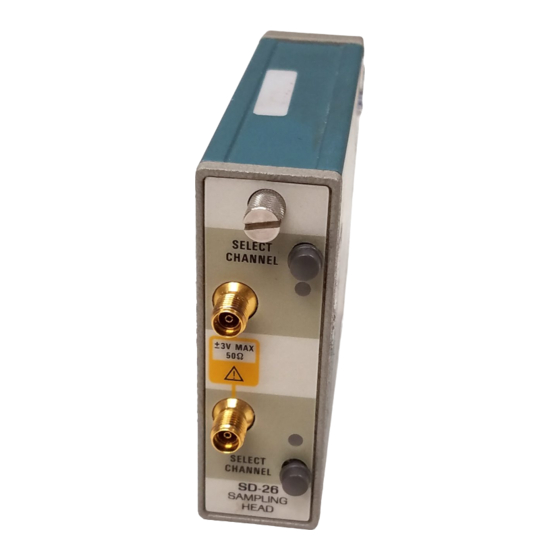
Figure 4: Sampling Head Front Panel
Connecting Signals
Button and Lights
Instrument/Sampling Head Interaction
Smoothing
External Attenuation
Figure 5: the Sampling Head Fnc's Pop up Menu
Displaying a Trace
Figure 6: the Calibrator Signal after Pressing Autoset
Adjusting Parameters
Stored Parameters
Loop Gain
Figure 7: Displayed Trace at Various Loop Gain Settings
Adjusting Loop Gain
Offset Null
Adjusting Offset Null
Specifications
Glossary
Index
Advertisement
Quick Links
Download this manual
®
Advanced Test Equipment Rentals
www.atecorp.com 800-404-ATEC (2832)
User Manual
SD-22 & SD-26
Sampling Head
070–7226–03
Table of
Contents
Previous
Page
Next
Page
1
2
3
4
5
Advertisement
Table of Contents
Need help?
Do you have a question about the SD-22 and is the answer not in the manual?
Ask a question
Questions and answers
Related Manuals for Tektronix SD-22
Media Converter Tektronix SD-44 Instruction Manual
Optical-to-electrical converter (30 pages)
Media Converter Tektronix SD-51 User Manual
Trigger head (36 pages)
Media Converter Tektronix SD-42 User Manual
Optical to electrical converter heads (48 pages)
Media Converter Tektronix SA-42 Instruction Manual
Optical to electrical converter (68 pages)
Media Converter Tektronix SD-48 Instruction Manual
Optical-to-electrical converter (37 pages)
Media Converter Tektronix SD-26 User Manual
Sampling head (44 pages)
Media Converter Tektronix 1503C User Manual
Metallic time-domain reflectometer (128 pages)
Media Converter Tektronix KEITHLEY KUSB-488B Quick Start Manual
Usb to gpib converter (11 pages)
Media Converter Tektronix TVC 501 Service Manual
Time to voltage converter (108 pages)
Media Converter Tektronix MTD200 User Manual
Mpeg test decoder (211 pages)
Media Converter Tektronix P6701B Service Manual
O/econverters (38 pages)
Media Converter Tektronix P6701A Instruction Manual
O/e converters (74 pages)
Media Converter Tektronix P7001 Instruction Manual
Interim (47 pages)
Media Converter Tektronix WVR52003G User Manual
Waveform rasterizer (158 pages)
Media Converter Tektronix 7D12 Service Instructions Manual
A/d converter (100 pages)
Media Converter Tektronix 7D12 Operator's Instruction Manual
A/d converter (37 pages)
This manual is also suitable for:
Sd-26
Table of Contents
Print
Rename the bookmark
Delete bookmark?
Delete from my manuals?
Login
Sign In
OR
Sign in with Facebook
Sign in with Google
Upload manual
Upload from disk
Upload from URL


Need help?
Do you have a question about the SD-22 and is the answer not in the manual?
Questions and answers