Table of Contents
Advertisement
Quick Links
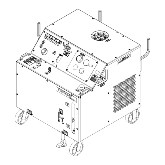
OPERATION & SERVICE MANUAL
54X1 Series
5411, 5421, 5431, 5441
Hydraulic Power Unit
07/2023 − Rev. 06
For Spare Parts, Operations & Service Manuals or Service Needs
Scan the QR code or visit Tronair.com/aftermarket
Tronair, Inc.
Phone: (419) 866-6301 | 800-426-6301
1 Air Cargo Pkwy East
Web: www.tronair.com
Swanton, OH 43558
Email: sales@tronair.com
Advertisement
Table of Contents

Related Manuals for Tronair 5431


Summarization of Contents
1.0 PRODUCT INFORMATION
1.1 DESCRIPTION
Details about the Hydraulic Power Unit model numbers and fluid types.
1.2 MODEL & SERIAL NUMBER
Information on locating the model and serial number on the unit.
1.3 MANUFACTURER
Tronair, Inc. contact information.
1.4 FUNCTION
Explains the purpose and operation of the HPU.
1.5 REQUIREMENTS
Details the electrical power requirements for the HPU.
2.0 SAFETY INFORMATION
2.1 USAGE AND SAFETY INFORMATION
General safety guidelines and warning explanations for HPU operation.
2.2 EXPLANATION OF WARNING & DANGER SIGNS
Explains the meaning of hazard symbols used in the manual.
2.3 COMPONENT SAFETY FEATURES
Lists safety features integrated into the HPU components.
2.4 FUNCTIONAL SAFETY FEATURES
Describes built-in safety features related to HPU functionality.
2.5 PERSONAL PROTECTION EQUIPMENT
Specifies necessary personal protective equipment (PPE) for HPU operation.
2.6 SAFETY GUIDELINES
Provides essential safety rules for operating the HPU.
2.7 GENERAL COMMENTS
General remarks about HPU intended use and manual adherence.
3.0 PREPARATION PRIOR TO FIRST USE
3.1 GENERAL
Initial preparation steps before operating the HPU.
3.2 SERVICING RESERVOIR
Instructions for filling the HPU reservoir with hydraulic fluid.
3.3 CONNECTING ELECTRICAL LEADS
Guidelines for safely connecting electrical power to the HPU.
4.0 TRAINING
4.1 TRAINING REQUIREMENTS
Outlines employer responsibilities for operator training.
4.2 TRAINING PROGRAM
Details the content of the HPU operator training program.
4.3 OPERATOR TRAINING
Specifies the necessary training for safe HPU operation.
5.0 OPERATION
5.1 OPERATING PARAMETERS
Key parameters and requirements for HPU operation.
5.2 NUMERICAL VALUES
Lists numerical specifications for HPU components.
5.2.1 Fluid
Lists the fluid types for different HPU models.
5.2.2 Physical
Provides physical specifications (weight, dimensions) of the HPU.
5.2.3 Motor Driven Hydraulic Pump
Details specifications for the HPU's motor-driven hydraulic pump.
5.2.4 Electric Motor
Information about the HPU's 25 horsepower electric motor.
5.2.5 Filters
Describes the specifications of the various filters used in the HPU.
5.2.6 Hand Pump (Option M)
Specifications for the two-stage hand pump option.
5.3 LOCATION & LAYOUT OF CONTROLS
Identifies and describes controls on the HPU panels.
5.3.1 Front Panel Controls
Identifies and describes controls on the front panel of the HPU.
5.3.2 Electrical Control Panel
Details the functions of the switches, lights, and indicators on the electrical panel.
5.3.3 Hydraulic Control Panel
Explains the gauges and ports on the hydraulic control panel.
5.3.4 Rear Panel Controls
Identifies components and connections on the rear panel of the HPU.
5.3.5 Hydraulic Pump Controls
Describes the flow and pressure controls for the hydraulic pump.
5.3.6 Hand Pump Controls (Option M)
Details the controls and components related to the hand pump option.
5.3.7 Split System Controls (Option C)
Explains the valves and hoses for split system operation.
5.3.8 Split System Crossover Check Controls (Option D)
Describes controls for split system operation with crossover check functionality.
5.3.9 Return Back-Pressure with Sight Gauge (Option T)
Details the components for return back-pressure monitoring.
5.4 START UP PROCEDURES
Procedures for starting the HPU.
5.4.1 Procedure for First Time or Different Electrical Supply ONLY
Steps for initial HPU startup or after electrical supply changes.
5.4.2 Initial Start Up of the HPU
Standard procedures for starting the HPU.
5.5 PRELIMINARY ADJUSTMENTS FOR OPERATION
Adjustments to be made before HPU operation.
5.5.1 Flow Control Adjustment
Steps to adjust the HPU's flow control.
5.5.2 Pressure Control Adjustment
Steps to adjust the HPU's pressure control.
5.5.3 Reservoir Selector Valve Operation
How to operate the reservoir selector valve.
5.5.4 Bypass Valve Operation
Instructions for operating the bypass valve.
5.6 BLEEDING AIR FROM SYSTEM
Procedure for removing air from the hydraulic system.
5.6.1 To Easily Purge the Unit of Air
Procedure for removing air from the hydraulic system.
5.7 SPLIT SYSTEM OPERATION (Option C)
Steps for operating the split system.
5.7.1 To Operate the Split System
Steps for operating the split system.
5.8 SPLIT SYSTEM CROSSOVER CHECK (Option D)
Procedure for operating the split system with crossover check.
5.9 HAND PUMP OPERATION (Option M)
Instructions for using the hand pump.
5.9.1 To Operate the Hand Pump
Instructions for using the hand pump.
5.10 SAMPLE VALVE
Location and purpose of the sample valve.
5.11 EMERGENCY SHUT DOWN PROCEDURE
Steps for emergency shutdown of the HPU.
5.12 DESCRIPTION OF ALARM SYSTEMS
Description of HPU alarm systems and indicators.
5.12.1 High Fluid Temperature Indicator (Option S)
Explanation of the high fluid temperature indicator light.
5.12.2 Voltage/Phase Monitor Indicator (Options G − J)
Details the voltage/phase monitor indicator light.
5.12.3 High and Low Reservoir Level Indicator (Option L)
Description of reservoir level indicator lights.
5.12.4 Clogged Filter Indicator Light (Option R)
Information about the clogged filter indicator light.
5.13 INFREQUENT HPU USE
Guidelines for infrequent use of the HPU.
5.13.1 Infrequent HPU Use Start Up Procedure
Procedure for starting the HPU after periods of inactivity.
6.0 PACKAGING AND STORAGE
6.1 PACKAGING REQUIREMENTS
Guidelines for packaging the HPU.
6.2 HANDLING
Instructions for safely handling and lifting the HPU.
6.3 PACKAGING PROTECTION
Specifies packaging material requirements.
6.4 LABELING OF PACKAGING
Recommended labels for HPU packaging.
6.5 STORAGE COMPATIBILITY
Considerations for storing the HPU.
6.6 STORAGE ENVIRONMENT
Recommendations for the storage environment.
6.7 STORAGE SPACE AND HANDLING FACILITIES
Physical dimensions for storage.
8.0 TROUBLE SHOOTING
8.1 HPU WILL NOT START
Common causes and solutions for HPU startup failures.
8.2 NO FLOW
Troubleshooting steps for when the HPU has no fluid flow.
8.3 REDUCED FLOW
Identifies causes and solutions for reduced fluid flow.
8.4 NO PRESSURE or REDUCED PRESSURE
Troubleshooting steps for pressure-related issues.
8.5 FLUID OVERHEATS
Explains why the HPU fluid might overheat and solutions.
8.6 HAND PUMP (Option M) IS NOT PUMPING FLUID
Solutions for the hand pump not delivering fluid.
9.0 MAINTENANCE
9.1 GENERAL
General maintenance checks and recommendations.
9.2 ELECTRIC MOTOR
Maintenance information for the electric motor.
9.3 MOTOR DRIVEN HYDRAULIC PUMP
Information about the motor-driven hydraulic pump.
9.3.1 Motor Driven Hydraulic Pump Assembly
Lists parts for the hydraulic pump assembly.
9.3.2 Motor Driven Hydraulic Pump Replacement Kits List
Information on replacement kits for the hydraulic pump.
9.4 HYDRAULIC FLUID
Guidance on hydraulic fluid analysis and types.
9.5 FILTERS
Information about the HPU filters.
9.5.1 Pressure Filter
Instructions for replacing the pressure filter element.
9.5.2 Return Filter
Instructions for replacing the return filter element.
9.5.3 Hand Pump (Option M) Filter
Guidance on replacing the hand pump filter element.
9.5.4 Desiccant Air Filter
When and how to replace the desiccant air filter.
9.6 HYDRAULIC HOSES
Information on inspecting and replacing hydraulic hoses.
9.7 INSTRUMENT PANEL
Details of the HPU instrument panels.
9.7.1 Electric Panel
Details the components of the electric control panel.
9.7.2 Hydraulic Panel
Lists and describes components on the hydraulic control panel.
9.7.3 Control Block/Flowmeter
Information on the control block and flowmeter.
9.7.3.a System Pressure Relief Valve
Details on the system pressure relief valve.
9.7.3.b Check Valve
Information about the check valve.
9.7.3.c Bypass Valve
Details on the bypass valve.
9.7.4 Flow Control
Information on the flow control valve.
9.7.5 Pressure Control
Details on the pressure control valve.
9.8 RESERVOIR ASSEMBLY
Information about the reservoir assembly and its components.
9.9 RETURN MANIFOLD ASSEMBLY
Details on the return manifold assembly.
9.9.1 Return System Pressure Relief Valve
Information on the return system pressure relief valve.
9.10 PRESSURE FILTER ASSEMBLY (Single System)
Details the pressure filter assembly.
9.11 ELECTRICAL COMPONENTS
Lists and describes electrical components.
9.11.1 Electrical Components With 100 ft. Input Cord Option
Lists electrical components for units with a 100 ft cord.
9.12 HEAT EXCHANGER ASSEMBLY
Information on the heat exchanger assembly.
9.13 EXTERNAL COMPONENTS
Lists and describes the external components of the HPU.
9.14 ADDITIONAL FEATURES
Details on optional features for the HPU.
9.14.1 50 ft (15.2 m) Hoses (Option B)
Details for the 50 ft hose option.
9.14.2 Split System (Option C)
Information on the split system option.
9.14.3 Crossover Check (Option D)
Details on the crossover check option.
9.14.4 Hour Meter (Options E and F)
Information on the hour meter.
9.14.5 Voltage/Phase Monitor (Options G − J)
Details on the voltage/phase monitor.
9.14.6 Pyrometer (Option K)
Information about the pyrometer.
9.14.7 Electric Reservoir Level (Option L)
Details on the electric reservoir level switch.
9.14.8 Hand Pump (Option M)
Information on the hand pump option.
9.14.9 Hand Pump (Option M-7)
Details on the Hand Pump (Option M-7).
9.14.10 Towing Trailer (Option N)
Information about the towing trailer option.
9.14.11 Calibration Port (Option Q)
Details on the calibration port option.
9.14.12 Electric Filter Clogging Indicator (Option R)
Information on the electric filter clogging indicator.
9.14.13 Electric Over-Temperature (Option S)
Details on the electric over-temperature switch.
9.14.14 Return Back-Pressure with Sight Gauge (Option T)
Information on the return back-pressure option.
9.14.14.a Item 16 Sight Glass Assembly Exploded View
Exploded view of the sight glass assembly.
9.14.15 Return Sight Gauge (Option U)
Details on the return sight gauge option.
9.14.16 Return Back Pressure (Option V)
Information on the return back pressure option.
9.14.17 Drip Pan (Option 4)
Details on the drip pan option.
9.15 REPLACEMENT LABELS PARTS LISTS
Lists of replacement labels for various HPU parts.
9.15.1 Base Unit
Lists replacement labels for the base unit.
9.15.2 Fluid Labels
Lists labels for different fluid types.
9.15.3 Filter Element Kit Labels
Lists labels for filter element kits.
9.15.4 Split System (Option C) and Crossover Check (Option D) Labels
Labels for split system and crossover check options.
9.15.5 Pyrometer (Option K) Label
Label for the pyrometer option.
9.15.6 Hand Pump (Option M) Labels
Labels for the hand pump option.
9.15.7 Calibration Port (Option Q) Labels
Labels for the calibration port option.
9.15.8 Back-Pressure Valve with Sight Glass (Option T) Label
Label for the back-pressure valve with sight glass option.
10.0 PROVISION OF SPARES
10.1 SOURCE OF SPARE PARTS
Information on where to obtain spare parts.
10.2 RECOMMENDED SPARE PARTS LISTS
Lists recommended spare parts for maintenance.
11.0 CALIBRATION OF INSTRUMENTATION
11.1 SOURCE OF CALIBRATION
Information on calibration sources for HPU gauges.
Need help?
Do you have a question about the 5431 and is the answer not in the manual?
Questions and answers