Table of Contents

Subscribe to Our Youtube Channel
Related Manuals for Tronair 5731


Summary of Contents for Tronair 5731
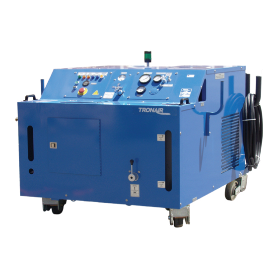
- Page 1 Operation & Service Instructions Model: 5731 Hydraulic Power Unit 08/2016 Rev. 08 Tronair, Inc. 1740 Eber Rd Phone: (419) 866-6301 Holland, OH 43528-9794 www.tronair.com 800-426-6301 Email: sales@tronair.com Fax: (419) 867-0634...
- Page 2 REVISION DATE TEXT AFFECTED 03/2004 Major revision 05/2004 Modified part numbers 06/2006 Modified 9.3.2 Modified 9.7.1 Electric Panel Parts List Modified 9.10 Item 19 06/2008 Modified 12.2.1 Self Calibration 10/2009 Modified 9.10 Electrical Components Added 9.10.1 Electrical Components With 100 ft Input Cord Option 06/2010 Modified illustration for 5.3.5 Hydraulic Pump Controls and 9.2 Electric Motor, modified 9.3.1 Hydraulic Pump Replacement Parts...
-
Page 3: Table Of Contents
Model: 5731 Hydraulic Power Unit TABLE OF CONTENTS PAGE PRODUCT INFORMATION ............................1 DESCRIPTION ................................1 MODEL & SERIAL NUMBER ............................. 1 MANUFACTURER ..............................1 FUNCTION ................................. 1 REQUIREMENTS ..............................1 SAFETY INFORMATION............................... 1 USAGE AND SAFETY INFORMATION ........................1 EXPLANATION OF WARNING &... - Page 4 Model: 5731 Hydraulic Power Unit LABELING OF PACKAGING ........................... 16 STORAGE COMPATIBILITY ........................... 16 STORAGE ENVIRONMENT ............................ 16 STORAGE SPACE AND HANDLING FACILITIES....................16 TRANSPORTATION ..............................16 TROUBLE SHOOTING..............................17 HPU WILL NOT START ............................17 NO FLOW ................................17 REDUCED FLOW ..............................
- Page 5 Model: 5731 Hydraulic Power Unit 12.4 ANALOG TEMPERATURE GAUGE (Pyrometer)..................... 59 12.4.1 Self Calibration ................................. 59 13.0 IN SERVICE SUPPORT .............................. 60 14.0 GUARANTEES/LIMITATION OF LIABILITY ......................60 15.0 APPENDICES ................................60 08/2016 | Rev. 08...
-
Page 6: Product Information
Model: 5731 Hydraulic Power Unit This product can not be modified without the written approval of Tronair, Inc. Any modifications done without written approval voids all warranties and releases Tronair, Inc., it suppliers, distributors, employees, or financial institutions from any liability from consequences that may occur. -
Page 7: Functional Safety Features
Model: 5731 Hydraulic Power Unit SAFETY INFORMATION (continued) FUNCTIONAL SAFETY FEATURES Emergency shut off switch Calibration port shut off valve Floor lock Fluid sample shut off valve PERSONAL PROTECTION EQUIPMENT Safety glasses must be worn when operating the HPU. -
Page 8: Operation
Model: 5731 Hydraulic Power Unit OPERATION OPERATING PARAMETERS The user shall use the HPU in accordance with the aircraft manufacturer's instructions. The user shall operate the HPU in accordance with the Technical and Operator Manuals. The employer of the operator shall provide all necessary training. -
Page 9: Electric Motor
Model: 5731 Hydraulic Power Unit NUMERICAL VALUES (continued) 5.2.4 Electric Motor A 75 horsepower, TEFC electric motor is the prime mover for the HPU. This is attached to the hydraulic pump using a pump/motor adapter and a spider/coupling rotating interface. -
Page 10: Location & Layout Of Controls
Model: 5731 Hydraulic Power Unit OPERATION (continued) LOCATION & LAYOUT OF CONTROLS 5.3.1 Front Panel Controls FIGURE 5.3.1 Front Panel Controls Electrical Control Panel ......See Section 5.3.2 Hydraulic Control Panel ......See Section 5.3.3 Bypass Valve ......... For loading and unloading the Hydraulic Pump. -
Page 11: Electrical Control Panel
Model: 5731 Hydraulic Power Unit LOCATION & LAYOUT OF CONTROLS (continued) 5.3.2 Electrical Control Panel FIGURE 5.3.2 Electrical Control Panel Emergency Stop ........Removes power to all electrical devices, must turn to reset. Stop Switch ..........Turns off the electric motors driving the hydraulic pump and cooling fan. -
Page 12: Hydraulic Control Panel
Model: 5731 Hydraulic Power Unit LOCATION & LAYOUT OF CONTROLS (continued) 5.3.3 Hydraulic Control Panel FIGURE 5.3.3 Hydraulic Control Panel System Pressure Gauge ......Displays the system pressure on an analog fluid dampened gauge. Pyrometer ..........Displays the fluid temperature in the return system on an analog gauge. A warning indicator preset to 160... -
Page 13: Rear Panel Controls
Model: 5731 Hydraulic Power Unit LOCATION & LAYOUT OF CONTROLS (continued) 5.3.4 Rear Panel Controls FIGURE 5.3.4 Rear Panel Controls * Fluid Pressure System ......The source of pressurized fluid from the HPU that flows to the aircraft pressure system through the pressure hose. -
Page 14: Hydraulic Pump Controls
Model: 5731 Hydraulic Power Unit LOCATION & LAYOUT OF CONTROLS (continued) 5.3.5 Hydraulic Pump Controls The hydraulic pump flow control and pressure control are located through the pump control access door. FIGURE 5.3.5 Hydraulic Pump Controls Flow Control ........... This control is used to set the maximum flow required from the HPU. -
Page 15: Hand Pump Controls (Option M)
Model: 5731 Hydraulic Power Unit LOCATION & LAYOUT OF CONTROLS (continued) 5.3.6 Hand Pump Controls (Option M) Reference 5.8 Hand Pump Operation FIGURE 5.3.6 Hand Pump Controls Pump Handle ......... Located inside the front access door is the hand pump handle used for opening and closing the hand pump relief screw and stroking the hand pump arm. -
Page 16: Dual System Controls (Option C)
Model: 5731 Hydraulic Power Unit LOCATION & LAYOUT OF CONTROLS (continued) 5.3.7 Dual System Controls (Option C) Reference 5.7 Dual System Operation. FIGURE 5.3.7 Dual System Controls Pressure Manifold ........Houses the pressure valves. Fluid Pressure Ball Valve ....... Used to turn on and off the flow to separate aircraft systems. Always use in either fully open or fully closed position;... -
Page 17: Start Up Procedures
Model: 5731 Hydraulic Power Unit OPERATION (continued) START UP PROCEDURES 5.4.1 Procedure for First Time or Different Electrical Supply ONLY Phase Monitor (Options H J Only): Check that the phase monitor light on the instrument panel is not illuminated. If the light is illuminated, change any two of the three input leads at the plug. -
Page 18: Pressure Control Adjustment
Model: 5731 Hydraulic Power Unit PRELIMINARY ADJUSTMENTS FOR OPERATION (continued) 5.5.2 Pressure Control Adjustment Open bypass valve. Select "Hydraulic Power Unit" position with reservoir selector valve. Start HPU. Close bypass valve. Adjust pressure control for desired pressure; observing the system pressure gauge, read in psi (bars). Be sure the control shaft lock nut is loose during adjustment. -
Page 19: Bleeding Air From System
Model: 5731 Hydraulic Power Unit OPERATION (continued) BLEEDING AIR FROM SYSTEM Rapid fluctuations of the pressure gage and flow-meter are indications of cavitation or entrapped air in the hydraulic lines and/or components. Air may enter the system when: Operating the unit with insufficient oil in the reservoir. -
Page 20: Sample Valve
Model: 5731 Hydraulic Power Unit OPERATION (continued) SAMPLE VALVE A sample valve is provided on the rear of the unit to obtain a fluid sample for analysis or inspection. In order to obtain a representative fluid sample, it is suggested that ANSI/B93.19M-1972 (R1993) be followed. Reference Appendix VIII. -
Page 21: Packaging And Storage
Model: 5731 Hydraulic Power Unit PACKAGING AND STORAGE PACKAGING REQUIREMENTS Drain hydraulic fluid until level is below the minimum fluid level indicator. Block up the unit on a pallet so the wheels are not touching the pallet or shipping container. -
Page 22: Trouble Shooting
Model: 5731 Hydraulic Power Unit TROUBLE SHOOTING The following is a guide to solutions of common problems associated with the HPU. See related Appendices for Hydraulic and Electrical Schematics. If the problem is not resolved using the trouble shooting information, call the manufacturer for Technical Assistance (See Section 1.3 Manufacturer). -
Page 23: Reduced Flow
Model: 5731 Hydraulic Power Unit TROUBLE SHOOTING (continued) REDUCED FLOW Possible Cause Solution Flow control is set too low ........... Increase flow setting. Pressure adjustment is set too low........Slightly increase pressure setting. Pressure compensator control is ......... When system pressure exceeds the compensator control setting, or... -
Page 24: Maintenance
Model: 5731 Hydraulic Power Unit MAINTENANCE GENERAL Periodically inspect the HPU for loose fasteners, hose fittings, damaged hoses, and worn electrical cables. Make repairs as needed for safe operation. Reference Sections 9.2 9.14 for Parts Lists, Descriptions and Illustrations. -
Page 25: Hydraulic Pump
Model: 5731 Hydraulic Power Unit MAINTENANCE (continued) HYDRAULIC PUMP The hydraulic pump does not require regular maintenance. Under normal operating conditions, the pump will perform for thousands of hours of use without rebuilding. See Appendix Oilgear Pump Manual for further details. -
Page 26: Hydraulic Fluid
(See Section 5.9 Sample Valve Operation) Refer to the manufacturer of the specific fluid for your unit to obtain additional information: Model Number: 5731 Fluid Type: Aviation Phosphate Ester, Type IV 9.5 FILTERS FIGURE 9.5 ... -
Page 27: Pressure Filter Element
Model: 5731 Hydraulic Power Unit FILTERS (continued) 9.5.1 Pressure Filter Element Replace the filter element any time the clogged filter indicator light is triggered. Replace the filter element annually to ensure proper cleanliness of the hydraulic system. This is a minimum requirement. -
Page 28: Return Filter Element
Model: 5731 Hydraulic Power Unit FILTERS (continued) 9.5.2 Return Filter Element Replace the return filter element at the same time the pressure filter element is being replaced. FIGURE 9.5.2 Return Filter Element Replacement PARTS LIST Fluid Type: Aviation Phosphate Ester, Type IV... -
Page 29: Hand Pump (Option M) Filter Element
Model: 5731 Hydraulic Power Unit FILTERS (continued) 9.5.3 Hand Pump (Option M) Filter Element Replacement of the hand pump filter element is dictated by frequency of use and the cleanliness of the fluid, along with the environment to which the HPU is exposed. Changing the hand pump filter element at the same time as the pressure filter element will ensure a regular maintenance schedule. -
Page 30: Desiccant Air Filter
Model: 5731 Hydraulic Power Unit FILTERS (continued) 9.5.4 Desiccant Air Filter Replace the desiccant/air filter whenever the material inside the element is pink or reddish in color (see Element Label for details). FIGURE 9.5.4 Desiccant Air Filter Replacement PARTS LIST... -
Page 31: Pressure Filter Assembly With Electric Filter Clogging Indicator
Model: 5731 Hydraulic Power Unit FILTERS (continued) 9.5.5 Pressure Filter Assembly with Electric Filter Clogging Indicator The Electric Filter Clogging Indicator does not require regular general maintenance. The panel light will illuminate when the clogging indicator senses a 98 psi differential pressure across the filter element. Installing a new filter element will eliminate the clogged condition. -
Page 32: Return Filter Assembly
Model: 5731 Hydraulic Power Unit FILTERS (continued) 9.5.6 Return Filter Assembly FIGURE 9.5.6 Return Filter Assembly PARTS LIST Fluid Type: Aviation Phosphate Ester, Type IV Item Part Number Description 1 ......N-2036-13-S-E ........ Fitting, 37 Swivel ..............1 2 ......HC-2045-02 ........Filter, Return ................1 3 ...... -
Page 33: Hydraulic Hoses
Model: 5731 Hydraulic Power Unit MAINTENANCE (continued) HYDRAULIC HOSES Hoses used on the HPU must be periodically inspected for damage, blisters, leaks, or hose end problems. Any damaged or defective hose should be replaced as soon as possible. Hoses used on Aviation Phosphate Ester, Type IV units have a shorter useful life than hoses used on Mineral Base units. -
Page 34: Instrument Panel
Model: 5731 Hydraulic Power Unit MAINTENANCE (continued) INSTRUMENT PANEL Refer to Section 9.6 Hydraulic Hoses concerning hose inspection for general maintenance on Item 3 Hose Assembly. FIGURE 9.7 Instrument Panel PARTS LIST Fluid Type: Aviation Phosphate Ester, Type IV... -
Page 35: Electric Panel
Model: 5731 Hydraulic Power Unit INSTRUMENT PANEL (continued) 9.7.1 Electric Panel The Electric Panel does not require regular general maintenance. FIGURE 9.7.1 Electric Panel PARTS LIST Fluid Type: Aviation Phosphate Ester, Type IV Item Component Part Number Description 1 ....Standard ......EC-1945-01 ......Light, Diffused Pilot ..........1 2 ....Standard ...... -
Page 36: Hydraulic Panel
Model: 5731 Hydraulic Power Unit INSTRUMENT PANEL (continued) 9.7.2 Hydraulic Panel Annual calibration of instrumentation is recommended. See Section 12.0 Calibration of Instrumentation for details of calibration. FIGURE 9.7.2 Hydraulic Panel PARTS LIST Fluid Type: Aviation Phosphate Ester, Type IV... -
Page 37: Pressure Manifold Assembly
Model: 5731 Hydraulic Power Unit INSTRUMENT PANEL (continued) 9.7.3 Pressure Manifold Assembly The Pressure Manifold components do not require regular general maintenance. FIGURE 9.7.3 Pressure Manifold Assembly PARTS LIST Fluid Type: Aviation Phosphate Ester, Type IV Item Part Number Description 1 ...... -
Page 38: System Pressure Relief Valve
Model: 5731 Hydraulic Power Unit 9.7.3 Pressure Manifold Assembly (continued) 9.7.3.a System Pressure Relief Valve The System Pressure Relief Valve does not require regular general maintenance. It is possible however, for a contaminant to hold the relief valve in a partially open condition. If service is required, the new or repaired relief valve must be reset to 3,750 psig. -
Page 39: Check Valve
Model: 5731 Hydraulic Power Unit 9.7.3 Pressure Manifold Assembly (continued) 9.7.3.b Check Valve The Check Valve does not require regular general maintenance. FIGURE 9.7.3.b Check Valve PARTS LIST Fluid Type: Aviation Phosphate Ester, Type IV Item Part Number Description ... -
Page 40: Reservoir Assembly
Model: 5731 Hydraulic Power Unit MAINTENANCE (continued) RESERVOIR ASSEMBLY Replace the desiccant air filter whenever the material inside the element is pink or reddish in color (See Element label for details). The Reservoir Assembly does not require regular general maintenance. If periodic inspections for silt are desired, be certain to thoroughly clean the dome cover and surrounding area before removing the dome cover. - Page 41 Model: 5731 Hydraulic Power Unit RESERVOIR ASSEMBLY (continued) PARTS LIST Fluid Type: Aviation Phosphate Ester, Type IV Item Part Number Description 1 ......N-2206-09-S ........Plug, Hex Head, 2" NPT ............1 2 ......G-1202-1100 ........Stopnut, Elastic 5/8-11 ............. 2 3 ......
-
Page 42: Return Manifold Assembly
Model: 5731 Hydraulic Power Unit MAINTENANCE (continued) RETURN MANIFOLD ASSEMBLY The Return Manifold does not require regular general maintenance. NOTE: DO NOT attempt to adjust the Return System Pressure Relief Valve. See Section 9.9.1 Return System Pressure Relief Valve for details. -
Page 43: Return System Pressure Relief Valve
Model: 5731 Hydraulic Power Unit RETURN MANIFOLD ASSEMBLY (continued) 9.9.1 Return System Pressure Relief Valve The Return System Pressure Relief Valve can be purchased as a preset assembly. If the relief valve is serviced by the end user, the valve must be set to crack at 150+/-7 psig before being re-installed on the HPU. -
Page 44: Electrical Components
Model: 5731 Hydraulic Power Unit MAINTENANCE (continued) 9.10 ELECTRICAL COMPONENTS Regularly inspect the external power cord for nicks, cuts, abrasion, and fluid damage. Replace power cord if damage is found. See Section 10.0 Provision of Spares for recommended spare fuses. - Page 45 Model: 5731 Hydraulic Power Unit 9.10 ELECTRICAL COMPONENTS (continued) PARTS LIST Fluid Type: Aviation Phosphate Ester, Type IV Item Part Number Description 28 ......EC-1597 .......... Rail, Din ..................1 29 ......G-1202-1070 ........Stopnut, Elastic 3/8 – 16 ............6 30 ......
-
Page 46: Electrical Components With 100 Ft Input Cord Option
Model: 5731 Hydraulic Power Unit 9.10 ELECTRICAL COMPONENTS (continued) 9.10.1 Electrical Components With 100 ft Input Cord option Regularly inspect the external power cord for nicks, cuts, abrasion, and fluid damage. Replace power cord if damage is found. See Section 10.0 Provision of Spares for recommended spare fuses. - Page 47 Model: 5731 Hydraulic Power Unit 9.10.1 Electrical Components With 100 ft. Input Cord Option (continued) PARTS LIST 60 Hz Applications Item Description EC-1598 EC-1598 EC-1598 Rail, Din G-1159-103504 G-1159-103504 G-1159-103504 Screw, RD HD CRS REC, #10-32 x ½ Long G-1250-1030N...
- Page 48 Model: 5731 Hydraulic Power Unit 9.10.1 Electrical Components With 100 ft. Input Cord Option (continued) PARTS LIST 50 Hz Applications Item Description EC-1598 EC-1598 EC-1598 Rail, Din G-1159-103504 G-1159-103504 G-1159-103504 Screw, RD HD CRS REC, #10-32 x ½ Long G-1250-1030N...
-
Page 49: Heat Exchanger Assembly
Model: 5731 Hydraulic Power Unit MAINTENANCE (continued) 9.11 HEAT EXCHANGER ASSEMBLY The Heat Exchanger Assembly does not require regular general maintenance. FIGURE 9.11 Heat Exchanger Assembly PARTS LIST Fluid Type: Aviation Phosphate Ester, Type IV Item Part Number Description 1 ...... -
Page 50: External Components
Model: 5731 Hydraulic Power Unit MAINTENANCE (continued) 9.12 EXTERNAL COMPONENTS Keep HPU clean. Do not allow labels to become damaged; thusly illegible. Regularly inspect casters and floor locks to ensure safe working condition. FIGURE 9.12 External Components PARTS LIST... -
Page 51: Additional Features
Model: 5731 Hydraulic Power Unit MAINTENANCE (continued) 9.13 ADDITIONAL FEATURES 9.13.1 50 ft (15.2 m) Hoses (Option B) Refer to Section 9.6 Hydraulic Hoses concerning hose inspection. PARTS LIST Fluid Type: Aviation Phosphate Ester, Type IV Part Number Description TF-1040-05*300 ........Pressure Hose, 25 ft/7.6 m ........... 1 per Option TF-1041-04*300 ........ -
Page 52: Voltage/Phase Monitor (Options H J)
Model: 5731 Hydraulic Power Unit 9.13 ADDITIONAL FEATURES (continued) 9.13.3 Voltage/Phase Monitor (Options H The Voltage/Phase Monitor does not require regular general maintenance. The panel indicator light will illuminate if a tripped condition exists. If the Voltage/Phase Monitor is causing the HPU to shut off, verify the Phase Monitor settings shown. -
Page 53: Electric Reservoir Level (Option L)
Model: 5731 Hydraulic Power Unit 9.13 ADDITIONAL FEATURES (continued) 9.13.4 Electric Reservoir Level (Option L) The Electric Reservoir Level switch does not require regular general maintenance. Panel indicator lights will indicate low or high fluid level. NOTE: Wire per Electrical Schematic INS-1608. Reference Wiring Diagram INS-1597. Reference 9.7.1 Electrical Panel for Panel Light. -
Page 54: Hand Pump (Option M)
Model: 5731 Hydraulic Power Unit 9.13 ADDITIONAL FEATURES (continued) 9.13.5 Hand Pump (Option M) Refer to Section 9.6 Hydraulic Hoses concerning hose inspection for general maintenance on Items 4, 5, 7 and 13 hose assemblies. Refer to Section 9.5.3 Hand Pump (Optional) Filter . - Page 55 Model: 5731 Hydraulic Power Unit This page left blank intentionally 08/2016 | Rev. 08 Page | 50...
-
Page 56: Two Stage Pump With Relief
Model: 5731 Hydraulic Power Unit 9.13.5 Hand Pump (Option M) (continued) 9.13.5.a Two Stage Pump with Relief FIGURE 9.13.5.a Two Stage Pump with Relief 08/2016 | Rev. 08 Page | 51... - Page 57 Model: 5731 Hydraulic Power Unit 9.13.5.a Two Stage Pump with Relief (continued) PARTS LIST Fluid Type: Aviation Phosphate Ester, Type IV Item Part Number Description 1 ......519-000 ........... Pin .................... 1 3 ......CXC-990022-001 ......Body ..................1 7 ......505-001 ........... Plug, Valve Body ..............3 15 ......
-
Page 58: Hand Pump High Displacement (Option 7)
Model: 5731 Hydraulic Power Unit 9.13 ADDITIONAL FEATURES (continued) 9.13.6 Hand Pump High Displacement (Option 7) Refer to Section 9.6 Hydraulic Hoses concerning hose inspection for general maintenance on Items 3, 4, 11, 18 and 23 hose assemblies. Refer to Section 9.5.3 Hand Pump (Optional) Filter . - Page 59 Model: 5731 Hydraulic Power Unit 9.13.6 Hand Pump High Displacement (Option 7) (continued) Parts List Fluid Type: Aviation Phosphate Ester, Type IV and V Item Part Number Description N-2016-06-S HC-2724 PUMP, HYDRAULIC TF-1041-09-26 ASSEMBLY, HOSE #8 TF-1041-66-56.5 ASSEMBLY, HOSE #6...
-
Page 60: Towing Trailer (Option N)
Model: 5731 Hydraulic Power Unit 9.13 ADDITIONAL FEATURES (continued) 9.13.7 Towing Trailer (Option N) Capacity: 4,000 lbs (1,814 kg) Front Axle Capacity: 2,000 lbs (907 kg) Rear Axle Capacity: 2,000 lbs (907 kg) Tires: 4.80-8NHS x 6 Ply Rated at 970 lbs (440 kg) (105 psi at 10 mph/7.24 bar at 16 kph) FIGURE 9.13.6 ... -
Page 61: Replacement Labels Parts Lists
9.14.1 Base Unit Part Number Description V-1001 .............."Made in USA" ....................1 V-1033-01 ............."TRONAIR" ....................1 V-1050 ..............ISO Electrical Shock Symbol ................. 2 V-1365 .............."SYSTEM PRESSURE" ................. 1 V-1366 .............."HPU BY-PASS VALVE" ................1 V-1374 .............."ROTATION"....................1 V-1470 .............."CAUTION . . ." ....................1 V-1882 ..............Control Panel Lights .................. -
Page 62: Provision Of Spares
K-3616 ..............Kit, Return Filter Element ................1 * ................Kit, Shaft Seal and Retainer for Main Pump ..........1 K-3752 ..............Kit, Hand Pump Filter Element (Optional) ............1 * Not available at time of publishing. Call Tronair for Part Number. 11.0 ELECTRICAL POWER REQUIREMENTS The electrical power supply for the HPU must include a fused disconnect using Type J or Type R fuses or equivalent magnetic type circuit breakers designed for protecting an electrical motor. -
Page 63: Calibration Of Instrumentation
CALIBRATION OF INSTRUMENTATION All gauges on the Hydraulic Power Unit can be either returned to Tronair for calibration or certified by the end user if proper calibration equipment is available. Gauges returned to Tronair for calibration will be tested with standards traceable to N.I.S.T. -
Page 64: Analog Pressure Gauge (Hand Pump Pressure- Option M Only )
Model: 5731 Hydraulic Power Unit 12.0 CALIBRATION OF INSTRUMENTATION (continued) 12.3 ANALOG PRESSURE GAUGE (Hand Pump Pressure- Option M Only ) 12.3.1 Self Calibration An accurate pressure calibration gauge is required for calibration of the Hand Pump Pressure gauge. Follow the necessary steps below. - Page 65 GUARANTEES/LIMITATION OF LIABILITY Tronair products are warranted to be free of manufacturing or material defects for a period of one year after shipment to the original customer. This is solely limited to the repair or replacement of defective components. This warranty does not cover the...
- Page 67 APPENDIX I Declaration Conformity...
- Page 69 60204-1:1997 HFPA/JIC T2.24.1-1990 ISO 4021:1997 ARP 1247B NFPA 70/NEC 1999 Identification of person empowered to sign on behalf of the Manufacturer: Quality Assurance Representative Tronair, Inc. 1740 Eber Rd Phone: (419) 866-6301 Holland, OH 43528-9794 www.tronair.com 800-426-6301 Email: sales@tronair.com...
- Page 71 APPENDIX II Hydraulic Schematic (INS-1660)
- Page 73 APPENDIX III Electrical Schematic (INS-1608, INS-2016)
- Page 75 APPENDIX IV Wiring Diagram (INS-1597, INS-2046)
- Page 77 APPENDIX IV Lincoln Motor Manual...
- Page 83 APPENDIX V Oilgear Pump Manual...
- Page 101 APPENDIX VI Material Safety Data Sheet (MSDS) Hydraulic Fluid...
- Page 111 APPENDIX VII ANSI/B93.19M-1972 (R1993-Excerpt)
- Page 117 APPENDIX VIII Instrument Certification Notice...
- Page 119 Re-calibration should be done on a periodic basis as dictated by the end user's quality system or other overriding requirements. Note that Tronair, Inc. does not supply certificates of calibration on flow meters or pyrometers unless requested at the time of placed order. These instruments are considered reference indicators only and are not critical to the test(s) being performed on the aircraft.
Need help?
Do you have a question about the 5731 and is the answer not in the manual?
Questions and answers