Table of Contents
Advertisement
112850S0000
112850D0000
112860S0000
112860D0000
Tronair, Inc.
1 Air Cargo Pkwy East
Swanton, OH 43558
OPERATION & SERVICE MANUAL
28.5 VDC Ground Power Unit
Models:
112850S0100
112850D0100
112860S0100
112860S0100-A4
112860D0100
112860D0100-A5
06/2013 - Rev. 03
112850S0200
112850D0200
112850D0100AV
112850D0100-A5
112860S0200
112860S0200
112860S0100-A6
112860D0200
112860D0200-A5
Phone: (419) 866-6301 | 800-426-6301
Web: www.tronair.com
Email: sales@tronair.com
Advertisement
Table of Contents

Subscribe to Our Youtube Channel
Related Manuals for Tronair 112850S0000


Summary of Contents for Tronair 112850S0000
- Page 1 OPERATION & SERVICE MANUAL 28.5 VDC Ground Power Unit Models: 112850S0000 112850S0100 112850S0200 112850D0200 112850D0000 112850D0100 112850D0100AV 112850D0100-A5 112860S0000 112860S0100 112860S0200 112860S0200 112860S0100-A4 112860S0100-A6 112860D0000 112860D0100 112860D0200 112860D0100-A5 112860D0200-A5 06/2013 - Rev. 03 Tronair, Inc. Phone: (419) 866-6301 | 800-426-6301 1 Air Cargo Pkwy East Web: www.tronair.com...
- Page 2 REVISION DATE TEXT AFFECTED 01/2009 Original Release 03/2009 06/2013 Modified 5.2.3 Converter Commissioning and 5.3 Switching On...
-
Page 3: Table Of Contents
28.5 VDC Ground Power Unit Models 112850S0000 112850S0100 112850S0200 112850D0000 112850D0100/AV 112850D0100-A5 112850D0200 112860S0000 112860S0100 112860S0100-A4 112860S0100-A6 112860S0200 112860D0000 112860D0100 112860SD100-A5 112860D0200 112860SD200-A5 TABLE OF CONTENTS PAGE INTRODUCTION ................................1 MODEL DISCTIPTIONS ............................1 SAFETY NOTES ................................ 2 TECHNICAL DATA ............................... 3 SYSTEM DESCRIPTION ............................... -
Page 4: Introduction
This manual describes the Tronair 28V Ground Power Unit (GPU). If you follow these instructions you will be able to handle the equipment with confidence and utilize all its facilities. -
Page 5: Safety Notes
28.5 VDC Ground Power Unit Models 112850S0000 112850S0100 112850S0200 112850D0000 112850D0100/AV 112850D0100-A5 112850D0200 112860S0000 112860S0100 112860S0100-A4 112860S0100-A6 112860S0200 112860D0000 112860D0100 112860SD100-A5 112860D0200 112860SD200-A5 SAFETY NOTES The 28V DC GPU is a piece of electrical equipment which carries voltages and currents that are hazardous to personnel. The following advice must therefore be observed at all times: ... -
Page 6: Technical Data
28.5 VDC Ground Power Unit Models 112850S0000 112850S0100 112850S0200 112850D0000 112850D0100/AV 112850D0100-A5 112850D0200 112860S0000 112860S0100 112860S0100-A4 112860S0100-A6 112860S0200 112860D0000 112860D0100 112860SD100-A5 112860D0200 112860SD200-A5 TECHNICAL DATA Length: 42 in (107 cm) Width 31 in (79 cm) Single 33 in (84 cm) Dual... -
Page 7: System Description
28.5 VDC Ground Power Unit Models 112850S0000 112850S0100 112850S0200 112850D0000 112850D0100/AV 112850D0100-A5 112850D0200 112860S0000 112860S0100 112860S0100-A4 112860S0100-A6 112860S0200 112860D0000 112860D0100 112860SD100-A5 112860D0200 112860SD200-A5 SYSTEM DESCRIPTION INTRODUCTION The 28V GPU is manufactured using the latest state-of-the-art technology. The design concept and the selected components utilize the latest trends in power electronics, and represents the best solution for the different problems of Ground Power Supplies. -
Page 8: System Control
28.5 VDC Ground Power Unit Models 112850S0000 112850S0100 112850S0200 112850D0000 112850D0100/AV 112850D0100-A5 112850D0200 112860S0000 112860S0100 112860S0100-A4 112860S0100-A6 112860S0200 112860D0000 112860D0100 112860SD100-A5 112860D0200 112860SD200-A5 SYSTEM DESCRIPTION (continued) SYSTEM CONTROL System control consists of one System Interface Board, a firing board, one Operator Panel. -
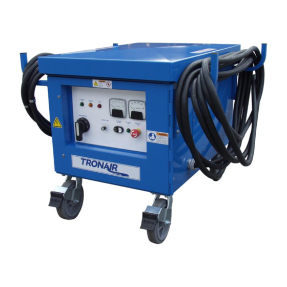
Page 9: Control Panel
28.5 VDC Ground Power Unit Models 112850S0000 112850S0100 112850S0200 112850D0000 112850D0100/AV 112850D0100-A5 112850D0200 112860S0000 112860S0100 112860S0100-A4 112860S0100-A6 112860S0200 112860D0000 112860D0100 112860SD100-A5 112860D0200 112860SD200-A5 SYSTEM DESCRIPTION (continued) CONTROL PANEL There is a local Control Panel on the cubicle door of the converter which contains a light emitting diode (LED) indications, E- Stop, and meters The LED’s on the control panel are red, green and yellow. -
Page 10: Installation And Connections
On completion of any work requiring the opening of the equipment doors or panels or removal of cover plates or gland plates, the unit should be thoroughly vacuumed out and re-packed or protected. Tronair accepts no liability for any damage to equipment caused by physical mal-treatment or by ingress of foreign material. -
Page 11: Space Requirements/Dimensions
Details are shown in the Technical Data (Section 2). The cooling air must always be free of corrosive agents. You should consult your Tronair representative if planning an installation above 1000 meters. ELECTRICAL CONNECTIONS (POWER) 4.5.1... -
Page 12: Cable Sizing
1.5%, and that the connecting cables should be as short as possible especially the output cable (less than 10 m/30 feet is recommended). Tronair should be consulted if these requirements cannot be met. -
Page 13: Operating Instructions
Operator Controls COMMISSIONING WARNING! Before initial start-up, check the following: Is the equipment damaged? If yes, do not put into service without consulting your Tronair representative Is the cabling properly installed? (Mains, output, remote control, etc.,?) Correct if necessary 5.2.1... -
Page 14: Settings
28.5 VDC Ground Power Unit Models 112850S0000 112850S0100 112850S0200 112850D0000 112850D0100/AV 112850D0100-A5 112850D0200 112860S0000 112860S0100 112860S0100-A4 112860S0100-A6 112860S0200 112860D0000 112860D0100 112860SD100-A5 112860D0200 112860SD200-A5 COMMISSIONING (continued) 5.2.2 Settings The rectifier is available in 50 Hz and 60 Hz, both units are capable of being operated at various input voltages. The 50 Hz unit can be operated with 200V, 380V or 415V and the 60Hz unit with 208V, 240V or 480V. - Page 15 28.5 VDC Ground Power Unit Models 112850S0000 112850S0100 112850S0200 112850D0000 112850D0100/AV 112850D0100-A5 112850D0200 112860S0000 112860S0100 112860S0100-A4 112860S0100-A6 112860S0200 112860D0000 112860D0100 112860SD100-A5 112860D0200 112860SD200-A5 5.2.3 Converter Commissioning (continued) Carry out the individual steps in the correct sequence: Check all T-1 transformer connections and tighten if necessary. Ensure voltage is tapped for (480, 240, 208VAC 60Hz or...
-
Page 16: Switching On
28.5 VDC Ground Power Unit Models 112850S0000 112850S0100 112850S0200 112850D0000 112850D0100/AV 112850D0100-A5 112850D0200 112860S0000 112860S0100 112860S0100-A4 112860S0100-A6 112860S0200 112860D0000 112860D0100 112860SD100-A5 112860D0200 112860SD200-A5 5.2.3 Converter Commissioning (continued) 44. Observe amber warning lamp flashes if DC output volts drops below 21 VDC. LET LOAD BANK COOL, push black DC OFF switch 45. -
Page 17: Output Voltage Dc Adjustment
NOTE In the event of a fault, the system fault messages should be evaluated using the chart below. If the cause of the fault is within the converter and you cannot clear it with your own personnel, please contact your Tronair Service representative: TRONAIR, Inc. -
Page 18: Procedures In The Event Of Malfunctions
28.5 VDC Ground Power Unit Models 112850S0000 112850S0100 112850S0200 112850D0000 112850D0100/AV 112850D0100-A5 112850D0200 112860S0000 112860S0100 112860S0100-A4 112860S0100-A6 112860S0200 112860D0000 112860D0100 112860SD100-A5 112860D0200 112860SD200-A5 TROUBLE SHOOTING (continued) PROCEDURES IN THE EVENT OF MALFUNCTIONS Follow the steps below in case of malfunctions:... -
Page 19: Monitors & Fault Indication
MAINTENANCE AND SERVICE PREVENTIVE MAINTENANCE 7.1.1 General Because of their construction, Tronair converters require practically no maintenance. The few operations necessary should be carried out carefully since they contribute to the trouble-free operation and increased service life of the installation. 7.1.2 Cleanliness Always ensure that the system environment is kept as free as possible of dust, metal chips, lubricants, etc. -
Page 20: Additional Information
GUARANTEES/LIMITATION OF LIABILITY Tronair products are warranted to be free of manufacturing or material defects for a period of one year after shipment to the original customer. This is solely limited to the repair or replacement of defective components. This warranty does not cover the... - Page 21 28.5 VDC Ground Power Unit Models 112850S0000 112850S0100 112850S0200 112850D0000 112850D0100/AV 112850D0100-A5 112850D0200 112860S0000 112860S0100 112860S0100-A4 112860S0100-A6 112860S0200 112860D0000 112860D0100 112860SD100-A5 112860D0200 112860SD200-A5 Parts List When ordering replacement parts/kits, please specify model, serial number and color of your unit. Item...
- Page 22 28.5 VDC Ground Power Unit Models 112850S0000 112850S0100 112850S0200 112850D0000 112850D0100/AV 112850D0100-A5 112850D0200 112860S0000 112860S0100 112860S0100-A4 112860S0100-A6 112860S0200 112860D0000 112860D0100 112860SD100-A5 112860D0200 112860SD200-A5 Parts List When ordering replacement parts/kits, please specify model, serial number and color of your unit. Item...
- Page 23 28.5 VDC Ground Power Unit Models 112850S0000 112850S0100 112850S0200 112850D0000 112850D0100/AV 112850D0100-A5 112850D0200 112860S0000 112860S0100 112860S0100-A4 112860S0100-A6 112860S0200 112860D0000 112860D0100 112860SD100-A5 112860D0200 112860SD200-A5 This page left blank intentionally. 06/2013 | Rev. 03 Page | 20...
- Page 24 28.5 VDC Ground Power Unit Models 112850S0000 112850S0100 112850S0200 112850D0000 112850D0100/AV 112850D0100-A5 112850D0200 112860S0000 112860S0100 112860S0100-A4 112860S0100-A6 112860S0200 112860D0000 112860D0100 112860SD100-A5 112860D0200 112860SD200-A5 Parts List When ordering replacement parts/kits, please specify model, serial number and color of your unit. Item...
- Page 25 28.5 VDC Ground Power Unit Models 112850S0000 112850S0100 112850S0200 112850D0000 112850D0100/AV 112850D0100-A5 112850D0200 112860S0000 112860S0100 112860S0100-A4 112860S0100-A6 112860S0200 112860D0000 112860D0100 112860SD100-A5 112860D0200 112860SD200-A5 Parts List When ordering replacement parts/kits, please specify model, serial number and color of your unit. Item...
- Page 26 28.5 VDC Ground Power Unit Models 112850S0000 112850S0100 112850S0200 112850D0000 112850D0100/AV 112850D0100-A5 112850D0200 112860S0000 112860S0100 112860S0100-A4 112860S0100-A6 112860S0200 112860D0000 112860D0100 112860SD100-A5 112860D0200 112860SD200-A5 Parts List When ordering replacement parts/kits, please specify model, serial number and color of your unit. Item...
- Page 27 APPENDIX I Wiring Diagram and Schedule Single Output...
- Page 29 INSTRUCTION DOCUMENT NUMBER: PAGE 1 OF 4 INS-1993 Model: 1128X0S0X00– Wiring Schedule (Single Output 50/60 Hertz)) DATE: 01/2011 REV: 04 NOTE: REFER TO WIRING DIAGRAM INS-2007 WIRE WIRE LETTER SIZE/COLOR FROM 20/BLACK P-6 HARNESS CONNECTOR (PIN 5) EMERGENCY STOP SWITCH SW1 TERMINAL (3) 20/BLACK P-6 HARNESS CONNECTOR (PIN 6) EMERGENCY STOP SWITCH SW2 TERMINAL (1)
- Page 30 INS-1993 1128X0S0X00 WIRING SCHEDULE WIRE WIRE LETTER SIZE/COLOR FROM DC CONTACTOR CONT1 CONTACT 4/0 BLACK P-8 HARNESS CONNECTOR (PIN 1) P-5 HARNESS CONNECTOR (PIN 1) 20/RED 20/RED P-8 HARNESS CONNECTOR (PIN 3) P-5 HARNESS CONNECTOR (PIN 3) 20/RED P-8 HARNESS CONNECTOR (PIN 5) P-5 HARNESS CONNECTOR (PIN 5) 20/RED P-9 HARNESS CONNECTOR (PIN 1)
- Page 31 INS-1993 1128X0S0X00 WIRING SCHEDULE WIRE WIRE LETTER SIZE/COLOR FROM CIRCUIT BREAKER CB5 P-2 HARNESS CONNECTOR (PIN 7) 20/RED TRANSFORMER T3 (RED WIRE) P-2 HARNESS CONNECTOR (PIN 14) 20/GREEN 20/RED P-2 HARNESS CONNECTOR (PIN 3) TRANSFORMER T1 TERMINAL (X3) 4/0 BLACK SCR MODULE MOD1 TERMINAL SCR# 5 20/RED P-2 HARNESS CONNECTOR (PIN 2)
- Page 32 INS-1993 1128X0S0X00 WIRING SCHEDULE WIRE WIRE LETTER SIZE/COLOR FROM BLEED RESISTOR R1 BLEED RESISTOR SOLENOID SOL1 MAIN CONTACT 6/BLACK TRANSFORMER T1 TERMINAL (A3) CIRCUIT BREAKER CB6 12/RED 01/2011 | Rev. 04 Page | 4...
- Page 33 REVISION DATE ORIGINAL RELEASE 16400 08-15-08 UPDATED T4 16995 05-13-09 TRANSFORMER REMOVED T4 17566 05/21/2010 TRANSFORMER ADDED 10 OHM RESISTOR TO SHUNT TRIP CIRCUIT PAN1 Z-6902 FRONT CONTROL PANEL EMERGENCY STOP INPUT POWER ON WARNING FAULT CURRENT LIMIT DC CURRENT DC VOLTS DC CABLE 1 ON/OFF METER...
- Page 34 REVISION DATE EC-2139 FAN1 ORIGINAL RELEASE 16400 08-15-08 UPDATED T4 UNIT FAN 16995 05-13-09 TRANSFORMER [BC] J15 J16 REMOVED T4 17566 05/21/2010 EC-1227-02*0636 TRANSFORMER [AY] INPUT CABLE [BD] ADDED 10 OHM RESISTOR TO SHUNT TRIP CIRCUIT 25uF EC-2141 [BB] 1-Y12 28 VDC SENSE EC2169 CAPACITOR...
- Page 35 REVISION DATE ORIGINAL RELEASE 16400 08-15-08 UPDATED T4 16995 05-13-09 TRANSFORMER REMOVED T4 17566 05/21/2010 TRANSFORMER ADDED 10 OHM RESISTOR TO SHUNT TRIP CIRCUIT =TERMINAL NUMBERS = PLUG JUNCTION =WIRE NAME = N/O RELAY CONTACT = N/C RELAY CONTACT =TERMINAL BLOCK =CHASSIS GROUND EC-1124*240 PAGE NUMBER...
- Page 37 REVISION DATE ORIGINAL RELEASE 16400 08-15-08 CHANGED WIRING 16810 02-05-09 UPDATED GFCI OUTLET 16995 05-13-09 CHANGED “RR” WIRE 17566 05-24-10 ADDED 10 OHM RESISTOR 18613 04-17-12 TO SHUNT TRIP CIRCUIT PAN1 Z-6902 FRONT CONTROL PANEL EMERGENCY STOP INPUT POWER ON WARNING FAULT CURRENT LIMIT...
- Page 38 REVISION DATE EC-2139 FAN1 ORIGINAL RELEASE 16400 08-15-08 CHANGED WIRING 16810 02-05-09 UNIT FAN UPDATED GFCI OUTLET 16995 05-13-09 [BC] CHANGED “RR” WIRE 17566 05-24-10 J15 J16 ADDED 10 OHM RESISTOR EC-1227-02*0636 [AY] 18613 04-17-12 TO SHUNT TRIP CIRCUIT INPUT CABLE [BD] [BB] 1-Y12...
- Page 39 REVISION DATE ORIGINAL RELEASE 16400 08-15-08 CHANGED WIRING 16810 02-05-09 UPDATED GFCI OUTLET 16995 05-13-09 CHANGED “RR” WIRE 17566 05-24-10 ADDED 10 OHM RESISTOR 18613 04-17-12 TO SHUNT TRIP CIRCUIT =TERMINAL NUMBERS = PLUG JUNCTION =WIRE NAME = N/O RELAY CONTACT = N/C RELAY CONTACT =TERMINAL BLOCK =CHASSIS GROUND...
- Page 41 APPENDIX II Wiring Diagram and Schedule Dual Output...
- Page 43 INSTRUCTION DOCUMENT NUMBER: PAGE 1 OF 4 INS-1998 Model: 1128X0D0XXX– Wiring Schedule (Dual Output 50/60 Hertz) DATE: 01/2011 REV: 03 NOTE: REFER TO WIRING DIAGRAM INS-1992 WIRE WIRE LETTER SIZE/COLOR FROM 20/BLACK P-6 HARNESS CONNECTOR (PIN 5) EMERGENCY STOP SWITCH SW1 TERMINAL (3) P-6 HARNESS CONNECTOR (PIN 6) EMERGENCY STOP SWITCH SW2 TERMINAL (1) 20/BLACK...
- Page 44 INS-1998 1128X0D0XXX WIRING SCHEDULE WIRE WIRE LETTER SIZE/COLOR FROM 20/GREEN P-3 HARNESS CONNECTOR (PIN 8) DC SHUNT (PLUS) 20/GREEN P-3 HARNESS CONNECTOR (PIN 4) DC SHUNT (MINUS) 20/BLACK SCR BUS BAR (PLUS) P-3 HARNESS CONNECTOR (PIN 3) 20/RED P-8 HARNESS CONNECTOR (PIN 1) P-5 HARNESS CONNECTOR (PIN 1) 20/RED P-8 HARNESS CONNECTOR (PIN 3)
- Page 45 INS-1998 1128X0D0XXX WIRING SCHEDULE WIRE WIRE LETTER SIZE/COLOR FROM CAPACITOR ASSEMBLY BUS BAR (PLUS) 6/BLACK SCR BUS BAR (PLUS) BLEED RESISTOR R1 CAPACITOR ASSEMBLY BUS BAR (MINUS) 6/BLACK SCR BUS BAR (MINUS) BLEED RESISTOR SOLENOID SOL1 (CONTACT) 20/GREEN TRANSFORMER THERMO TERMINAL BLOCK P-2 HARNESS CONNECTOR (PIN 8) 20/GREEN TRANSFORMER THERMO TERMINAL BLOCK...
- Page 46 INS-1998 1128X0D0XXX WIRING SCHEDULE WIRE WIRE LETTER SIZE/COLOR FROM DC 2 ON LAMP L6 TERMINAL (PLUS) 20/BLACK DC CABLE 2 ON SWITCH SW8 TERMINAL (3) LATCH RELAY 2 K2 TERMINALS (8 & 13) DC 2 ON LAMP L6 TERMINAL (MINUS) 20/GREEN DC 2 POWER OFF SWITCH SW9 TERMINAL (2) LATCH RELAY 2 K2 TERMINAL (14)
- Page 47 REVISION DATE ORIGINAL RELEASE 16810 02/05/09 UDATED T4 16995 05/13/09 TRANSFORMER UDATED T1 17566 05/19/10 TRANSFORMER ADD 10 OHM RESISTOR 18613 05/17/12 FOR SHUNT TRIP CIRCUIT PAN1 Z-6902 DC 1 ON [BE] [BF] [AV] [BL] [BL] [AX] [AV] [AX] DC 2 ON DC CABLE 1 ON/OFF DC CABLE 2 ON/OFF [BE]...
- Page 48 REVISION DATE EC-2139 FAN1 ORIGINAL RELEASE 16810 02/05/09 UDATED T4 UNIT FAN 16995 05/13/09 TRANSFORMER [BC] UDATED T1 J15 J16 FAN COLORS: 17566 05/19/10 TRANSFORMER EC-1227-02*XXXX [AY] BLUE ADD 10 OHM RESISTOR INPUT CABLE [BD] 18613 05/17/12 BROWN FOR SHUNT TRIP CIRCUIT BLACK BLACK 25uF...
- Page 49 CAB1 EC-1124*240 REVISION DATE ORIGINAL RELEASE 16810 02/05/09 UDATED T4 16995 05/13/09 TRANSFORMER UDATED T1 EC-1027 CONT1 17566 05/19/10 TRANSFORMER DC PLUG 1 ADD 10 OHM RESISTOR [BR] ACFT END 2-Z10 [BR] 18613 05/17/12 DC CABLE 1 VOLTS PLUS DC CABLE PLUS FOR SHUNT TRIP CIRCUIT 13064 DC CABLE MINUS...
- Page 51 REVISION DATE ORIGINAL RELEASE 16400 08-15-08 CHANGED WIRING 16810 02-05-09 CHANGED WIRING 16995 05-13-09 CHANGED WIRING 17566 05-19-10 ADDED 10 OHM RESISTOR 18613 05-17-12 TO SHUNT TRIP CIRCUIT PAN1 Z-6902 DC 1 ON [BE] [BF] [AV] [BL] [BL] [AX] [AV] [AX] DC 2 ON DC CABLE 1 ON/OFF...
- Page 52 REVISION DATE EC-2139 FAN1 ORIGINAL RELEASE 16400 08-15-08 CHANGED WIRING 16810 02-05-09 UNIT FAN CHANGED WIRING 16995 05-13-09 [BC] CHANGED WIRING 17566 05-19-10 J15 J16 ADDED 10 OHM RESISTOR EC-1227-02*XXXX [AY] 18613 05-17-12 TO SHUNT TRIP CIRCUIT INPUT CABLE [BD] 25uF EC-2141 [BB]...
- Page 53 CAB1 EC-1124*240 REVISION DATE ORIGINAL RELEASE 16400 08-15-08 CHANGED WIRING 16810 02-05-09 CHANGED WIRING 16995 05-13-09 CHANGED WIRING 17566 05-19-10 EC-1027 CONT1 ADDED 10 OHM RESISTOR 18613 05-17-12 DC PLUG 1 TO SHUNT TRIP CIRCUIT [BR] ACFT END 2-Z10 [BR] DC CABLE 1 VOLTS PLUS DC CABLE PLUS 13064...
- Page 55 APPENDIX III Declaration of Conformity...
- Page 57 EN60146 part 1-1 EN 61000-6-2 NFPA 70 Identification of person empowered to sign on behalf of the Manufacturer: Quality Assurance Representative Tronair, Inc. Phone: (419) 866-6301 | 800-426-6301 1 Air Cargo Pkwy East Web: www.tronair.com Swanton, OH 43558 Email: sales@tronair.com...
Need help?
Do you have a question about the 112850S0000 and is the answer not in the manual?
Questions and answers