Table of Contents
Advertisement
Quick Links
OPERATION & SERVICE MANUAL
Model: 5H31
Hydraulic Power Unit
12/2023 − Rev. 15
For Spare Parts, Operations & Service Manuals or Service Needs
Scan the QR code or visit Tronair.com/aftermarket
The Tronair Group of Companies:
Tronair | DatcoMedia | Columbus Jack | Eagle | DAE | Malabar International
Tronair, Inc.
Phone: (419) 866-6301 | 800-426-6301
1 Air Cargo Pkwy East
Web: www.tronair.com
Swanton, OH 43558
Email: sales@tronair.com
Advertisement
Table of Contents

Subscribe to Our Youtube Channel
Related Manuals for Tronair 5H31


Summary of Contents for Tronair 5H31
- Page 1 For Spare Parts, Operations & Service Manuals or Service Needs Scan the QR code or visit Tronair.com/aftermarket The Tronair Group of Companies: Tronair | DatcoMedia | Columbus Jack | Eagle | DAE | Malabar International Tronair, Inc. Phone: (419) 866-6301 | 800-426-6301 1 Air Cargo Pkwy East Web: www.tronair.com...
- Page 2 REVISION DATE TEXT AFFECTED 09/2004 Original Release 01/2005 Modified part numbers for 50 Hz applications 06/2006 Modified 9.7.1 Electric Panel 06/2008 Modified 12.2.1 Self Calibration 08/2008 Modified 9.2 Electric Motor, 9.16.1 Base Unit, 10.2.2 Spare Parts and Appendix VI 04/2009 Added 9.10.1 Electrical Components with 100 ft.
-
Page 3: Table Of Contents
Model: 5H31 Hydraulic Power Unit TABLE OF CONTENTS PAGE PRODUCT INFORMATION ............................... 1 DESCRIPTION..............................1 MODEL & SERIAL NUMBER ..........................1 MANUFACTURER .............................. 1 FUNCTION................................1 REQUIREMENTS ............................... 1 SAFETY INFORMATION ..............................1 USAGE AND SAFETY INFORMATION ......................1 EXPLANATION OF WARNING & DANGER SIGNS ................... 1 COMPONENT SAFETY FEATURES ........................ - Page 4 Model: 5H31 Hydraulic Power Unit LABELING OF PACKAGING ..........................15 STORAGE COMPATIBILITY ..........................15 STORAGE ENVIRONMENT ..........................15 STORAGE SPACE AND HANDLING FACILITIES ................... 15 TRANSPORTATION ................................ 15 TROUBLESHOOTING ..............................16 HPU WILL NOT START ............................ 16 NO FLOW ................................. 16 REDUCED FLOW .............................
- Page 5 Model: 5H31 Hydraulic Power Unit 12.0 IN SERVICE SUPPORT ..............................58 13.0 GUARANTEES/LIMITATION OF LIABILITY ........................59 14.0 APPENDICES .................................. 59 12/2023 | Rev. 15...
-
Page 6: Product Information
Model: 5H31 Hydraulic Power Unit This product can not be modified without the written approval of Tronair, Inc. Any modifications done without written approval voids all warranties and releases Tronair, Inc., it suppliers, distributors, employees, or financial institutions from any liability from consequences that may occur. -
Page 7: Functional Safety Features
Model: 5H31 Hydraulic Power Unit FUNCTIONAL SAFETY FEATURES • • Emergency shut off switch Calibration port shut off valve • • Floor lock Fluid sample shut off valve PERSONAL PROTECTION EQUIPMENT • Safety glasses must be worn when operating the HPU. -
Page 8: Operation
Model: 5H31 Hydraulic Power Unit OPERATION OPERATING PARAMETERS • The user shall use the HPU in accordance with the aircraft manufacturer's instructions. • The user shall operate the HPU in accordance with the Operation and Service Manual. • The employer of the operator shall provide all necessary training. -
Page 9: Motor Driven Hydraulic Pump
Model: 5H31 Hydraulic Power Unit 5.2.3 Motor Driven Hydraulic Pump A pressure compensated, adjustable maximum volume piston pump. Maximum flow at 60 Hz ............11 gpm (41.6 lpm) Maximum flow at 50 Hz ............9 gpm (34.6 lpm) Maximum operating pressure at 50 Hz and 60 Hz ....3,500 psi (241 bar) System pressure relief valve setting ........ -
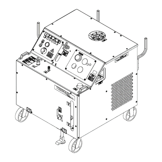
Page 10: Location & Layout Of Controls
Model: 5H31 Hydraulic Power Unit LOCATION & LAYOUT OF CONTROLS 5.3.1 Front Panel Controls Electrical Control Panel See Section 5.3.2 Hydraulic Control Panel See Section 5.3.3 Bypass Valve For loading and unloading the motor driven hydraulic pump Flowmeter Displays the flow from the motor driven hydraulic pump Pump Control Access See Figure 5.3.5 - Hydraulic Pump Controls... -
Page 11: Electrical Control Panel
Model: 5H31 Hydraulic Power Unit 5.3.2 Electrical Control Panel Emergency Stop Removes power to all electrical devices, must turn to reset Stop Switch Turns off the electric motors driving the hydraulic pump and cooling fan Start Switch Turns on the electric motors driving the hydraulic pump and cooling fan Light is illuminated when the electric motors driving the hydraulic pump and cooling fan HPU Power "On"... -
Page 12: Hydraulic Control Panel
Model: 5H31 Hydraulic Power Unit 5.3.3 Hydraulic Control Panel System Pressure Gauge Displays the system pressure on an analog fluid dampened gauge Displays the fluid temperature in the return system on an analog gauge. A warning Pyrometer indicator preset to 160 F (71 C) warns of high operating temperature... -
Page 13: Rear Panel Controls
Model: 5H31 Hydraulic Power Unit 5.3.4 Rear Panel Controls The source of pressurized fluid from the HPU that flows to the aircraft pressure system * Fluid Pressure System through the pressure hose * Fluid Return System Fluid returning to the HPU from the aircraft that flows through the return hoses... -
Page 14: Hydraulic Pump Controls
Model: 5H31 Hydraulic Power Unit 5.3.5 Hydraulic Pump Controls The hydraulic pump flow control and pressure control are located through the pump control access door. Flow Control This control is used to set the maximum flow required from the HPU... -
Page 15: Hand Pump Controls (Option M)
Model: 5H31 Hydraulic Power Unit 5.3.6 Hand Pump Controls (Option M) Reference 5.9 Hand Pump Operation Located inside the front access door is the hand pump handle used for opening and Pump Handle closing the hand pump relief screw and stroking the hand pump arm... -
Page 16: Start Up Procedures
Model: 5H31 Hydraulic Power Unit START UP PROCEDURES 5.4.1 Procedure for First Time or Different Electrical Supply ONLY − Phase Monitor (Options G J Only): Check that the phase monitor light on the instrument panel is not illuminated. If the light is illuminated, change any two of the three input leads at the plug. -
Page 17: Pressure Control Adjustment
Model: 5H31 Hydraulic Power Unit 5.5.2 Pressure Control Adjustment Open bypass valve. Select "Hydraulic Power Unit" position with reservoir selector valve. Start HPU. Close bypass valve. Adjust pressure control for desired pressure; observing the system pressure gauge, read in psi (bars). Be sure the control shaft lock nut is loose during adjustment. -
Page 18: To Easily Purge The Unit Of Air
Model: 5H31 Hydraulic Power Unit 5.6.1 To Easily Purge the Unit of Air Fill reservoir to recommended level. Open bypass valve. Place reservoir selector valve in “Hydraulic Power Unit” position. Start unit and adjust flow control to maximum position. NOTE: If fluid is not flowing, shut off HPU and reference section 8.2 No Flow in Troubleshooting section of Technical Manual Run unit for five (5) minutes and shut off. -
Page 19: High Fluid Temperature Indicator (Option S)
5.12 INFREQUENT HPU USE If the unit is not used frequently Tronair recommends operating the unit monthly. Operating regularly assures that the seals are kept lubricated, eliminates air pockets in the system, reduces moisture in the fluid and helps extend the hose life. -
Page 20: Packaging And Storage
Model: 5H31 Hydraulic Power Unit PACKAGING AND STORAGE PACKAGING REQUIREMENTS Drain hydraulic fluid until level is below the minimum fluid level indicator. Block up the unit on a pallet so the wheels are not touching the pallet or shipping container. -
Page 21: Troubleshooting
Model: 5H31 Hydraulic Power Unit TROUBLESHOOTING The following is a guide to solutions of common problems associated with the HPU. See related Appendix for Hydraulic and Electrical Schematics. If the problem is not resolved using the Troubleshooting information, call the manufacturer for Technical Assistance (See Section 1.3 Manufacturer). -
Page 22: Reduced Flow
Model: 5H31 Hydraulic Power Unit REDUCED FLOW Possible Cause Solution Flow control set too low Increase flow setting Pressure adjustment is set too low Slightly increase pressure setting When system pressure exceeds the compensator control setting, or when the system... -
Page 23: Maintenance
Hydraulic Power Unit MAINTENANCE If the unit is not used frequently Tronair recommends operating the unit monthly. Operating regularly assures that the seals are kept lubricated, eliminates air pockets in the system, reduces moisture in the fluid and helps extend the hose life. -
Page 24: Motor Driven Hydraulic Pump
(See Section 5.9 Sample Valve Operation) Refer to the manufacturer of the specific fluid for your unit to obtain additional information: Model Number ....5H31 Fluid Type ..... Aviation Phosphate Ester, Type IV 12/2023 | Rev. 15... -
Page 25: Filters
Model: 5H31 Hydraulic Power Unit FILTERS 12/2023 | Rev. 15 Page | 20... -
Page 26: Pressure Filter
Model: 5H31 Hydraulic Power Unit 9.5.1 Pressure Filter Replace the filter element any time the clogged filter indicator light (Option R) is triggered or when the pop-up indicator located on the filter head changes to red during operation. Replace the filter element annually to ensure proper cleanliness of the hydraulic system. This is a minimum requirement. -
Page 27: Return Filter
Model: 5H31 Hydraulic Power Unit 9.5.2 Return Filter Replace the return filter element at the same time the pressure filter element is being replaced. Parts List Fluid Type: Aviation Phosphate Ester, Type IV Item Part Number Description HC-2006-350 O-RING (BOWL) -
Page 28: Hand Pump (Option M) Filter
Fluid Type: Aviation Phosphate Ester, Type IV Item Part Number Description HC-2006-144 O-RING (BOWL) BACKUP RING (BOWL) 1, 2, 3 K-3752 KIT, REPLACEMENT FILTER ELEMENT * Part number not released at time of publish. Call Tronair for Part number. 12/2023 | Rev. 15 Page | 23... -
Page 29: Desiccant Air Filter
Model: 5H31 Hydraulic Power Unit 9.5.4 Desiccant Air Filter Replace the desiccant/air filter whenever the material inside the element is pink or reddish in color (see Element Label for details). Parts List Fluid Type: Aviation Phosphate Ester, Type IV Item... -
Page 30: Hydraulic Hoses
Model: 5H31 Hydraulic Power Unit HYDRAULIC HOSES Hoses used on the HPU must be periodically inspected for damage, blisters, leaks, or hose end problems. Any damaged or defective hose should be replaced as soon as possible. Hoses used on Aviation Phosphate Ester, Type IV units have a shorter useful life than hoses used on Mineral Base units. -
Page 31: Instrument Panel
Model: 5H31 Hydraulic Power Unit INSTRUMENT PANEL Refer to Section 9.6 Hydraulic Hoses concerning hose inspection for general maintenance on Item 3 Hose Assembly. Parts List Fluid Type: Aviation Phosphate Ester, Type IV Item Part Number Description See Section 9.7.1 ELECTRIC PANEL See Section 9.7.2... -
Page 32: Electric Panel
Model: 5H31 Hydraulic Power Unit 9.7.1 Electric Panel The Electric Panel does not require regular general maintenance. Parts List Fluid Type: Aviation Phosphate Ester, Type IV Item Component Part Number Description Standard EC-1945-01 LIGHT, DIFFUSED PILOT Standard EC-1951-MN5G POWER, MODULE W/LATCH... -
Page 33: Hydraulic Panel
Model: 5H31 Hydraulic Power Unit 9.7.2 Hydraulic Panel Annual calibration of instrumentation is recommended. See Section 12.0 − Calibration of Instrumentation for details of calibration. Parts List Fluid Type: Aviation Phosphate Ester, Type IV Item Part Number Description HC-1769-02 PYROMETER... -
Page 34: Control Block/Flowmeter
Model: 5H31 Hydraulic Power Unit 9.7.3 Control Block/Flowmeter The Control Block components do not require regular general maintenance. Parts List Fluid Type: Aviation Phosphate Ester, Type IV Item Part Number Description HC-1927-05 NEEDLE VALVE N-2001-18-S-E ELBOW, STRAIGHT THREAD (#12) N-2066-10-S-E... -
Page 35: System Pressure Relief Valve
Model: 5H31 Hydraulic Power Unit 9.7.3.a System Pressure Relief Valve The System Pressure Relief Valve does not require regular general maintenance. It is possible however, for a contaminant to hold the relief valve in a partially open condition. If service is required, the new or repaired relief valve must be reset to 3,750 psig. -
Page 36: Check Valve
Model: 5H31 Hydraulic Power Unit 9.7.3.b Check Valve The Check Valve does not require regular general maintenance. Parts List Fluid Type: Aviation Phosphate Ester, Type IV Item Part Number Description HC-1677 CHECK VALVE HC-2013-910 O-RING, SERIES 3 HC-2006-014 O-RING, SERIES 2... -
Page 37: Reservoir Assembly
Model: 5H31 Hydraulic Power Unit RESERVOIR ASSEMBLY Replace the desiccant air filter whenever the material inside the element is pink or reddish in color (See Element label for details). The Reservoir Assembly does not require regular general maintenance. If periodic inspections for silt are desired, be certain to thoroughly clean the dome cover and surrounding area before removing the dome cover. - Page 38 Model: 5H31 Hydraulic Power Unit RESERVOIR ASSEMBLY (continued) Parts List Fluid Type: Aviation Phosphate Ester, Type IV Item Part Number Description HC-1383-18 SIGHT GAUGE N-2049-20-S-E ELBOW, 90 SWIVEL, #20 HC-1764-02 SELECTOR VALVE, #20 SAE N-2007-28-S-E CONNECTOR, STRAIGHT THREAD #20 SAE...
-
Page 39: Return Manifold Assembly
Model: 5H31 Hydraulic Power Unit RETURN MANIFOLD ASSEMBLY The Return Manifold does not require regular general maintenance. NOTE: DO NOT attempt to adjust the Return System Pressure Relief Valve. See Section 9.9.1 − Return System Pressure Relief Valve for details. -
Page 40: Return System Pressure Relief Valve
Model: 5H31 Hydraulic Power Unit 9.9.1 Return System Pressure Relief Valve The Return System Pressure Relief Valve can be purchased as a preset assembly. If the relief valve is serviced by the end user, the valve must be set to crack at 150+/-7 psig before being re-installed on the HPU. - Page 41 Model: 5H31 Hydraulic Power Unit This page left blank intentionally 12/2023 | Rev. 15 Page | 36...
-
Page 42: Electrical Components
Model: 5H31 Hydraulic Power Unit 9.10 ELECTRICAL COMPONENTS Regularly inspect the external power cord for nicks, cuts, abrasion, and fluid damage. Replace power cord if − damage is found. See Section 10.0 Provision of Spares for recommended spare fuses. Set Item 07 to "Auto" and set "A2" to its corresponding full load amps. Wire per Appendix - Electrical Schematic INS-1608 and wire diagram INS-1746. - Page 43 Model: 5H31 Hydraulic Power Unit 9.10 ELECTRICAL COMPONENTS (continued) Parts List Fluid Type: Aviation Phosphate Ester, Type IV Item Part Number Description EC-1180-24 TERMINAL, RING TONGUE ¼ BOLT HOLE EC-1542-04 FUSE, LP-CC-LOW PEAK 1-6/10A EC-1957 BLOCK, IEC GROUND EC-1532-02 LUG, GROUND G-1251-1050R LOCKWASHER, ¼...
-
Page 44: Electrical Components With 100 Ft Input Cord Option
Model: 5H31 Hydraulic Power Unit 9.10.1 Electrical Components With 100 ft Input Cord Option Regularly inspect the external power cord for nicks, cuts, abrasion, and fluid damage. Replace power cord if damage is found. See Section 11.0 Provision of Spares for recommended spare fuses. - Page 45 Model: 5H31 Hydraulic Power Unit 9.11.1 Electrical Components With 100 ft. Input Cord Option (continued) Parts List Fluid Type: Aviation Phosphate Ester, Type IV Item Part Number Description EC1897 ENCLOSURE, ELECTRICAL G-1159-105516 SCREW, RD HD CRS REC, ¼ - 28 X 1 ¾ LONG G-1250-1050N FLATWASHER, ¼...
- Page 46 Model: 5H31 Hydraulic Power Unit 9.11.1 Electrical Components With 100 ft. Input Cord Option (continued) Parts List Fluid Type: Aviation Phosphate Ester, Type IV Item Part Number Description EC-1961-04 JUMPER, CENTER EC-1961-02 JUMPER, CENTER EC-1961-01 JUMPER, CENTER EC-1826 GUARD, FINGER TOUCHPROOF...
-
Page 47: Heat Exchanger Assembly
Model: 5H31 Hydraulic Power Unit 9.11 HEAT EXCHANGER ASSEMBLY The Heat Exchanger Assembly does not require regular general maintenance. Parts List Fluid Type: Aviation Phosphate Ester, Type IV Item Part Number Description Reference Table below HEAT EXCHANGER N-2463-20-S-E REDUCER, #20 X #12 SAE... -
Page 48: External Components
Model: 5H31 Hydraulic Power Unit 9.12 EXTERNAL COMPONENTS Keep HPU clean. Do not allow labels to become damaged; thusly illegible. Regularly inspect casters and floor locks to ensure safe working condition. Parts List Fluid Type: Aviation Phosphate Ester, Type IV... -
Page 49: Split System Assembly
Model: 5H31 Hydraulic Power Unit 9.13 SPLIT SYSTEM ASSEMBLY Refer to Section 9.6 Hydraulic Hoses concerning hose inspection. Parts List Fluid Type: Aviation Phosphate Ester, Type IV Item Part Number Description N-2464-14-S-E UNION, MALE STRAIGHT THREAD #12 X #16 HC-1908... -
Page 50: Electric Filter Clogging Indicator
Model: 5H31 Hydraulic Power Unit 9.14 ELECTRIC FILTER CLOGGING INDICATOR The Electric Filter Clogging Indicator does not require regular general maintenance. The panel light will illuminate when the clogging indicator senses a 50 psi differential pressure across the filter element. Installing a new filter element will eliminate the clogged condition. -
Page 51: Additional Features
Model: 5H31 Hydraulic Power Unit 9.15 ADDITIONAL FEATURES − 9.15.1 Voltage/Phase Monitor (Options G The Voltage/Phase Monitor does not require regular general maintenance. The panel indicator light will illuminate if a tripped condition exists. If the Voltage/Phase Monitor is causing the HPU to shut off, verify the Phase Monitor −... -
Page 52: Electric Reservoir Level (Option L)
Model: 5H31 Hydraulic Power Unit 9.15.2 Electric Reservoir Level (Option L) The Electric Reservoir Level switch does not require regular general maintenance. Panel indicator lights will indicate low or high fluid level. NOTE: Wire per Electrical Schematic INS-1608. Reference Wiring Diagram INS-1608. Reference 9.7.1 Electrical Panel for Panel Light. - Page 53 Model: 5H31 Hydraulic Power Unit This page left blank intentionally. 12/2023 | Rev. 15 Page | 48...
-
Page 54: Hand Pump (Option M)
Model: 5H31 Hydraulic Power Unit 9.15.3 Hand Pump (Option M) Refer to Section 9.6 Hydraulic Hoses concerning hose inspection for general maintenance on Items 5, 10, 12, and − 14 hose assemblies. Refer to Section 9.5.3 Hand Pump (Optional) Filter . - Page 55 Model: 5H31 Hydraulic Power Unit 9.15.3 Hand Pump (Option M) (continued) Parts List Fluid Type: Aviation Phosphate Ester, Type IV Item Part Number Description HC-2146 PRESSURE GAUGE V-1887 LABEL, HAND PUMP PRESSURE N-2001-11-S-E ELBOW, #8 SAE X #8 JIC FLARE...
-
Page 56: Two Stage Pump With Relief
Model: 5H31 Hydraulic Power Unit 9.15.3.a Two Stage Pump with Relief 12/2023 | Rev. 15 Page | 51... - Page 57 Model: 5H31 Hydraulic Power Unit 9.15.3.a Two Stage Pump with Relief (continued) Parts List Fluid Type: Aviation Phosphate Ester, Type IV Item Part Number Description 519-000 CXC-990022-001 BODY 505-001 PLUG, VALVE BODY 571-121 PISTON, BYPASS ASSEMBLY 508-000 PIVOT 566-125 PISTON L.P...
-
Page 58: Calibration Port (Option Q)
Model: 5H31 Hydraulic Power Unit 9.15.4 Calibration Port (Option Q) Refer to Section 9.6 Hydraulic Hoses concerning hose inspection. Parts List Fluid Type: Aviation Phosphate Ester, Type IV Item Part Number Description HC-1900-02 NEEDLE VALVE HC-1122 KIT, PANEL MOUNTING (MVK-4) -
Page 59: Electric Over-Temperature (Option S)
Model: 5H31 Hydraulic Power Unit 9.15.5 Electric Over-Temperature (Option S) The Electric Over-Temperature switch does not require regular general maintenance. However, automatic shut down due to high fluid temperature is a indication that maintenance or training may be needed elsewhere. -
Page 60: Replacement Labels Parts Lists
Model: 5H31 Hydraulic Power Unit 9.16 REPLACEMENT LABELS PARTS LISTS 9.16.1 Base Unit Part Number Description V-1001 "MADE IN USA" V-1033-01 "TRONAIR" V-1050 ISO ELECTRICAL SHOCK SYMBOL V-1365 "SYSTEM PRESSURE" V-1366 "HPU BY-PASS VALVE" V-1882 CONTROL PANEL LIGHTS V-1884 "FLOWMETER"... -
Page 61: Pyrometer
Website: www.tronair.com For Spare Parts, Operations & Service Manuals or Service Needs: Scan the QR code or visit Tronair.com/aftermarket 10.2 RECOMMENDED SPARE PARTS LISTS It is recommended that the following spare parts be kept on hand and available for immediate use during maintenance. -
Page 62: Calibration Of Instrumentation
CALIBRATION OF INSTRUMENTATION All gauges on the Hydraulic Power Unit can be either returned to Tronair for calibration or certified by the end user if proper calibration equipment is available. Gauges returned to Tronair for calibration will be tested with standards traceable to N.I.S.T. -
Page 63: Analog Pressure Gauge (Hand Pump Pressure- Option M Only )
Minimum Acceptable Maximum Acceptable Calibration gauge ( F) ( F) ( F) ( F) 160 (159-161) 12.0 IN SERVICE SUPPORT − Contact Tronair, Inc. for technical services and information. See Section 1.3 Manufacturer. 12/2023 | Rev. 15 Page | 58... - Page 64 If warranty coverage is approved, either replacement parts will be sent or the product will have to be returned to Tronair for repairs. If the product is to be returned, a Return Material Authorization (RMA) number will be issued for reference purposes on any shipping documents.
- Page 65 APPENDIX I Hydraulic Schematic (INS-1602)
- Page 69 APPENDIX II Electrical Schematic (INS-1608 and INS-2016)
- Page 75 APPENDIX III Wiring Diagram (INS-1746 and INS-2144)
- Page 79 L E T R E V I S I O N E C N D W N C H K D A T E T H I S D R A W I N G I S T H E P R O P E R T Y O F T R O N A I R , I N C . I T I S F U R N I S H E D T O Y O U F O R C O N F I D E N T I A L I N F O R M A T I O N P U R P O S E S O N L Y A N D I S N O T T O B E D I S C L O S E D T O A N Y O N E E L S E O R R E P R O D U C E D O R U S E D F O R M A N U F A C T U R I N G P U R P O S E S...
- Page 81 APPENDIX IV Declaration of Conformity...
- Page 83 ISO 4021:1997 ARP 1247B NFPA 70/NEC 1999 Identification of person empowered to sign on behalf of the Manufacturer: Quality Assurance Representative Tronair, Inc. Phone: (419) 866-6301 | 800-426-6301 1 Air Cargo Pkwy East Web: www.tronair.com Swanton, OH 43558 Email: sales@tronair.com...
- Page 85 APPENDIX V Lincoln Motor Manual...
- Page 91 APPENDIX VI Oilgear Type PVWJ Pump Manuals...
- Page 165 APPENDIX VII Safety Data Sheet (SDS) Hydraulic Fluid...
- Page 187 APPENDIX VIII Instrument Certification Notice...
- Page 189 Re-calibration should be done on a periodic basis as dictated by the end user's quality system or other overriding requirements. Note that Tronair, Inc. does not supply certificates of calibration on flow meters or pyrometers unless requested at the time of placed order. These instruments are considered reference indicators only and are not critical to the test(s) being performed on the aircraft.
Need help?
Do you have a question about the 5H31 and is the answer not in the manual?
Questions and answers