Table of Contents
Advertisement
Quick Links
OPERATION & SERVICE MANUAL
5JX1 Series
5J11, 5J21, 5J31, 5J41
Hydraulic Power Units
06/2023 − Rev. 04
For Spare Parts, Operations & Service Manuals or Service Needs
Scan the QR code or visit Tronair.com/aftermarket
Tronair, Inc.
Phone: (419) 866-6301 | 800-426-6301
1 Air Cargo Pkwy East
Web: www.tronair.com
Swanton, OH 43558
Email: sales@tronair.com
Advertisement
Table of Contents

Related Manuals for Tronair 5JX1 Series


Summary of Contents for Tronair 5JX1 Series
- Page 1 5J11, 5J21, 5J31, 5J41 Hydraulic Power Units 06/2023 − Rev. 04 For Spare Parts, Operations & Service Manuals or Service Needs Scan the QR code or visit Tronair.com/aftermarket Tronair, Inc. Phone: (419) 866-6301 | 800-426-6301 1 Air Cargo Pkwy East Web: www.tronair.com...
- Page 2 REVISION DATE TEXT AFFECTED 12/2017 Original release 08/2021 Added section 5.13 Infrequent HPU Use and updated 9.0 Maintenance 02/2023 Major revision 06/2023 Updated 9.6 Hydraulic Hoses...
-
Page 3: Table Of Contents
Model: 5J41 Hydraulic Power Unit TABLE OF CONTENTS PAGE PRODUCT INFORMATION .............................. 1 DESCRIPTION ..............................1 MODEL & SERIAL NUMBER .......................... 1 MANUFACTURER ............................1 FUNCTION ..............................1 REQUIREMENTS ............................1 SAFETY INFORMATION ..............................1 USAGE AND SAFETY INFORMATION ......................1 EXPLANATION OF WARNING &... - Page 4 Model: 5J41 Hydraulic Power Unit 5.13.1 Infrequent HPU Use Start Up Procedure ....................... 18 PACKAGING AND STORAGE ............................19 PACKAGING REQUIREMENTS........................19 HANDLING ..............................19 PACKAGING PROTECTION ......................... 19 LABELING OF PACKAGING ......................... 19 STORAGE COMPATIBILITY ......................... 19 STORAGE ENVIRONMENT .......................... 19 STORAGE SPACE AND HANDLING FACILITIES ..................
- Page 5 Model: 5J41 Hydraulic Power Unit 9.15.5 Pyrometer (Option K) Label ........................... 73 9.15.6 Hand Pump (Option M) Labels ........................73 9.15.7 Calibration Port (Option Q) Labels ......................... 73 9.15.8 Back-Pressure Valve with Sight Glass (Option T) Label ................73 10.0 PROVISION OF SPARES ...............................
-
Page 6: Product Information
Model: 5J41 Hydraulic Power Unit This product cannot be modified without the written approval of Tronair, Inc. Any modifications done without written approval voids all warranties and releases Tronair, Inc., it suppliers, distributors, employees, or financial institutions from any liability from consequences that may occur. -
Page 7: Component Safety Features
Model: 5J41 Hydraulic Power Unit COMPONENT SAFETY FEATURES • • Pump/Motor coupling guard Control circuit fuses • • Sheet metal panels Motor overload protection • Pressure and return system relief valves FUNCTIONAL SAFETY FEATURES • • Emergency shut off switch Calibration port shut off valve •... -
Page 8: Training
Model: 5J41 Hydraulic Power Unit TRAINING TRAINING REQUIREMENTS The employer of the operator is responsible for providing a training program sufficient for the safe operation of the HPU. TRAINING PROGRAM The employer provided operator training program should cover safety procedures concerning use of the HPU in and around the intended aircraft at the intended aircraft servicing location. -
Page 9: Physical
Model: 5J41 Hydraulic Power Unit 5.2.2 Physical Weight (Dry) ......1,650 lbs (748.43 kg) Width ........51 in (129.5 cm) Height ........48.75 in (124 cm) Depth ........55 in (140 cm) Power Cord ......50 ft (15.24 m) long Pressure Hoses .... -
Page 10: Filters
Model: 5J41 Hydraulic Power Unit 5.2.5 Filters Pressure ....... 2 micron rating, non-bypass high collapse microglass type. Non-cleanable element. Return ........5 micron rating, 15 psi (1.03 bar) bypass microglass type. Non-cleanable element. Hand Pump (Option M) ..2 micron rating, non-bypass microglass type. Non-cleanable element. Air/Desiccant ...... -
Page 11: Location & Layout Of Controls
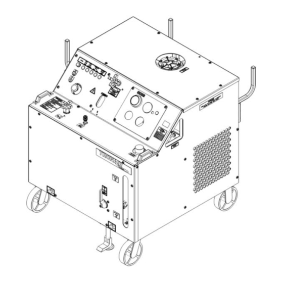
Model: 5J41 Hydraulic Power Unit LOCATION & LAYOUT OF CONTROLS 5.3.1 Front Panel Controls Electrical Control Panel See Section 5.3.2 Hydraulic Control Panel See Section 5.3.3 Bypass Valve For loading and unloading the motor driven hydraulic pump Flowmeter Displays the flow from the motor driven hydraulic pump Pump Control Access See Figure 5.3.5 - Hydraulic Pump Controls Reservoir Selector... -
Page 12: Electrical Control Panel
Model: 5J41 Hydraulic Power Unit 5.3.2 Electrical Control Panel Emergency Stop Removes power to all electrical devices, must turn to reset Stop Switch Turns off the electric motors driving the hydraulic pump and cooling fan Start Switch Turns on the electric motors driving the hydraulic pump and cooling fan Light is illuminated when the electric motors driving the hydraulic pump and cooling HPU Power "On"... -
Page 13: Hydraulic Control Panel
Model: 5J41 Hydraulic Power Unit 5.3.3 Hydraulic Control Panel System Pressure Gauge Displays the system pressure on an analog fluid dampened gauge Displays the fluid temperature in the return system on an analog gauge. A Pyrometer (Option K) warning indicator preset to 160° F (71° C) warns of high operating temperature Allows for calibration of the system pressure gauge up to the operating pressure of Pressure Gauge Calibration Port HPU. -
Page 14: Rear Panel Controls
Model: 5J41 Hydraulic Power Unit 5.3.4 Rear Panel Controls The source of pressurized fluid from the HPU that flows to the aircraft pressure * Fluid Pressure System system through the pressure hose * Fluid Return System Fluid returning to the HPU from the aircraft that flows through the return hoses Pressure Fluid Filter Filters the pressurized fluid before it flows to the aircraft pressure system A sample valve is provided to obtain a fluid sample for analysis. -
Page 15: Hydraulic Pump Controls
Model: 5J41 Hydraulic Power Unit 5.3.5 Hydraulic Pump Controls The hydraulic pump flow control and pressure control are located on the front panel. Flow Control This control is used to set the maximum flow required from the HPU Pressure Control The pressure control is used to set the system pressure of the HPU during operation 02/2023 | Rev. -
Page 16: Hand Pump Controls (Option M)
Model: 5J41 Hydraulic Power Unit 5.3.6 Hand Pump Controls (Option M) Reference 6.9 Hand Pump Operation Located inside the front access door is the hand pump handle used for opening and Pump Handle closing the hand pump relief screw and stroking the hand pump arm Accessed through the front panel opening, this screw allows opening and closing of Hand Pump Relief Screw the hand pump hydraulic circuit using the hand pump handle... -
Page 17: Split System Controls (Option C)
Model: 5J41 Hydraulic Power Unit 5.3.7 Split System Controls (Option C) Reference 6.7 Split System Operation Pressure Manifold Houses the pressure valves Used to turn on and off the flow to separate aircraft systems. Always use in either Fluid Pressure Ball Valve fully open or fully closed position;... -
Page 18: Split System Crossover Check Controls (Option D)
Model: 5J41 Hydraulic Power Unit 5.3.8 Split System Crossover Check Controls (Option D) Reference 6.8 Split System Crossover Check Operation Pressure Gauge Displays the pressure in each aircraft system Hose Assembly Connects HPU to aircraft pressure system Ball Valve Turns on and off the fluid for taking contamination samples Crossover Check Manifold Houses the valves and gauges Used to turn on and off the flow to the separate aircraft pressure systems. -
Page 19: Start Up Procedures
Model: 5J41 Hydraulic Power Unit START UP PROCEDURES 5.4.1 Procedure for First Time or Different Electrical Supply ONLY − Phase Monitor (Options G J Only): Check that the phase monitor light on the instrument panel is not illuminated. If the light is illuminated, change any two of the three input leads at the plug. Once the phase monitor light is not illuminated with power attached, check for proper motor rotation. -
Page 20: Pressure Control Adjustment
Model: 5J41 Hydraulic Power Unit 5.5.2 Pressure Control Adjustment Open bypass valve. Select "Hydraulic Power Unit" position with reservoir selector valve. Start HPU. Close bypass valve. Adjust pressure control for desired pressure; observing the system pressure gauge, read in psi (bar). Be sure the control shaft lock nut is loose during adjustment. -
Page 21: To Easily Purge The Unit Of Air
Model: 5J41 Hydraulic Power Unit 5.6.1 To Easily Purge the Unit of Air Fill reservoir to recommended level. Open bypass valve. Place reservoir selector valve in “Hydraulic Power Unit” position. Start unit and adjust flow control to maximum position. NOTE: If fluid is not flowing, shut off HPU and reference 8.2 No Flow Run unit for five (5) minutes and shut off. -
Page 22: Hand Pump Operation (Option M)
Model: 5J41 Hydraulic Power Unit HAND PUMP OPERATION (Option M) The Hand Pump Option allows for filling the reservoir (low pressure) or static testing of components or system (high pressure). The hand pump circuit is separate from the main hydraulic system; a separate filter and hose are attached to the back panel of the HPU. -
Page 23: Infrequent Hpu Use
5.13 INFREQUENT HPU USE If the unit is not used frequently Tronair recommends operating the unit monthly. Operating regularly assures that the seals are kept lubricated, eliminates air pockets in the system, reduces moisture in the fluid and helps extend the hose life. -
Page 24: Packaging And Storage
Model: 5J41 Hydraulic Power Unit PACKAGING AND STORAGE PACKAGING REQUIREMENTS Drain hydraulic fluid until level is below the minimum fluid level indicator. Block up the unit on a pallet so the wheels are not touching the pallet or shipping container. Plug all hose ends. -
Page 25: Trouble Shooting
Model: 5J41 Hydraulic Power Unit TROUBLE SHOOTING The following is a guide to solutions of common problems associated with the HPU. See related Appendices for Hydraulic and Electrical Schematics. If the problem is not resolved using the trouble shooting information, call the manufacturer for Technical Assistance (See Section 1.3 Manufacturer). -
Page 26: Reduced Flow
Model: 5J41 Hydraulic Power Unit REDUCED FLOW Possible Cause Solution Flow control set too low Increase flow setting. Pressure adjustment is set too low Slightly increase pressure setting. When system pressure exceeds the compensator control setting, or when the Pressure compensator control is system no longer requires flow, the control de-strokes the pump while maintaining reducing pump output the preset pressure. -
Page 27: Maintenance
Hydraulic Power Unit MAINTENANCE If the unit is not used frequently Tronair recommends operating the unit monthly. Operating regularly assures that the seals are kept lubricated, eliminates air pockets in the system, reduces moisture in the fluid and helps extend the hose life. -
Page 28: Hydraulic Pump
N-2924-08 N-2924-08 N-2924-08 CONNECTOR, IN-LINE ORFICE N-2202-03-S N-2202-03-S N-2202-03-S ELBOW, SWIVEL NUT 9.3.1 Hydraulic Pump Replacement Kits List For replacement parts and seals, contact Tronair with hydraulic pump part number and serial number. 02/2023 | Rev. 03 Page | 23... -
Page 29: Hydraulic Fluid
Model: 5J41 Hydraulic Power Unit HYDRAULIC FLUID Any time an unusual color, smell or visual indicator is noticed with the hydraulic fluid, a sample analysis should be − performed to determine the condition of the fluid. (See Section 5.10 Sample Valve Operation) Refer to the manufacturer of the specific fluid for your unit to obtain additional information: Model Number Fluid Type... -
Page 30: Pressure Filter
Model: 5J41 Hydraulic Power Unit 9.5.1 Pressure Filter Replace the filter element any time the clogged filter indicator light (Option R) is triggered or when the pop-up indicator located on the filter head changes to red during operation. Replace the filter element annually to ensure proper cleanliness of the hydraulic system. This is a minimum requirement. -
Page 31: Return Filter
Model: 5J41 Hydraulic Power Unit 9.5.2 Return Filter Replace the return filter element at the same time the pressure filter element is being replaced. Parts List Model Number Fluid Type 5J11 ......MIL-PRF-5606 5J21 ......MIL-PRF-83282 5J31 ......Aviation Phosphate Ester, Type IV and V 5J41 ...... -
Page 32: Hand Pump (Option M) Filter
Model: 5J41 Hydraulic Power Unit 9.5.3 Hand Pump (Option M) Filter Replacement of the hand pump filter element is dictated by frequency of use and the cleanliness of the fluid, along with the environment to which the HPU is exposed. Changing the hand pump filter element at the same time as the pressure filter element will ensure a regular maintenance schedule. -
Page 33: Desiccant Air Filter
Model: 5J41 Hydraulic Power Unit 9.5.4 Desiccant Air Filter Replace the desiccant/air filter whenever the material inside the element is pink or reddish in color (see Element Label for details). Parts List All Models - All Fluid Types Item Part Number Description HC-1763 FILTER ELEMENT... -
Page 34: Hydraulic Hoses
Model: 5J41 Hydraulic Power Unit HYDRAULIC HOSES Hoses used on the HPU must be periodically inspected for damage, blisters, leaks, or hose end problems. Any damaged or defective hose should be replaced as soon as possible. Parts List Model Number Fluid Type 5J11 ...... -
Page 35: Instrument Panel
Model: 5J41 Hydraulic Power Unit INSTRUMENT PANEL Refer to Section 10.6 Hydraulic Hoses concerning hose inspection for general maintenance on Hose Assembly. Parts List All Models - All Fluid Types Item Part Number Description See Section 9.7.1 ELECTRIC PANEL See Section 9.7.2 HYDRAULIC PANEL See Section 9.6 ASSEMBLY, HOSE #4... -
Page 36: Electric Panel
Model: 5J41 Hydraulic Power Unit 9.7.1 Electric Panel The Electric Panel does not require regular general maintenance. Parts List All Models - All Fluid Types Item Component Part Number Description Standard EC-1945-01 LIGHT, DIFFUSED PILOT Standard EC-1951-MN5G POWER, MODULE W/LATCH Option EC-1945-03 LIGHT, DIFFUSED PILOT... -
Page 37: Hydraulic Panel
Model: 5J41 Hydraulic Power Unit 9.7.2 Hydraulic Panel − Annual calibration of instrumentation is recommended. See Section 11.0 Calibration of Instrumentation for details of calibration. Parts List Model Number Fluid Type 5J11 ......MIL-PRF-5606 5J21 ......MIL-PRF-83282 5J31 ......Aviation Phosphate Ester, Type IV and V 5J41 ...... -
Page 38: Control Block/Flowmeter
Model: 5J41 Hydraulic Power Unit 9.7.3 Control Block/Flowmeter The Control Block components do not require regular general maintenance. Parts List Model Number Fluid Type 5J11 ......MIL-PRF-5606 5J21 ......MIL-PRF-83282 5J31 ......Aviation Phosphate Ester, Type IV and V 5J41 ......MIL-PRF-87257 5J11 &... -
Page 39: System Pressure Relief Valve
Model: 5J41 Hydraulic Power Unit 9.7.3.a System Pressure Relief Valve The System Pressure Relief Valve does not require regular general maintenance. It is possible however, for a contaminant to hold the relief valve in a partially open condition. If service is required, the new or repaired relief valve must be reset to 4, 250 psig. -
Page 40: Check Valve
Model: 5J41 Hydraulic Power Unit 9.7.3.b Check Valve The Check Valve does not require regular general maintenance. Parts List Model Number Fluid Type 5J11 ......MIL-PRF-5606 5J21 ......MIL-PRF-83282 5J31 ......Aviation Phosphate Ester, Type IV and V 5J41 ......MIL-PRF-87257 5J11 &... -
Page 41: Bypass Valve
Model: 5J41 Hydraulic Power Unit 9.7.3.c Bypass Valve The Bypass Valve does not require regular general maintenance. Parts List Model Number Fluid Type 5J11 ......MIL-PRF-5606 5J21 ......MIL-PRF-83282 5J31 ......Aviation Phosphate Ester, Type IV and V 5J41 ......MIL-PRF-87257 5J11 &... -
Page 42: Flow Control
Model: 5J41 Hydraulic Power Unit 9.7.4 Flow Control Parts List Model Number Fluid Type 5J11 ......MIL-PRF-5606 5J21 ......MIL-PRF-83282 5J31 ......Aviation Phosphate Ester, Type IV and V 5J41 ......MIL-PRF-87257 5J11 & 5J21 5J31 5J41 Item Part Number Part Number Part Number Description... -
Page 43: Pressure Control
Model: 5J41 Hydraulic Power Unit 9.7.5 Pressure Control Parts List Model Number Fluid Type 5J11 ......MIL-PRF-5606 5J21 ......MIL-PRF-83282 5J31 ......Aviation Phosphate Ester, Type IV and V 5J41 ......MIL-PRF-87257 5J11 & 5J21 5J31 5J41 Item Part Number Part Number Part Number Description... -
Page 44: Reservoir Assembly
Model: 5J41 Hydraulic Power Unit RESERVOIR ASSEMBLY Replace the desiccant air filter whenever the material inside the element is pink or reddish in color (See Element label for details). The Reservoir Assembly does not require regular general maintenance. If periodic inspections for silt are desired, be certain to thoroughly clean the dome cover and surrounding area before removing the dome cover. - Page 45 Model: 5J41 Hydraulic Power Unit RESERVOIR ASSEMBLY (continued) Parts List Model Number Fluid Type 5J11 ......MIL-PRF-5606 5J21 ......MIL-PRF-83282 5J31 ......Aviation Phosphate Ester, Type IV and V 5J41 ......MIL-PRF-87257 5J11 & 5J21 5J31 5J41 Item Part Number Part Number Part Number Description...
-
Page 46: Return Manifold Assembly
Model: 5J41 Hydraulic Power Unit RETURN MANIFOLD ASSEMBLY − Refer to Section 9.5.2 Return Filter for information on changing filter element. NOTE: DO NOT attempt to adjust the Return System Pressure Relief Valve. See Section 9.9.1 − Return System Pressure Relief Valve for details. 02/2023 | Rev. - Page 47 Model: 5J41 Hydraulic Power Unit RETURN MANIFOLD ASSEMBLY (continued) Parts List Model Number Fluid Type 5J11 ......MIL-PRF-5606 5J21 ......MIL-PRF-83282 5J31 ......Aviation Phosphate Ester, Type IV and V 5J41 ......MIL-PRF-87257 5J11 & 5J21 5J31 5J41 Item Part Number Part Number Part Number Description...
-
Page 48: Return System Pressure Relief Valve
Model: 5J41 Hydraulic Power Unit 9.9.1 Return System Pressure Relief Valve The Return System Pressure Relief Valve can be purchased as a preset assembly. If the relief valve is serviced by the end user, the valve must be set to crack at 150+/-7 psig before being re-installed on the HPU. Parts List Model Number Fluid Type... -
Page 49: Pressure Filter Assembly (Single System)
Model: 5J41 Hydraulic Power Unit 9.10 PRESSURE FILTER ASSEMBLY (Single System) Refer to Section 10.5.1 for information on changing filter element. Parts List Model Number Fluid Type 5J11 ......MIL-PRF-5606 5J21 ......MIL-PRF-83282 5J31 ......Aviation Phosphate Ester, Type IV and V 5J41 ...... -
Page 50: Electrical Components
Model: 5J41 Hydraulic Power Unit 9.11 ELECTRICAL COMPONENTS Regularly inspect the external power cord for nicks, cuts, abrasion, and fluid damage. Replace power cord if − damage is found. See Section 10.0 Provision of Spares for recommended spare fuses. Set Item 07 to "Auto" and set "A2" to its corresponding full load amps. Wire per Appendix - Electrical Schematic INS-1725 and wire diagram INS-1747. - Page 51 Model: 5J41 Hydraulic Power Unit 9.11 ELECTRICAL COMPONENTS (continued) Parts List Item Part Number Description G-1159-105516 Screw, Round Head Cross Rec, ¼ - 28 x 1 ¾ LG G-1250-1050N Flatwasher, ¼ Narrow G-1202-1055 Stopnut, Elastic ¼ - 28 G-1180-105006 Screw, HH TPG Type F ¼ EC-1956-02 Block, IEC Terminal (Red) EC-1803...
- Page 52 Model: 5J41 Hydraulic Power Unit 9.11 ELECTRICAL COMPONENTS (continued) THE FOLLOWING PARTS ARE APPLICATION SPECIFIC Be sure to locate the correct voltage and hertz of the unit before selecting the part 60 Hz Applications Item Description EC-1924-02 EC-1924-02 Lug Set, Terminal EC-1920 EC-1920 EC-1525...
- Page 53 Model: 5J41 Hydraulic Power Unit This page left blank intentionally 02/2023 | Rev. 03 Page | 48...
-
Page 54: Electrical Components With 100 Ft Input Cord Option
Model: 5J41 Hydraulic Power Unit 9.11.1 Electrical Components With 100 ft Input Cord Option Regularly inspect the external power cord for nicks, cuts, abrasion, and fluid damage. Replace power cord if − damage is found. See Section 10.0 Provision of Spares for recommended spare fuses. Set Item 07 to "Auto"... - Page 55 Model: 5J41 Hydraulic Power Unit 9.11.1 Electrical Components With 100 ft Input Cord Option (continued) Parts List Item Part Number Description G-1159-105516 Screw, RD HD CRS REC, ¼ - 28 x 1 ¾ LG G-1250-1050N Flatwasher, ¼ Narrow G-1202-1055 Stopnut, Elastic ¼ - 28 G-1180-105006 Screw, HH TPG Type F ¼...
- Page 56 Model: 5J41 Hydraulic Power Unit 9.11.1 Electrical Components With 100 ft Input Cord Option (continued) THE FOLLOWING PARTS ARE APPLICATION SPECIFIC Be sure to locate the correct voltage and hertz of the unit before selecting the part Parts List 60 HZ Applications Item Description EC-1920...
-
Page 57: Heat Exchanger Assembly
Model: 5J41 Hydraulic Power Unit 9.12 HEAT EXCHANGER ASSEMBLY The Heat Exchanger Assembly does not require regular general maintenance. Voltage Frequency Part Number 208v 60 Hz HC-2136-01 230v 60 Hz HC-2136-01 380v 60 Hz HC-2136-01 460v 60 Hz HC-2136-01 575v 60 Hz HC-2136-02 200v... -
Page 58: External Components
Model: 5J41 Hydraulic Power Unit 9.13 EXTERNAL COMPONENTS Keep HPU clean. Do not allow labels to become damaged; thusly illegible. Regularly inspect casters and floor locks to ensure safe working condition. Parts List All Models - All Fluid Types Item Part Number Description S-1889-00... -
Page 59: Additional Features
Model: 5J41 Hydraulic Power Unit 9.14 ADDITIONAL FEATURES 9.14.1 50 ft (15.24 m) Hoses (Option B) Refer to Section 9.6 Hydraulic Hoses concerning hose inspection. Model Number Fluid Type 5J11 ......MIL-PRF-5606 5J21 ......MIL-PRF-83282 5J31 ......Aviation Phosphate Ester, Type IV and V 5J41 ...... -
Page 60: Split System (Option C)
Model: 5J41 Hydraulic Power Unit 9.14.2 Split System (Option C) Refer to Section 9.6 Hydraulic Hoses concerning hose inspection. Parts List Model Number Fluid Type 5J11 ......MIL-PRF-5606 5J21 ......MIL-PRF-83282 5J31 ......Aviation Phosphate Ester, Type IV and V 5J41 ...... -
Page 61: Crossover Check (Option D)
Model: 5J41 Hydraulic Power Unit 9.14.3 Crossover Check (Option D) Refer to Section 9.6 Hydraulic Hoses concerning hose inspection. Annual calibration of instrumentation is − recommended. See Section 11.0 Calibration of Instrumentation for details of gauge calibration. Parts List Model Number Fluid Type 5J11 ...... -
Page 62: Hour Meter (Options E And F)
Model: 5J41 Hydraulic Power Unit 9.14.4 Hour Meter (Options E and F) The Hour Meter does not require regular general maintenance. NOTE: Wire Hour Meter per Appendix − Electrical Schematic INS-1725. Reference Appendix − Wire Diagram INS-1747. Parts List All Models - All Fluid Types Part Number Application Description... -
Page 63: Voltage/Phase Monitor (Options G − J)
Model: 5J41 Hydraulic Power Unit − 9.14.5 Voltage/Phase Monitor (Options G The Voltage/Phase Monitor does not require regular general maintenance. The panel indicator light will illuminate if a tripped condition exists. If the Voltage/Phase Monitor is causing the HPU to shut off, verify the Phase Monitor −... -
Page 64: Pyrometer (Option K)
Model: 5J41 Hydraulic Power Unit 9.14.6 Pyrometer (Option K) − Refer to Section 11.6 Analog Temperature Gauge when calibration of the pyrometer is desired. 5J11 & 5J21 5J31 5J41 Item Part Number Part Number Part Number Description N-2463-16-S-B N-2463-16-S-E N-2463-16-S-V REDUCER FITTING HC-1769-01 HC-1769-02... -
Page 65: Electric Reservoir Level (Option L)
Model: 5J41 Hydraulic Power Unit 9.14.7 Electric Reservoir Level (Option L) The Electric Reservoir Level switch does not require regular general maintenance. Panel indicator lights will indicate low or high fluid level. NOTE: Wire per Appendix − Electrical Schematic INS-1725. Reference Appendix − Wiring Diagram INS- 1747. -
Page 66: Hand Pump (Option M)
Model: 5J41 Hydraulic Power Unit 9.14.8 Hand Pump (Option M) Refer to Section 9.6 Hydraulic Hoses concerning hose inspection for general maintenance on Items 5, 10, 12, and − 14 hose assemblies. Refer to Section 9.5.3 Hand Pump (Optional) Filter. 04/2013 | Rev. - Page 67 Model: 5J41 Hydraulic Power Unit 9.14.8 Hand Pump (Option M)(continued) Parts List Model Number Fluid Type 5J11 ......MIL-PRF-5606 5J21 ......MIL-PRF-83282 5J31 ......Aviation Phosphate Ester, Type IV and V 5J41 ......MIL-PRF-87257 5J11 & 5J21 5J31 5J41 Item Part Number Part Number Part Number...
-
Page 68: Towing Trailer (Option N)
Model: 5J41 Hydraulic Power Unit 9.14.9 Towing Trailer (Option N) Air Pressure: 55 psi Parts List All Models - All Fluid Types Item Part Number Description Z-5775-01 WELDMENT, FRAME BOLT, HH, 3/8 – 16 X 1 LONG G-1100-107010 J-3669-01 BRACKET, FIXED WHEEL G-1302-21 PIN, CLEVIS 1 OD X 6 TR-1894-01... -
Page 69: Calibration Port (Option Q)
Model: 5J41 Hydraulic Power Unit 9.14.10 Calibration Port (Option Q) Refer to Section 9.6 Hydraulic Hoses concerning hose inspection. Parts List Model Number Fluid Type 5J11 ......MIL-PRF-5606 5J21 ......MIL-PRF-83282 5J31 ......Aviation Phosphate Ester, Type IV and V 5J41 ...... -
Page 70: Electric Filter Clogging Indicator (Option R)
Model: 5J41 Hydraulic Power Unit 9.14.11 Electric Filter Clogging Indicator (Option R) The Electric Filter Clogging Indicator does not require regular general maintenance. The panel light will illuminate when the clogging indicator senses a 98 psi differential pressure across the filter element. Installing a new filter element will eliminate the clogged condition. -
Page 71: Electric Over-Temperature (Option S)
Model: 5J41 Hydraulic Power Unit 9.14.12 Electric Over-Temperature (Option S) The Electric Over-Temperature switch does not require regular general maintenance. However, automatic shut down due to high fluid temperature is a indication that maintenance or training may be needed elsewhere. NOTE: Wire per Appendix −... -
Page 72: Return Back-Pressure With Sight Gauge (Option T) Available On Model 5J31 Only
Model: 5J41 Hydraulic Power Unit 9.14.13 Return Back-Pressure with Sight Gauge (Option T) available on model 5J31 Only Annual calibration of instrumen − tation is recommended. See Section 11.0 Calibration of Instrumentation for details of gauge calibration. Refer − to Section 9.6 Hydraulic Hoses concerning hose inspection. - Page 73 Model: 5J41 Hydraulic Power Unit 9.14.13 Return Back-Pressure with Sight Gauge (Option T) available on model 5J31 Only (continued) Available on Model 5J31 Only Parts List Fluid Type: Aviation Phosphate Ester, Type IV & V Item Part Number Description G-1250-1100W Flatwasher, Wide N-2710-S-E...
-
Page 74: 9.14.13.A Item 16 Sight Glass Assembly Exploded View
Model: 5J41 Hydraulic Power Unit 9.14.13.a Item 16 Sight Glass Assembly Exploded View Available on Model 5J31 Only Parts List Fluid Type: Aviation Phosphate Ester, Type IV & V Item Part Number Description Z-5634 Sight, Modified Flow HC-2006-113 O-ring, Series 2 HC-2013-911 O-ring, Series 3 HS-1006... -
Page 75: Return Sight Gauge (Option U)
Model: 5J41 Hydraulic Power Unit 9.14.14 Return Sight Gauge (Option U) Refer to Section 10.6 Hydraulic Hoses concerning hose inspection. Annual calibration of instrumentation is recommended Parts List Model Number Fluid Type 5J11 ......MIL-PRF-5606 5J21 ......MIL-PRF-83282 5J31 ......Aviation Phosphate Ester, Type IV and V 5J41 ...... -
Page 76: Return Back Pressure (Option V)
Model: 5J41 Hydraulic Power Unit 9.14.15 Return Back Pressure (Option V) Refer to Section 9.6 Hydraulic Hoses concerning hose inspection. Annual calibration of instrumentation is recommended. See Section 11.0 – Calibration of Instrumentation for details of gauge calibration. Parts List Model Number Fluid Type 5J11 ...... -
Page 77: Replacement Labels Parts Lists
Model: 5J41 Hydraulic Power Unit 9.15 REPLACEMENT LABELS PARTS LISTS 9.15.1 Base Unit Part Number Description V-1001 "MADE IN USA" V-1033 "TRONAIR" V-1050 ISO ELECTRICAL SHOCK SYMBOL V-1365 "SYSTEM PRESSURE" V-1366 "HPU BY-PASS VALVE" V-1374 "ROTATION" V-1375 "PRESSURE INCREASE/FLOW INCREASE"... -
Page 78: Split System (Option C) And Crossover Check (Option D) Labels
Model: 5J41 Hydraulic Power Unit 9.15.4 Split System (Option C) and Crossover Check (Option D) Labels Part Number Description V-2004 "SYSTEM 1 PRESSURE" V-2005 "SYSTEM 2 PRESSURE" V-2006 "SYSTEM 1 RETURN" V-2007 "SYSTEM 2 RETURN" 9.15.5 Pyrometer (Option K) Label Part Number Description V-1886... - Page 79 Website: www.tronair.com For Spare Parts, Operations & Service Manuals or Service Needs: Scan the QR code or visit Tronair.com/aftermarket 10.2 RECOMMENDED SPARE PARTS LISTS It is recommended that the following spare parts be kept on hand and available for immediate use during maintenance.
- Page 80 CALIBRATION OF INSTRUMENTATION All gauges on the Hydraulic Power Unit can be either returned to Tronair for calibration or certified by the end user if proper calibration equipment is available. Gauges returned to Tronair for calibration will be tested with standards traceable to N.I.S.T.
- Page 81 APPENDIX I Hydraulic Schematic (INS-2620)
- Page 83 L E T R E V I S I O N E C N D W N C H K D A T E T H I S D R A W I N G I S T H E P R O P E R T Y O F T R O N A I R , I N C . I T I S F U R N I S H E D T O Y O U R E T U R N F O R C O N F I D E N T I A L I N F O R M A T I O N P U R P O S E S O N L Y A N D I S N O T T O B E D I S C L O S E D...
- Page 85 APPENDIX II Electrical Schematic (INS-1608 and INS-2016...
- Page 89 APPENDIX III Wiring Diagram (INS-1746 and INS-2144)
- Page 93 L E T R E V I S I O N E C N D W N C H K D A T E T H I S D R A W I N G I S T H E P R O P E R T Y O F T R O N A I R , I N C . I T I S F U R N I S H E D T O Y O U F O R C O N F I D E N T I A L I N F O R M A T I O N P U R P O S E S O N L Y A N D I S N O T T O B E D I S C L O S E D T O A N Y O N E E L S E O R R E P R O D U C E D O R U S E D F O R M A N U F A C T U R I N G P U R P O S E S...
- Page 95 APPENDIX IV Instrument Certification Notice...
- Page 97 Re-calibration should be done on a periodic basis as dictated by the end user's quality system or other overriding requirements. Note that Tronair, Inc. does not supply certificates of calibration on flow meters or pyrometers unless requested at the time of placed order. These instruments are considered reference indicators only and are not critical to the test(s) being performed on the aircraft.
Need help?
Do you have a question about the 5JX1 Series and is the answer not in the manual?
Questions and answers