
Related Manuals for ETC Eos Apex 20


Summary of Contents for ETC Eos Apex 20
- Page 1 Eos Family User Manual Version 3.1.1 Eos Apex 5, 10, & 20 Eos Ti, Gio, Gio @5 Ion Xe, Ion Xe 20 Element 2 4250M1210-3.1.1 RevA 2022-03...
- Page 2 To view a list of ETC trademarks and patents, go to etcconnect.com/ip. All other trademarks, both marked and not marked, are the property of their respective owners. ETC intends this document, whether printed or electronic, to be provided in its entirety.
-
Page 3: Table Of Contents
Table of Contents Introduction Using this Manual Register Your Console Online Eos Family User Forums Help from ETC Technical Services Other Reference Materials Important Concepts Console Overview Eos Apex 5 Overview Eos Apex 10 Overview Eos Apex 20 Overview Eos Ti Overview... - Page 4 Display Control and Navigation Live and Blind Displays Playback Status Display Direct Selects Encoders Moving Light Controls Fader Configuration Virtual Keyboard Face Panel Shortcuts Hotkeys sACN Output Viewer Managing Show Files About Managing Show Files Create a New Show File Open an Existing Show File Merging Show Files Printing a Show File...
- Page 5 Attribute Section Database Section Augment3d Section Using Device List Clearing the Patch Update Profile Fixture Editor Setup About Setup System Settings User Settings Device Settings Console Status Display Manual Control About Manual Control Using Channel Faders On Element 2 Selecting Channels Setting Intensity Manual Control of Non-intensity Parameters (NPs) Home...
- Page 6 Flash Groups About Groups Recording Groups Live Selecting Groups Opening the Group List Using Groups as a Channel Collector About Fan Fanning Parameter Data Fan From the Command Line Fanning References Fanning Timing and Delays Using Subgroups with Fan Mark About Mark AutoMark Referenced Marks...
- Page 7 Presets About Presets Preset Options Storing Presets Live Recalling Presets Effects in Presets Editing Presets Live Using the Preset List Editing Presets in Blind Using By Type Presets Removing Channels from a Preset Deleting Presets Presets and Palettes Fader Properties Single Cue Lists About Single Cue List Basic Cueing...
- Page 8 Partial Filters Clearing Filters Storing Data with Record Filters Multiple Cue Lists About Working With Multiple Cue Lists Recording to a New Cue List Using [Go To Cue] with Multiple Cue Lists Advanced Manual Control About Advanced Manual Control Using [Copy To] Using [Recall From] Using {Make Null} Using {Make Manual}...
- Page 9 Deleting Parts from Multipart Cues Effects About Effects The Effect List Effects Editor Effect Status Display Effect Channel Display Step Effects Absolute Effects Effect Background Value Modification Beats Per Minute Multiple Intensity HTP Effects Relative Effects Preprogrammed Rainbow Effects Apply an Existing Effect Editing Effects Live Stopping Effects Query and Group Effect...
- Page 10 Submasters About Submasters Paging Submasters Recording a Submaster Submaster List Editing Submasters Submaster Properties Submaster Fader and Button Configuration Submaster Information Labeling a Submaster Loading Submasters Using Bump Button Timing With Submasters Controlling Subfades Manually Execute List [Freeze] and [Stop Effect] on Submasters Moving and Copying Submasters Releasing Content From a Submaster Updating a Submaster...
- Page 11 [About] Macro [About] IFCB Palettes [About] Presets [About] Color Path [About] Live Curves About Curves Creating a Curve Editing Curves Applying a Curve To Channels In Patch Curves Applied to Cues Applying a Curve To Scroller Fans Deleting Curves Snapshots About Snapshots Recording Snapshots Recalling Snapshots...
- Page 12 Magic Sheets About Magic Sheets Magic Sheet Browser Magic Sheet List Display Tools Navigating a Magic Sheet Creating and Editing Magic Sheets Limited Expand Mode Examples of Magic Sheets Augment3d About Augment3d Hardware and Software Requirements Running Augment3d Augment3d Key Terms Navigation in Augment3d Augment3d Control Mode Augment3d Edit Mode...
- Page 13 Partitioned Control About Partitioned Control How to Use Partitions Setting Up Partitioned Control Partition List Creating New Partitions Deleting Partitions Using Partitions Partitions in Playback Partitions on Cue Lists Flexichannel in Partitioned Control Multi-Console About Multi-Console Multi-Console Terms Multi-console Setup Synchronized Backup Mirror Mode Eos Configuration Utility...
- Page 14 Real Time Clock (RTC) Analog Inputs sACN Input MIDI Show Control String Interface MIDI Raw Open Sound Control (OSC) Eos Family Show Control Capabilities Advanced OSC Eos OSC Keys Regulatory Apex 5, 10, and 20, Apex Remote Processor, Eos Remote Interface, and Windows 10- based Ion Xe, Ion Xe20, Ion Xe RPU, Gio@5, and Element 2 ETCnomad Puck Eos Apex, Eos Ti, Gio, Gio @5, Ion Xe, Ion Xe 20, and Element 2 User Manual...
-
Page 15: Introduction
Introduction Using this Manual Register Your Console Online Eos Family User Forums Help from ETC Technical Services Other Reference Materials Important Concepts Introduction... -
Page 16: Using This Manual
Online Eos Family User Forums You are encouraged to visit and participate in the ETC Eos Family User Forum, accessible from the ETC website, etcconnect.com. This gives you access to an online community of Eos Family users where you can read about other users’ experiences, suggestions, and questions regarding the product as well as submit your own. -
Page 17: Help From Etc Technical Services
3. Follow the registration instructions provided by the community page. Help from ETC Technical Services If you are having difficulties and your problem is not addressed by this document, try the ETC support website at support.etcconnect.com or the main ETC website at etcconnect.com. If none of these resources are sufficient, contact ETC Technical Services directly at one of the offices identified below. -
Page 18: Other Reference Materials
The following resources are recommended: John Huntington, Show Networks and Control Systems, (Brooklyn, NY:Zircon Designs • Press, 2012) ETC Support Articles, available at support.etcconnect.com/ETC. • Important Concepts Before using your console, you should read and familiarize yourself with the concepts defined below. - Page 19 A fixture is defined as a group of related addresses that together control a device. An example of a fixture would be an ETC Revolution. This automated fixture contains 31 parameters that together allow you to perform various functions such as pan and tilt. Each of these attributes is addressed by a different output.
- Page 20 • • • Level • Actions from the direct selects • Parameters and Parameter Categories Eos family consoles divide fixture parameters into four major parameter categories: Intensity, Focus, Color, and Beam. These are the parameters in each category: Intensity - Intensity •...
- Page 21 Tracking Mode When you create a new cue, any unchanged channel parameter data from the previous cue is tracked into the new specified cue. Any changes in this new cue will also track forward into subsequent cues until a move instruction or a block flag is encountered. In the example below, the gray boxes indicate tracked values and the white boxes indicate move instructions.
- Page 22 Move Instruction A move instruction is any change to a parameter from its previous stored value, such as changes to a channel’s intensity, pan or tilt, color mixing, etc. Manual Data Manual data is any value set for a channel via the command line. Manual data will remain at its value until a move instruction is provided for it.
- Page 23 This rule is not followed when executing an out-of-sequence cue. An out-of-sequence cue is any cue that is recalled via [Go To Cue], a Link instruction, or manually changing the pending cue. In general applications, the entire contents of the cue (both moves and tracks) will be asserted on an out-of-sequence cue.
- Page 24 LTP is applicable to any parameter of any channel. LTP output is based on the most recent move instruction issued to the channel parameter. Any new values sent to the channel will supersede any previous values, regardless of the level supplied. Eos family consoles determine the LTP value for a channel, which is overridden by any HTP input values that are higher than the LTP instruction.
-
Page 25: Console Overview
Chapter 1 Console Overview Inside this section you will find general descriptions of your console and various areas of the user interface. Eos Apex 5 Overview Eos Apex 10 Overview Eos Apex 20 Overview Eos Ti Overview Gio Overview Gio @5 Overview... - Page 26 Eos Apex 5 Layout 1. Power button 13. Mini encoders • • 2. USB-A & USB-C (data) 14. Level wheel • • 3. Internal touchscreen 15. Keyboard / accessory tray • • 4. Keypad 16. USB-A (power only) • • 5. Keypad touchscreen 17.
- Page 27 Internal Touchscreens Apex consoles are designed with one (Apex 5) or two (Apex 10 and 20) internal touchscreen displays, supporting haptic feedback or pressure-sensitive touch. The main touchscreens may be used to display and control show data. They may also be used as a variety of other virtual controls and displays.
- Page 28 Hardkeys Backlit hardkeys are provided on the face panel. The brightness level for those keys can be Brightness Settings (on page 219) adjusted in the When your console has been idle for 10 minutes, the backlights will fade down by 10%. Any key press on the face panel keypad or an external keyboard, a move of the mouse, or an interaction with a touchscreen will return the keys to their set brightness level.
- Page 29 Additional Targets & Functions Other hardkeys provide options for a variety of common console functions and shortcuts to various Blind displays. Keypad Touchscreen Apex consoles include a haptic touch-enabled screen above the keypad that can be configured to control custom direct selects or magic sheets. Softkeys and a gear icon to access screen settings are docked at the bottom of this display.
- Page 30 IO garage. Any ETC Gadget II or Response Show Control Gateway can be added to the garage and connected internally via USB for local input / output of DMX, MIDI, SMPTE, and other protocols.
- Page 31 Task lights can also be controlled by holding down [Displays] and rolling the level wheel. WARNING: This device contains a lithium battery. Battery may explode if mistreated. Do not recharge, disassemble or dispose of in fire. Eos Apex 5 Capacities Output Parameters 24,576 •...
- Page 32 Record Targets 10,000 Groups • 10,000 x 4 Palettes (Intensity, Focus, Color and Beam) • 10,000 Presets • 10,000 Effects • 99,999 Macros • 10,000 Snapshots • 10,000 Curves • 10,000 Color Paths • Faders 1 dedicated motorized master playback pair, with Go and Stop/Back •...
- Page 33 Eos Apex 10 Components Power Button The power button on the front of the console is used to power up or power down. A separate hard power switch, located on the rear panel, can be used to disconnect power from the console’s internal components.
- Page 34 {Monitor Arrangement...} (on page 556) For monitor configuration, see Hardkeys Backlit hardkeys are provided on the face panel. The brightness level for those keys can be adjusted in the Brightness Settings (on page 219) When your console has been idle for 10 minutes, the backlights will fade down by 10%. Any key press on the face panel keypad or an external keyboard, a move of the mouse, or an interaction with a touchscreen will return the keys to their set brightness level.
- Page 35 Additional Targets & Functions Other hardkeys provide options for a variety of common console functions and shortcuts to various Blind displays. Keypad Touchscreen Apex consoles include a haptic touch-enabled screen above the keypad that can be configured to control custom direct selects or magic sheets. Softkeys and a gear icon to access screen settings are docked at the bottom of this display.
- Page 36 IO garage. Any ETC Gadget II or Response Show Control Gateway can be added to the garage and connected internally via USB for local input / output of DMX, MIDI, SMPTE, and other protocols.
- Page 37 control for external monitors. CAUTION: The USB data ports cannot be used for charging devices. Charging Ports Two USB A ports, capable of delivering 5A / 12.5W of power each, are available for charging devices. One is located under the encoder display on the front right of the desk. The other is located under the faders on the front left of the desk (Apex 5), or inside the accessory drawer (Apex 10 and 20).
- Page 38 Record Targets 10,000 Groups • 10,000 x 4 Palettes (Intensity, Focus, Color and Beam) • 10,000 Presets • 10,000 Effects • 99,999 Macros • 10,000 Snapshots • 10,000 Curves • 10,000 Color Paths • Faders 1 dedicated motorized master playback pair, with Go and Stop/Back •...
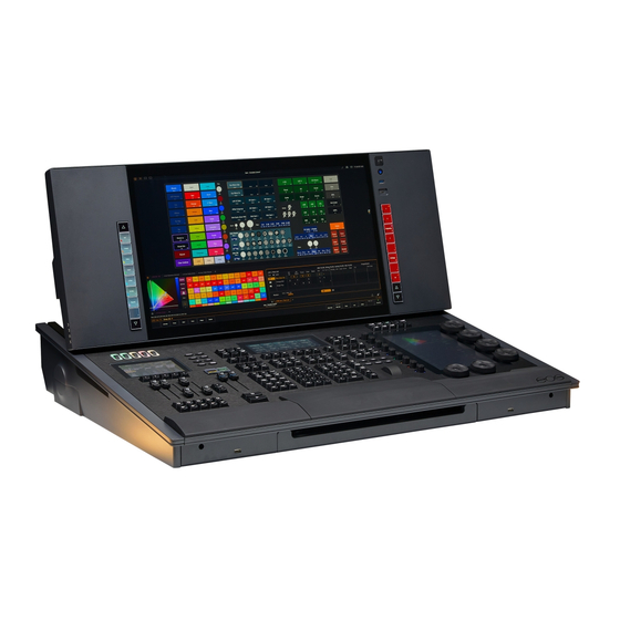
- Page 39 Eos Apex 20 Components Power Button The power button on the front of the console is used to power up or power down. A separate hard power switch, located on the rear panel, can be used to disconnect power from the console’s internal components.
- Page 40 {Monitor Arrangement...} (on page 556) For monitor configuration, see Hardkeys Backlit hardkeys are provided on the face panel. The brightness level for those keys can be adjusted in the Brightness Settings (on page 219) When your console has been idle for 10 minutes, the backlights will fade down by 10%. Any key press on the face panel keypad or an external keyboard, a move of the mouse, or an interaction with a touchscreen will return the keys to their set brightness level.
- Page 41 Additional Targets & Functions Other hardkeys provide options for a variety of common console functions and shortcuts to various Blind displays. Keypad Touchscreen Apex consoles include a haptic touch-enabled screen above the keypad that can be configured to control custom direct selects or magic sheets. Softkeys and a gear icon to access screen settings are docked at the bottom of this display.
- Page 42 IO garage. Any ETC Gadget II or Response Show Control Gateway can be added to the garage and connected internally via USB for local input / output of DMX, MIDI, SMPTE, and other protocols.
- Page 43 control for external monitors. CAUTION: The USB data ports cannot be used for charging devices. Charging Ports Two USB A ports, capable of delivering 5A / 12.5W of power each, are available for charging devices. One is located under the encoder display on the front right of the desk. The other is located under the faders on the front left of the desk (Apex 5), or inside the accessory drawer (Apex 10 and 20).
- Page 44 Record Targets 10,000 Groups • 10,000 x 4 Palettes (Intensity, Focus, Color and Beam) • 10,000 Presets • 10,000 Effects • 99,999 Macros • 10,000 Snapshots • 10,000 Curves • 10,000 Color Paths • Faders 1 dedicated motorized master playback pair, with Go and Stop/Back •...
-
Page 45: Eos Ti Overview
Eos Ti Overview This page provides an overview of the physical layout, components, and capacities of the Eos Ti console. Eos Ti Layout Console Overview... - Page 46 Eos Ti Components Power Button The power button on the front of the console is used to power up or power down. A separate hard power switch, located on the rear panel, can be used to disconnect power from the console’s internal components.
- Page 47 Gio @ 5, Ion Xe, and Element 2 support up to two external Windows 7 compatible Display Port monitors. Monitor Specifications Windows 10 consoles Display resolutions of 1920x1080 (minimum) to 3480x2160 (maximum) are supported • Each display may be utilized in landscape or portrait mode •...
- Page 48 Targets (3) The target controls provide options for altering a variety of record targets, as well as shortcuts to various Blind displays. Display & Navigation (4) The display and navigation keys provide quick access to common displays, formatting, paging, and navigation within displays. Encoder Categories (5) The encoder category buttons allow expanded control of a variety of fixture parameters, along with additional softkey options where applicable.
- Page 49 Six hardkeys are also available for encoder control. These encoder paging keys control intensity, focus, color, shutter, image, and form. Pressing any of these will change the parameters controlled by the encoders. To view other available encoder pages, simply press the encoder paging keys to advance the pages.
- Page 50 Dimming Task Lights Task lights can be dimmed from within Eos, under Setup > Device > Brightness Settings. The {Desk Lamp} slider has a range of 0% (dimmest) to 100% (brightest). The default setting is 0%. The console will set the desk lamp to this setting on startup of the application. See Brightness Settings (on page 219) for more information.
-
Page 51: Gio Overview
Gio Overview This page provides an overview of the physical layout, components, and capacities of the Gio console. Gio Layout Console Overview... - Page 52 Gio Components Power Button The power button on the front of the console is used to power up or power down. A separate hard power switch, located on the rear panel, can be used to disconnect power from the console’s internal components. CAUTION: It is recommended that you safely power down the console via Displays >...
- Page 53 Monitor Specifications Windows 10 consoles Display resolutions of 1920x1080 (minimum) to 3480x2160 (maximum) are supported • Each display may be utilized in landscape or portrait mode • Multi-touch display support requires the following: • Data connection via USB-A or USB-C cable per multi-touch monitor •...
- Page 54 Targets (3) The target controls provide options for altering a variety of record targets, as well as shortcuts to various Blind displays. Display & Navigation (4) The display and navigation keys provide quick access to common displays, formatting, paging, and navigation within displays. Encoder Categories (5) The encoder category buttons allow expanded control of a variety of fixture parameters, along with additional softkey options where applicable.
- Page 55 Six hardkeys are also available for encoder control. These encoder paging keys control intensity, focus, color, shutter, image, and form. Pressing any of these will change the parameters controlled by the encoders. To view other available encoder pages, simply press the encoder paging keys to advance the pages.
- Page 56 Dimming Task Lights Task lights can be dimmed from within Eos, under Setup > Device > Brightness Settings. The {Desk Lamp} slider has a range of 0% (dimmest) to 100% (brightest). The default setting is 0%. The console will set the desk lamp to this setting on startup of the application. See Brightness Settings (on page 219) for more information.
-
Page 57: Gio @5 Overview
Gio @5 Overview This page provides an overview of the physical layout, components, and capacities of the Gio @5 console. Gio @5 Layout Console Overview... - Page 58 Gio @5 Components Power Button The power button on the front of the console is used to power up or power down. A separate hard power switch, located on the rear panel, can be used to disconnect power from the console’s internal components.
- Page 59 Monitor Specifications Windows 10 consoles Display resolutions of 1920x1080 (minimum) to 3480x2160 (maximum) are supported • Each display may be utilized in landscape or portrait mode • Multi-touch display support requires the following: • Data connection via USB-A or USB-C cable per multi-touch monitor •...
- Page 60 Targets (3) The target controls provide options for altering a variety of record targets, as well as shortcuts to various Blind displays. Display & Navigation (4) The display and navigation keys provide quick access to common displays, formatting, paging, and navigation within displays. Encoder Categories (5) The encoder category buttons allow expanded control of a variety of fixture parameters, along with additional softkey options where applicable.
- Page 61 Level Wheel The level wheel adjusts intensity up or down for any selected channels. With channels selected, roll the wheel up to increase intensity, or down to decrease it. The level wheel can also provide additional functions when combined with various other console keys.
- Page 62 Dimming Task Lights Task lights can be dimmed from within Eos, under Setup > Device > Brightness Settings. The {Desk Lamp} slider has a range of 0% (dimmest) to 100% (brightest). The default setting is 0%. The console will set the desk lamp to this setting on startup of the application. See Brightness Settings (on page 219) for more information.
-
Page 63: Ion Xe Overview
Ion Xe Overview This page provides an overview of the physical layout, components, and capacities of the Ion Xe console. Ion Xe Layout Ion Xe Components Power Button The power button on the front of the console is used to power up or power down. A separate hard power switch, located on the rear panel, can be used to disconnect power from the console’s internal components. - Page 64 CAUTION: It is recommended that you safely power down the console via Displays > Power Off Device before disconnecting power from the console. CAUTION: Power cord must be connected using an earth ground connection. WARNING: Before servicing your console, you must switch off the power on the rear panel and disconnect the power cord completely.
- Page 65 Hardkeys Backlit hardkeys are provided on the face panel. The brightness level for those keys can be Brightness Settings (on page 219) adjusted in the When your console has been idle for 10 minutes, the backlights will fade down by 10%. Any key press on the face panel keypad or an external keyboard, a move of the mouse, or an interaction with a touchscreen will return the keys to their set brightness level.
- Page 66 Main Playbacks The main playback fader pair, located to the left of the control keypad, is a split cross-fader pair. The button or buttons located directly above the playbacks load content to the playbacks. The two buttons below control the [Go] and [Stop/Back] functions. Load Buttons Ion Xe 20 lacks dedicated load buttons for assigning a specified target to a specified fader, other than for the main playbacks.
- Page 67 USB Ports One USB port is provided on the front of the console to connect any USB storage device. Additional USB ports on the rear panel (and in the keyboard tray, when present) of the console connect peripherals such as an alphanumeric keyboard, pointing device, or touchscreen control for external monitors.
-
Page 68: Ion Xe 20 Overview
10,000 Effects • 99,999 Macros • 10,000 Snapshots • 10,000 Curves • 10,000 Color Paths • Faders 1 dedicated main playback pair, with Go and Stop/Back • 200 configurable cue playbacks, with Go and Stop/Back • 999 configurable submasters, with Bump and Assert channel select •... - Page 69 Ion Xe 20 Components Power Button The power button on the front of the console is used to power up or power down. A separate hard power switch, located on the rear panel, can be used to disconnect power from the console’s internal components.
- Page 70 Multi-touch display support requires the following: • Data connection via USB-A or USB-C cable per multi-touch monitor • Windows Human Interface Device (HID) compliant touch displays, utilizing Windows • standard driver Displays must process five or more points of simultaneous touch •...
- Page 71 Display & Navigation (4) The display and navigation keys provide quick access to common displays, formatting, paging, and navigation within displays. Encoder Categories (5) The encoder category buttons allow expanded control of a variety of fixture parameters, along with additional softkey options where applicable. Additional Targets & Functions The remaining hardkeys provide options for a variety of common console functions and shortcuts to various Blind displays.
- Page 72 To output, connect one 5 pin XLR cable per port. The first port will default to outputting the first universe of DMX, addresses 1-512, the second port to the second universe, outputting addresses 513-1024, and so on. Output (on page 211) for information on reconfiguring the DMX ports.
- Page 73 Ion Xe 20 Capacities Output Parameters 2,048 (Min) • 12,288 (Max) • Channel Counts 32,768 channels (can be any number from 1 to 99,999) • Cues and Cue List 999 cue lists • 10,000 cues • Record Targets 10,000 Groups •...
-
Page 74: Element 2 Overview
Element 2 Overview This page provides an overview of the physical layout, components, and capacities of the Element 2 console. Element 2 Layout Element 2 Components Power Button The power button on the front of the console is used to power up or power down. A separate hard power switch, located on the rear panel, can be used to disconnect power from the console’s internal components. - Page 75 CAUTION: It is recommended that you safely power down the console via Displays > Power Off Device before disconnecting power from the console. CAUTION: Power cord must be connected using an earth ground connection. WARNING: Before servicing your console, you must switch off the power on the rear panel and disconnect the power cord completely.
- Page 76 Hardkeys Hardkeys are provided on the face panel, divided into several sections based on their functionality. Keypad (1) The numeric keypad allows you to type numbers for channel or target selection via the command line, along with modifier keys to alter your selection. Level Controls (2) The level controls provide options for altering the intensity levels of channels, along with a number of other non-intensity parameters / targets.
- Page 77 The button or buttons located directly above the playbacks load content to the playbacks. The two buttons below control the [Go] and [Stop/Back] functions. Faders In addition to the master playbacks, banks of configurable faders are provided. The faders may be configured as playbacks, submasters, grandmasters, timing masters, effects masters, targets, or target lists.
- Page 78 CAUTION: The USB ports cannot be used for charging devices. Task Lights Littlites® You may connect Littlites to the back of your console. Dimming Task Lights Task lights can be dimmed from within Eos, under Setup > Device > Brightness Settings. The {Desk Lamp} slider has a range of 0% (dimmest) to 100% (brightest).
- Page 79 Faders 1 dedicated main playback pair, with Go and Stop/Back • 40 faders with 80 configurable buttons • 999 configurable submasters, with Bump and Assert channel select • Console Overview...
-
Page 80: Ion Classic Overview
Ion Classic Overview This page provides an overview of the physical layout, components, and capacities of the Ion Classic console. Ion Classic Layout Eos Apex, Eos Ti, Gio, Gio @5, Ion Xe, Ion Xe 20, and Element 2 User Manual... - Page 81 Display Port can use an active adapter to VGA, DVI, or HDMI. DVI-I can be converted to VGA with a passive adapter. Note: Output to 4K resolution monitors may affect console performance. ETC recommends an external monitor resolution of 1024 or lower. For monitor configuration, see {Monitor Arrangement...} (on page 556)
- Page 82 Hardkeys Hardkeys are provided on the face panel, divided into several sections based on their functionality. Keypad (1) The numeric keypad allows you to type numbers for channel or target selection via the command line, along with modifier keys to alter your selection. Level Controls (2) The level controls provide options for altering the intensity levels of channels, along with a number of other non-intensity parameters / targets.
- Page 83 Softkeys (6) The softkey buttons allow physical control of the onscreen softkey options, which change dynamically based on the command line and active tab to offer additional commands not available on hardkeys. Additional Targets & Functions The remaining hardkeys provide options for a variety of common console functions and shortcuts to various Blind displays.
- Page 84 Ethernet Ports Ethernet ports are for connecting to a network switch, network gateways, and accessory devices. Each port is on a separate NIC, and can be configured to directly output network- based lighting control protocols such as sACN or Art-Net. Output Protocols (on page 562) for more information.
- Page 85 Cues and Cue List 999 cue lists • 10,000 cues • Record Targets 10,000 Groups • 10,000 x 4 Palettes (Intensity, Focus, Color and Beam) • 10,000 Presets • 10,000 Effects • 99,999 Macros • 10,000 Snapshots • 10,000 Curves •...
-
Page 86: Element Classic Overview
Element Classic Overview This page provides an overview of the physical layout, components, and capacities of the Element Classic console. Element Classic Layout Element Classic Components Power Button The power button on the front of the console is used to power up or power down. A separate hard power switch, located on the rear panel, can be used to disconnect power from the console’s internal components. - Page 87 Display Port can use an active adapter to VGA, DVI, or HDMI. DVI-I can be converted to VGA with a passive adapter. Note: Output to 4K resolution monitors may affect console performance. ETC recommends an external monitor resolution of 1024 or lower. For monitor configuration, see {Monitor Arrangement...} (on page 556)
- Page 88 Targets (3) The target controls provide options for altering a variety of record targets, as well as shortcuts to various Blind displays. Display & Navigation (4) The display and navigation keys provide quick access to common displays, formatting, paging, and navigation within displays. Softkeys (5) The softkey buttons allow physical control of the onscreen softkey options, which change dynamically based on the command line and active tab to offer additional commands not...
- Page 89 To output, connect one 5 pin XLR cable per port. The first port will default to outputting the first universe of DMX, addresses 1-512, the second port to the second universe, outputting addresses 513-1024, and so on. Output (on page 211) for information on reconfiguring the DMX ports.
- Page 90 Channel Counts 250 or 500 channels (any number from 1 to 99,999) • Cues and Cue List Up to 10,000 cues • 1 Active Playback • 1 Cue List • Record Targets 1,000 Groups • 1,000 Presets • 1,000 x 4 Palettes (Intensity, Focus, Color and Beam) •...
-
Page 91: Cleaning Your Console
If this does not clean the console sufficiently, you may apply some window cleaner (containing ammonia is fine) to the cloth and repeat the process until clean. More information about cleaning your console is available at the ETC Support Site, support.etcconnect.com. - Page 92 Eos Apex, Eos Ti, Gio, Gio @5, Ion Xe, Ion Xe 20, and Element 2 User Manual...
-
Page 93: System Basics
Chapter 2 System Basics About System Basics Power Up the Console Power Down the Console The Central Information Area (CIA) Browser Softkeys Displays Display Control and Navigation Live and Blind Displays Playback Status Display Direct Selects Encoders Moving Light Controls Fader Configuration Virtual Keyboard Face Panel Shortcuts... - Page 94 Note: You can go straight to the welcome screen by adjusting a setting in the ECU. Open in "Shell" E.C.U. (on page 554) in the ECU appendix. Power Down the Console 1. After saving your show (see Saving the Current Show File (on page 153) ), in the browser menu select Power Off Device.
- Page 95 Collapse/ Expand the CIA It is possible to collapse the CIA from view. To do this, you can click the arrow icon above the CIA. The CIA will collapse from view, exposing a larger viewing area of whatever display is visible above the CIA.
-
Page 96: Browser
When collapsed, only the {All NPs}, {All Speed}, and {Expand Arrow} buttons will be displayed. Labeling [Label] is used to attach an alphanumeric label to an object such as cues, channels, submasters, etc. [Label] [Label] when appended to a record target command, clears the current label. This includes show file labels. - Page 97 Using the Browser To use the browser, you must first draw focus to it by touching anywhere in the browser area of the CIA. If the browser is not visible, pressing [Displays]>{Browser} will bring up the browser. When focus is on the browser, the window border highlights in gold. The paging keys will now control selection in the browser.
- Page 98 Clear Functions You can access the various clear options from the browser by selecting {Clear} from the main browser menu. The clear functions window will open in the CIA. From this menu you can select one of the available clear options by clicking on the desired button in the CIA.
-
Page 99: Softkeys
Patch 1 to 1 vs Clear Patch Using {Patch 1 to 1} will clear your patch and set it to a 1-to-1 patch. Using {Clear Patch} will only clear out the patch. Locking the Face Panel It is possible to lock out the face panel, which prevents any actions from the command line or CIA. - Page 100 Workspaces Workspaces offer independent display control on all of your connected monitors. Each workspace can be individually configured with any of the layout, display, and control options available in the Workspace Layout Menu (on page 90) Every monitor can have up to three workspaces, identified by the numbered workspace icons in the upper left corner of any monitor.
- Page 101 White text in the tab indicates a Display Tab, and magenta text indicates a Control Tab. Tab Numbers All Display and Control Tabs have fixed under which they open (for example, “Live” opens under Tab 1, “Patch” under Tab 12, and “Color Picker” under Tab 27). These numbers are identified on the Home Screen in each icon.
- Page 102 35. Fader List Display 36. Fader Configuration 37. sACN Output Viewer 38. Augment3d 39. Custom Direct Select 40. Encoder Mapping 99. Diagnostics 100. User Manual Display Tabs The following displays can be selected, and they will open in a new tab in the selected frame: The following displays can have multiple instances open: Channel (Summary) •...
-
Page 103: Display Control And Navigation
Tab Tools Every frame has a tab tools menu gear icon in the lower left corner of the frame. Selecting this icon will open the tab tools menu, which provides options for opening and closing tabs in that frame. You can double-click or right-click a tab in focus to also see this menu. The following is a list of menu options. - Page 104 From the Home Screen Workspace Layout Menu (below) shows all of the available displays for quick selection. Click on the {+} button by the tabs to access the home screen. From the Browser Open and navigate the browser as described in Using the Browser (on page 83) .
- Page 105 This screen consists of four general areas, each offering different display-related options. Display and Control Icons Clicking on an icon will open the appropriate display or control in a new tab. Display Tabs Control Tabs Layout Options These tools offer you greater flexibility in the number of tabs you can view in any given workspace.
- Page 106 The grid includes the following tools: Adds a horizontal split, dividing the associated frame horizontally into upper and lower rows. Inserts a vertical split, dividing the associated frame vertically into left and right columns. Drag left or right to freely adjust the width of the associated frames. Double-press to reset to the default horizontal size.
- Page 107 Note: On-board touchscreens are locked, and their arrangement cannot be changed. Close All Tabs In This Workspace Closes all of the tabs in the active workspace on the active monitor only. Reset This Workspace Closes all tabs and frames and resets the layout for the active workspace to a single frame displaying theWorkspace Layout Menu, from which you can select new tabs to open.
- Page 108 To expand the Live / Blind tab to up to two additional monitors, press [Expand] & [Page • Right]. Once you are in an expanded mode, hitting [Expand] contracts the tab by one monitor. To remove all displays from the monitor, press [Expand] & [Page Left]. •...
- Page 109 The following displays have clickable support: Show Control List • Cue List • Playback Status Display • Palette Lists • Sub List • Preset List • Effect List • Group List • Snapshot List • Curve List • Partition List •...
-
Page 110: Live And Blind Displays
Press the automated fixture beams icon to close the display when opened. Pop-up Snapshots This option displays your favorite snapshots in a small pop-up window for quick access. Select a snapshot to recall it. Favorite is an option that can be selected or deselected when recording a snapshot. - Page 111 Using [Format] Live / Blind has multiple formats. When first opened, it opens in its default view, which is the Table View (on the next page) . The default view can be set in the Live and Blind Configuration Menu (on page 103) .
- Page 112 Table View Table view is available in Live or Blind. Unlike summary view, table view displays the fixture type associated with channels and details about each channel’s category and parameter levels. In Live, table view displays all active channel data being output from Eos. In Blind, it will display all data for a single record target (cue, preset, palette) depending on what is viewed.
- Page 113 In {Preview} mode, the following softkeys are available: {Previous} - previews the last cue run from the selected cue list. • {Pending} - previews the pending cue from the selected cue list. • The following examples show other functions that are available in Preview: {Preview}[Next] will allow you to preview the cue higher than the one currently selected.
- Page 114 Number of cue lists the channel appears in. • Number of cues the channel appears in. • Number of cue moves from zero. • Number of submasters that channel appears in. • Maximum channel level. • Note: Right-click on the CIU tab to limit see which channels are used with a specified cue list.
- Page 115 Note: The color and text conventions apply regardless of the format of Live/ Blind being used (see Using [Format] (on page 97)). Note: When manual channels are used, there will be an advisory that says "Manual Channels" in red in the upper left hand corner of any Live display. Most of the channels in the above image are conventional channels (intensity is the only available parameter).
- Page 116 Note: A decimal will display at the end of a master channel when flexi cells off is on. Color Indicators Eos uses color to indicate the selection state and information about channel/parameter levels. Channel Numbers/ Channel Headers Gray number Unpatched channel number. •...
- Page 117 _ Underlined value (white) indicates a system-applied block (also called an auto-block). • + Found in place of parameter data in summary view. Indicates that not all parameters in • that category are at the same value. This indicator is found only in the summary view or in table views when the parameters are collapsed into a category view.
- Page 118 The following options are available: Suppress Target Status Bar - Hides the target status bar from the display. The target • status bar displays at the bottom of the Live/ Blind displays. MC Line Wrap - When enabled, this option keeps all of the cells together of a multicell •...
- Page 119 Using Flexichannel Flexichannel (use of the [Flexi] key) allows you to view only channels meeting a certain criteria in the Live/ Blind display, therefore removing unwanted data from view. Press and hold [Flexi] to see and select from a list of available states and modes in the CIA. You can also press [Flexi] multiple times to cycle through the list of available states.
-
Page 120: Playback Status Display
The channels you selected will be visible in this flexi state until you select other channels and press {View Chans} again. At any time, you can access the last channels you defined for this state by pressing [Flexi] until this state is visible. To redefine the selected channels in the state, simply follow the steps above again. - Page 121 Holding down [Time] (the one by [Data]), while a cue is fading, will display the cue category times counting down in the cue list display area. The default action is to show the total time not the countdown. To always show the countdown, a {PSD Time Countdown} option is available in PSD configuration menu (see Playback Status Display Configuration (on page 110) ).
- Page 122 Split Playback Status Display Pressing [Format] with the playback status display active will access this format. With the playback status display split, two different cue lists can be displayed at the same time. This is set in the configuration menu (see Playback Status Display Configuration (on page 110) more information).
- Page 123 Note: This action will page the PSD that is showing the currently selected cue list. If there is no PSD visible showing that cue list, nothing will be paged. Indicators in the Playback Status Display This section identifies the color and text conventions used to indicate various playback conditions.
- Page 124 > - Indicates a cue with a follow or hang time. Found to the left of the cue number. • F5 (see in cue 1) - Indicates a follow time associated with the cue (in this case, 9 • seconds). Found in the cue display. H3 (see cue 2) - Indicates a hang time associated with the cue (in this case 4 seconds).
- Page 125 Target Grid - this option is only available when the PSD is split, and is used along with • the Lock Status option. Target Grid allows you to select either the top or bottom display. Press [Format] to split the PSD. Lock Status - allows you to lock the PSD to a certain cue list.
-
Page 126: Direct Selects
Direct Selects Direct selects utilize lists of existing show file components (targets) and assign them to a highly-configurable grid of buttons. Direct selects can be used to quickly access those targets, allowing you to easily interact with them, including placing them on the command line. To open the direct selects, use the direct selects icon on the Workspace Layout Menu (on page 90) - Page 127 Once a custom direct select list is open, selecting an empty button will display a popup of the Target Selection Menu (2) (on page 117) , allowing you to quickly assign a target or range of targets. Note: While applying a target range will configure multiple buttons, multiple- button-selection is only available via the custom direct selects editor in Tab 39.
- Page 128 Configuring Direct Selects (on the facing page) Use the {Increment} setting in the to set the granularity for displaying empty target buttons. Stored decimal targets will always be displayed, regardless of increment setting. Direct Select Button Indication The appearance of direct select buttons will change depending on what is selected via the command line.
- Page 129 Example: Record beam palette 5, containing channels 10-20. Open a direct select bank displaying beam palettes. Type [1] [Thru] [20] [Enter]. The beam palette 5 direct select button will be highlighted with a gradient. Configuring Direct Selects The appearance of direct selects onscreen is highly customizable. Direct Selects Configuration Menu The primary way to configure direct selects is via the direct selects configuration menu.
- Page 130 Control Buttons This section allows you to configure which optional control buttons will appear alongside the direct selects grid. The checkboxes on the left toggle whether a button appears in the grid. The buttons that appear on the right allow you to use that function directly from the configuration menu without having to add the button alongside the direct selects grid.
- Page 131 Custom Direct Selects Whereas direct selects display lists of specific target types, custom direct selects allow you to create a list with individual targets, regardless of type. The custom direct selects editor allows you to choose the targets used in these lists, and apply them to a configurable grid. To open the custom direct selects editor, select the custom direct selects icon on the Workspace Layout Menu (on page 90) , or use [Tab] [3] [9].
- Page 132 Configuring Custom Direct Selects To assign targets to your custom direct select list, select one or more buttons in the grid. Multiple buttons can be selected at once by selecting sequentially, or dragging a marquee. Note: The order in which the buttons are selected will determine the order that targets are applied to those buttons.
- Page 133 Icons (below) For more information, see Clearing Custom Direct Selects You can clear a custom direct select by selecting the button(s) and pressing {Delete}. You can also hold down [Escape] and press the direct select that you want to clear. To delete a custom direct select list, use [Delete] [#] [Enter] [Enter], where [#] is the list number.
- Page 134 Organizing Icons Select the Organize button to enable the following additional button options: Add Folder - adds a folder to the current icon library directory. • Delete Unused - deletes any unused icon images across all icon library folders. You can •...
-
Page 135: Encoders
From there, assign targets to the bank using the direct select controls in the editor. Once a starting target is selected for the bank, targets will be assigned consecutively from there. Encoders The encoders are one of the ways to control the non-intensity parameters (NPs) of multiple Setting Non-intensity parameter devices. - Page 136 Some buttons that may be available on the touchscreen are: • • Next • Last • Home • Mode • XYZ Format Enable/Disable • Buttons like {Next} and {Last} are used to step through ranges (such as colors in a color scroller) one step at a time.
- Page 137 [Encoder Paging Keys] & [#] will take you directly to a page. [Flexi] & [Encoder Paging Keys] will toggle the flexi encoder states. To post a parameter category to the command line, use the parameter category buttons. To post beam to the command line, double press the shutter, image, or form parameter category buttons.
- Page 138 Buttons like {Next} and {Last} are used to step through ranges (such as colors in a color scroller) one step at a time. {Min} and {Max} allow you to send a parameter to its minimum or maximum limit with one press. Modes allows you to switch between modes of a parameter (if any exist);...
- Page 139 To open the custom encoder map editor, select the encoder maps icon on the Workspace Layout Menu (on page 90) or use [Tab] [4] [0]. Creating Custom Maps Create a map by entering the map number and pressing [Enter], and select a parameter category (Intensity, Focus, etc) to customize. System Basics...
- Page 140 Add parameters to the category by selecting an open encoder slot, and choosing a parameter from the list to assign to it. You can also search for specific parameters. To edit parameters that have already been assigned, select the parameter again and choose from the following options: Clear - removes the parameter assignment from the encoder slot, leaving it blank.
-
Page 141: Moving Light Controls
If multiple fixture types are selected at once, encoder maps will stack in the encoder display, allowing you to select them individually. This includes any default maps for selected fixtures without custom maps assigned to them. Multi-Fixture Maps Maps can also be assigned to more than one device type, which can be useful if two or more fixtures are often used together. -
Page 142: Fader Configuration
1. Category button (Clicking this button will put the category on the command line.) 2. Parameter button (Clicking the button will put the parameter on the command line.) 3. Home button allows you to home a specific parameter or attribute of a parameter. 4. - Page 143 Target This setting allows you to map a cue list, submaster, intensity, focus, color, or beam palette, preset, global effect fader, manual time master, or grandmaster to a fader. This sets the number of the target assigned to the fader, such as Cue List 2 or Submaster 5. For a list of available Target IDs, click or press the {...} button beside ID.
- Page 144 Grandmaster Configuration (on page 132) • Cue List Properties (on page 329) • Submaster Properties (on page 409) • Presets and Palettes Fader Properties (on page 295) • Global Effects Fader (on page 400) • Manual Time Master (on page 133) • Indicators in the Element Fader Status Display Each fader is color coded based on its assigned target type.
- Page 145 You can also make changes to a fader's configuration while in the fader list display by clicking on a column. A virtual fader will be displayed. Click on the appropriate area of the fader to access the configuration options. Selection can be done by clicking in the column or from the command line.
- Page 146 Note: Although all fader target options are displayed in the dropdown menu, only cue lists can be assigned to the master fader. This sets the number of the target assigned to the fader, such as cue list 2. For a list of available Target IDs, click or press the {...} button beside ID.
- Page 147 Manual Time Master A fader can be mapped as a manual time master. Note: Manual Time Master applies to changes made manually, not to playback. A manual time master can be used to impact any manual control timing. For a manual time master, you need to assign a minimum and maximum time setting to the fader.
- Page 148 Note: Channel and Parameters filters can also be used with Global Effects Faders. Global Effects Fader (on page 400) Note: For presets and palettes, channel and parameter filters can only be assigned in the fader configuration display (Tab 36) or in the fader list (Tab 35). For cue lists and submasters, channel and parameter filters can be set in the following areas: Cue List Index •...
-
Page 149: Virtual Keyboard
Slider Format - choose between the following options: • Buttons - configurable buttons • Faders - sliders and configurable buttons • Apex Faders - Apex endless fader wheels, sliders, and configurable buttons • Display Master Fader Pair - check this box to display the virtual master fader pair. •... -
Page 150: Face Panel Shortcuts
Face Panel Shortcuts Overview The following is a list of button pushes: single, maintained, or combined. It is highly recommended that you read and familiarize yourself with this list. For keyboard shortcuts, see Hotkeys Displays [Data] (maintained press) - toggles the display to show data living under referenced •... - Page 151 [About] & [Part] - displays the cue part number for each parameter. • [Expand] & [Effect] - opens the Effect Status Display (Tab 8). • Face Panel [Shift] & [Escape] - to lock and unlock face panel. • Encoder Paging Keys & [Number] - pages to the desired encoder control page. •...
- Page 152 [Shift] & [Highlight] - appends highlight to the current channel selection. • [Shift] & [Select Last] - posts additional channel selection options to the softkeys. • [Shift] & [Sneak] - makes manual data unmanual. • [Shift] & [Update] - shortcut to Save. •...
-
Page 153: Hotkeys
Hotkeys The following is a list of common Eos functions and their associated Windows keyboard shortcuts. Console Function Windows Keyboard Shortcut Shortcut List Alt / . (decimal) . (decimal) - (minus) - (minus) + (plus) Shift = Control Alt = Shift - Control Alt - A3D Camera Up Up Arrow... - Page 154 Back (ECU) Escape Beam Filter Control B Beam Palette Alt B Blind Control 2 Block Capture Control Alt P Clear Backspace Clear Command Line Shift Backspace Control Alt Backspace Clear Label Control Backspace Color Filter Control C Color Palette Alt C Color Path Control Alt W Copy To...
- Page 155 Follow / Hang Shift D Control Alt D Format Control 4 (Scroller) Frame Control Alt C Freeze Control Alt F Full Spacebar Go To Cue Control G Go To Cue Zero Control Alt G Group Help Alt / Highlight Control Alt H Home Home Control H...
- Page 156 Mark Control Alt K Mirror Start Alt F1 Mirror Stop Alt F2 ML Controls Control 7 More Softkeys (More SK) Alt 7 Next Page Down Control Next (macOS) Fn Down Arrow Control Alt O Offset Control O Page Left Left Arrow Page Right Right Arrow Page Up...
-
Page 157: Sacn Output Viewer
To enable Eos functions on macOS Function keys: 1. Navigate to System Preferences > Keyboard 2. Enable the “Use all F1, F2,etc... keys as standard function keys” setting. Note: Some international keyboards require “Use Shift Key As Eos Shift” to be disabled in Setup > Device > Face Panel > Input Devices. - Page 158 The left side of the viewer is the universe grid. It displays 512 address cells. Cells outlined in a color are currently patched addresses. Each patched cell contains an address number and output value. Unpatched cells are black and only have an address level. Output values are 0 through 255.
-
Page 159: Managing Show Files
Chapter 3 Managing Show Files About Managing Show Files Create a New Show File Open an Existing Show File Merging Show Files Printing a Show File Saving the Current Show File Importing Show Files Exporting a Show File Exporting Logs Deleting Show Files File Manager Managing Show Files... - Page 160 About Managing Show Files This section explains how to create, open, and save your show files. Each of these operations are accomplished through the Browser (on page 82) area in the The Central Information Area (CIA) (on page 80) Create a New Show File To create a new show file, navigate within the browser to File >...
- Page 161 If the selected show has multiple time stamps and you wish to load an older version, • navigate to the desired revision and press [Select]. This will open the partial show loading screen in the CIA. From this screen you can select which components of the show file you wish to load. The buttons at the center of the CIA represent all of the show components that you can choose to load.
- Page 162 Target - The desired location of the components in the new show file (for ranges, this • will be the location in the new show of the first component in the range, the others will follow in order). Note: In the {Advanced} view, you can use the [Thru] key to jump to the End column and [At] to jump to the Target column.
- Page 163 Show File Advisory If the loaded show file exceeds the console’s output capacity, an advisory will display in the CIA. You will need to dismiss the advisory by pressing {Ok} before continuing. To see the capacity of the console, press [About]. Park Buffer The contents of the Park buffer are saved with show files.
- Page 164 As you specify components, they are added to a table in the CIA. In the table, fields with a dark background may be edited, fields with a light gray background do not apply to that component. For each component in the list, you can specify the desired range by pressing the proper area in the table and entering numbers from the keypad.
- Page 165 Partial Show File Channel Merge When Merge Channels is selected, channels from cues, submasters, groups, and other channel targets will be added to any existing channel targets of that same type. With Merge Channels not selected, those channels will override any existing channels in the channel targets of the same type.
- Page 166 To reselect all show aspects, press the {Select All} button and all buttons will return to gray (selected). To stop the show file from being saved to a PDF and return to the browser, press the {Cancel} button. When you have selected/deselected all of the show aspects you require, press the {Ok} button to create the PDF file.
- Page 167 Note: If you have cues selected, cue notes and scenes will display along with additional cue information. Saving the Current Show File To save the current show data, navigate within the browser to: File>Save> and press [Select]. A green "Success" message should appear when the file has finished saving. If a red "Failed" error appears, attempt to save to a different location, or exit and / or restart Eos as soon as possible.
- Page 168 Using Save As To save an existing Eos Family show file to a different location or with a different name, navigate within the Browser to: File > Save As > and press [Select]. Eos provides you with three locations to save an Eos Family show file (.esf) including the Show File Archive, the File Server (if connected) or a USB device (if connected).
- Page 169 ESF3D This format includes your show data and your Augment3d model, and is only compatible with Eos versions 3.0.0 and higher. ESF2 This format excludes Augment3d model, and is only compatible with Eos versions 2.9.0 and higher. This is a legacy format for compatibility with Eos versions prior to 2.9.0. Importing Show Files Eos supports the import of a variety of files.
- Page 170 Choose the aspects of the file you wish to import (all are selected by default). If "Merge Data" is not selected, the ASCII data will overwrite your current show data. If "Merge Data" is selected, the ASCII data will be merged into your current show. Importing Augment3d Objects The Import menu also contains options for importing fixture data from Vectorworks as well as Scenic Models and Scenic Materials for use in Augment3d.
- Page 171 Select the Lightwright device and the match from the Eos column. Multiple Lightwright devices can be selected at a time. Then click {Link Devices}. The link will appear in the Mapping column. To unlink a device, select it from the Mapping column, and then press {Unlink Device}.
- Page 172 {Ok}. You will be prompted to name the file. A .csv file will be created. Exporting Logs Logs are useful tools for diagnosing issues. ETC Technical Services may request that you email logs if they are assisting you with an issue. See Help from ETC Technical Services (on page 3)
-
Page 173: Patch
Chapter 4 Patch About Patch Patch Main Display Patching Conventional Fixtures Patching Automated Fixtures, LEDs, and Accessories Patching Multicell Fixtures Labeling Using the Scroller/Wheel Picker and Editor Patch Section Attribute Section Database Section Augment3d Section Using Device List Clearing the Patch Update Profile Fixture Editor Patch... -
Page 174: About Patch
About Patch Eos treats fixtures and channels as one and the same, meaning each fixture is assigned a single control channel number. Individual parameters of that fixture, such as intensity, focus, color, and beam are also associated with that same channel number but as additional lines of channel information. - Page 175 The patch screen will display the following information if available: Channel - the patched channel number. In patch by address mode, channel will appear • blank if not currently patched. Address - the patched output address. In patch by channel mode, address will appear •...
-
Page 176: Patching Conventional Fixtures
Note: Scenic Element and Scenic Element Movable channels use no addresses when patched, and will appear in the Flexi Patched display. For more information, see Scenic Elements (on page 515). Patching Conventional Fixtures For patching fixtures, there are two different patch modes: Patching By Channel (below) Patching By Address (below) . - Page 177 [2] [0] [At] [1] [Enter] patches address 20 to channel 1. Pressing [At] will post channel to the command line while patching by address. Additional examples of patch by address: [5] [At] [1][0][0] [Enter] - patches address 5 to channel 100. •...
- Page 178 Examples of [At] [Next]: [At] [2] [/] [Next] [Enter] - finds the next available address range on universe 2. • [At] [7] [7] [7] [Next] [Enter] - finds the next available address after 777. • [Address/Patch] [n] [/] The syntax [Address/Patch] [n] [/] or [At] [n] [/] can be used to select a full universe in patch. [channel list] [Address/Patch] [n] [/] [Enter]or [channel list] [At] [n] [/] [Enter] - changes •...
- Page 179 Moving and Copying Channels Channels can be moved from one location to another within patch. [1] [Copy To] [Copy To] [2] - moves channel 1's data to channel 2. Channel 2's data is • replaced by channel 1's. Channel 1 is unpatched. [1][Copy To] [Copy To] [2][Part][2] - creates a part 2 for channel 2 and moves channel •...
- Page 180 Deleting Channels It is possible to delete channels in patch. Deleting channels is different from unpatching in that deleted channels cannot be manipulated or have data stored for them. When deleted, the channel numbers will still be visible in the live/blind display, but the channel graphic will be removed from the display.
-
Page 181: Patching Automated Fixtures, Leds, And Accessories
Creating Multipart and Compound Channels A multipart channel is any channel that has more than one dimmer patched to it. A compound channel has multiple profiles patched to it that make up one channel, an example would be a dimmer with a scroller and auto-yoke. By default, Eos will add a part if you are trying to patch to a channel that has already been assigned an address. - Page 182 Notice the softkeys {Show}, {Manfctr}, and {Search} located beneath the CIA. {Show} provides you with the option of showing only the library of fixtures or devices that are already patched in the show, your favorites, and default devices. {Manfctr} shows all fixtures or devices available in the library sorted by manufacturer.
-
Page 183: Patching Multicell Fixtures
Click the {Attributes} softkey to set detailed automated fixture attributes. The following buttons may be available on this page depending on the device selected: {Preheat}, {Proportion}, {Curve}, {Fan Curve}, {LD Flags}, {GM Exempt}, {Invert Pan}, {Invert Tilt}, {Swap P/T}, {Color Path}, {Scrollers}, {Gobo Wheels}, {Color Wheels}, and {Effect Wheels}. Additional buttons maybe available based off of your fixture type. - Page 184 On the right, you can see the full personality of the selected multicell fixture. If you have the whole fixture selected, you will be able to see all of the parameters for each cell and the master but changes cannot be made here. Editing Multicell Fixtures (below) for more information.
-
Page 185: Labeling
To change specific cell data such as DMX offset, you will need to use {Edit Multicell}. With a multicell fixture or a master cell selected in the fixture editor, press {Edit Multicell}. In the Edit Multicell window, you can edit cell numbers, DMX offset, and mastered cells for each cell. Once you are finished editing, press {Save Fixture} to save your changes or {Cancel Edit} to remove the changes and exit the edit mode. - Page 186 In the above image, {ETC Scroll} is the default scroll for the selected ETC Source Four Revolution. The list of gel colors as they are installed in the scroll are displayed to the left with a color chip for easy reference.
- Page 187 The editor does not limit how many frames you can add to the scroll or wheel for the selected fixtures. Keep in mind that any fixture has its own limitations. For example, if you have created a custom color scroll with 30 frames, your selected fixture type may only provide you access to the first 24 frames that you created.
- Page 188 When a manufacturer is selected from the list, the catalog selection changes to display only the selected manufacturer’s offerings. When a specific catalog is selected, the selected media will display. When you make a media selection, the display returns to the new wheel frame list where additional frames can be added to the scroll or wheel by selecting the next frame area to add more frames.
- Page 189 Scroller Fan Curves Curves can be applied to the scroller fan parameter allowing for the output of the fan to be controlled by the intensity of the channel. The curves available for this are the same used for intensity parameters and cues. See Applying a Curve To Scroller Fans (on page 435) To set a curve to a scroller fan, go to Displays>Patch>Attributes>Fan Curve for each scroller.
- Page 190 To calibrate a scroller: 1. In the Live display, select the scroller channel. 2. Open the ML Controls from the home screen or by using [Tab] [5]. On Element 2, you can open the ML Controls via [ML Controls]. The color category will display automatically with the Hue and Saturation and scroller encoders and a frame picker open.
-
Page 191: Patch Section
Reordering Shutters Shutters can be reordered in the Patch {Attributes} page. Press the {Shutter Order} button to open the shutter order display. The {Shutter Order} button will only display if a channel with shutters is currently selected. In this display, you can invert the {Shutter Order} or rotate the order using the arrow buttons. After you have created the order needed, press {Apply} for your changes to take effect. -
Page 192: Attribute Section
The two columns on the left side of the CIA are pageable and show manufacturer • names. The four columns to the right of the manufacturer’s list are pageable devices that are available from the selected manufacturer for patching. Selecting a specific manufacturer repaints the display with all devices that are available •... - Page 193 {Preheat} - This field allows you to specify an intensity value to preheat incandescent • filaments. When a preheat flag is applied to a cue, any channels that are fading from zero to an active intensity and have been assigned a preheat value in patch will preheat in the immediately preceding cue.
-
Page 194: Database Section
{Swap P/T} - An automated fixture attribute used to exchange pan and tilt levels. Select • the {Swap} button on the CIA. [2] {Attributes} {Swap} - swaps the pan and tilt parameters for channel 2. • {Color Path} - A default Color Path can be assigned at the channel level in Patch. That •... - Page 195 {Text} - Text fields are used to provide up to ten keywords about any channel or group of • channels. These fields can be anything that you think is important about a channel, such as its location (FOH), an attribute of it (wash, spot) or other characteristics of the channel (such as gel R80).
-
Page 196: Augment3D Section
Deleting Keywords from the Database Keywords can be deleted from any of the ten text fields in the database. To delete a keyword from the entire database, you would use the following syntax: [Delete] {Text1} <orange> [Enter] [Enter] • This will delete orange anywhere it was used in any text field of any channel. To just remove a keyword from a specific channel, you would use the following syntax: [1] {Text1} [Enter] •... - Page 197 is enabled, or when using FDX 2000/ 3000, make sure that {Sensor/ FDX3000 Feedback} or {FDX2000 Feeback} is enabled. The default setting is disabled for both. See Interface Protocols (on page 563) Open the Dimmer Feedback display while in the Patch display by pressing {Device List}> {Dimmers}.
- Page 198 Network ECU tab. By default RDM is disabled. See Protocols (on page 563) If using Network RDM, this must be done via an ETC Net3 Gateway and RDM must also be enabled on the DMX ports of the Gateway. The Gateway needs to be running version 5.1 or newer.
- Page 199 Manufacturer • Model • Footprint • Eos will also display what personality from the library the device matches in the Eos Type column. This information will not display until you first select the device. Once the device has been selected for the first time, Eos will extract the type information from the device and display it.
- Page 200 Patching Discovered Dimmers and RDM Devices When dimmers/devices are discovered, they are not automatically attached to any patched channels in Eos. If you want the benefits of dimmer or RDM feedback, you must attach a dimmer or device to a channel. If you patch a dimmer/device's address to a channel, while in the device list display, the dimmer/device will be automatically attached to that channel.
-
Page 201: Clearing The Patch
When a new library is installed on Eos either from a software update or a separate fixture library file from the ETC website, changes in library data will not automatically update your show files. This is to prevent library changes from affecting a functional show file. - Page 202 The fixture creator is accessible from patch. Once a fixture has been created, it is stored in the show file. It is not added to the fixture library. If you want to use the created fixture in another show file, you will need to use merge. See Merging Custom Fixtures into a New Show File (on page 201) If you would like to remove any unused fixtures from this list, press {Delete Unused}.
- Page 203 1. Use the [Page] keys, mouse, or touchscreen to select the new fixture. 2. Select the parameter list by clicking on it or touching it. 3. Determine the total number of parameters that your fixture has. Do not count 16-bit parameters as two parameters, this will be done in a later step.
- Page 204 If you want to remove a parameter: you can use the [Page] keys and {Delete}, to remove a parameter from the list. Locked Value A parameter can be assigned as a locked value. When used, the output address and value will be locked at the profile level.
- Page 205 If a parameter has only one range, the values for that range will display in the range column. If that parameter has multiple ranges, the number of ranges will be displayed. If a range is used in a mode, the range will not be in bold. For example, if the parameter were “Gobo Wheel”, and the fixture included a four-slot gobo wheel, you can use ranges to determine the minimum/ maximum values for each of those slots.
- Page 206 • ranges. The console then distributes the DMX values and assigns a user range exactly as any of the wheel or frame parameters are automatically created. (Frames 1, 2, 3, etc would be represented as 0.5-1.4, 1.5-2.4, 2.5-3.4, etc) Matched - The user values are set to match the DMX values. This is required for a •...
- Page 207 Labels • Open • Open/Color N • Blackout • Animation • Animation N • Color • Color N • Color M/N • Color N/Open • Effect • Effect N • Gobo • Gobo N • (clear) • Units are used to add a degree or percentage symbol to the end of a label when it displays in the encoder display or ML controls.
- Page 208 Note: When adding a new mode, you will need to first add the parameter that the mode needs to be associated with before you will be able to assign the mode. See Creating Modes (on the facing page). Modes can be edited in the range editor.
- Page 209 Note: A single range parameter is not useful as a condition so those will not be available for selection. Note: Some fixtures use virtual modes. Those are modes without a DMX address assigned to them. Creating Modes Let's take a look at how to create modes for a gobo wheel. This gobo wheel can be indexed or rotated.
- Page 210 Click in the mode cell to open the mode selection window. This window will display all possible conditions that can be applied to your fixture. In this case, there are only two possible. If a parameter has multiple ranges and is selected as a condition for a mode parameter, all the ranges for that parameter must be used.
- Page 211 After patching the new fixture, you will be able to check your modes in the encoder display and ML controls. There are now buttons for the modes, and for index, the degree symbol is displayed with the user value. Fixture Lamp Controls For many devices, their lamp and motor control functions can be controlled remotely using DMX.
- Page 212 Beam FX Effect Library MSpeed Shutter Index/Speed Camera IR Enable Negative Shutter Strobe Image Object Strobe Clip Directory File Directory Mechanism Color Effect File Type Object File Sync Source Front/Rear Output Color Index Text Projection Command Color Mix Generator Page Texture Generic Control...
- Page 213 Color Calibration The fixture editor also offers the option to disable generic fixture color calibration by unchecking the "Use Calibration" box in the fixture editor. This disables generic color calibration, and simplifies the color calculations being used for that fixture profile. This can greatly improve fixture performance and speed for use in pixel maps. Note: Disabling a fixture's generic color calibration may affect its color matching, fades, or other functionality.
- Page 214 Create Multicell 1. With the new fixture selected, press {Create Multicell}. 2. Press {+} to add cells. This will open a fixture list display. Only fixtures added to your fixture list will be here. 3. Select a fixture, a cell profile from an existing multicell fixture, or create a new cell profile by selecting + Add New Cell Profile.
- Page 215 With the fixture selected, you can change the name by pressing [Label] or tapping on the fixture. You can press [Label] twice to clear the name. The virtual keyboard will open in the CIA. The fixture's name as it is in the library will still display by the new name. Note: Using [Update Profile] will remove any edits made to existing fixtures.
- Page 216 Eos Apex, Eos Ti, Gio, Gio @5, Ion Xe, Ion Xe 20, and Element 2 User Manual...
-
Page 217: Setup
Chapter 5 Setup About Setup System Settings User Settings Device Settings Console Status Display Setup... - Page 218 About Setup This section describes the processes involved in changing your system, user, and device settings to meet your preferences. For more information on settings not found in Setup, see About the Eos Configuration Utility (on page 552) To enter the setup screen, select [Displays], then {Setup}, or navigate to Setup via the browser.
- Page 219 Display Colors in D65 Displays colors of gels and current light output on the encoder display, color picker, pixel map, and magic sheet link to channel color using a D65 white point. Enabled by default. Disabling this option switches Eos back to using a D50 white point, as in software versions prior to v3.0.0.
- Page 220 Preheat Time If this option is disabled, the cue’s up intensity time will be used when preheating. The default setting is “Disabled”. Cue Default Times This area allows you to set the default cue times for the parameter categories of your system. To change a time, touch the parameter category button in the CIA and enter the desired time on the keypad.
- Page 221 MSC Tx Device ID This setting allows you to choose the devices through which the console will send MIDI data. When set, the console will transmit MIDI data to any Net3 Show Control or Response MIDI gateway that has a matching “ACN MIDI Tx ID.” The console will send the MIDI data over an ACN connection to the gateways.
- Page 222 USB MIDI/SMPTE The table displays all connected device names and whether they are receiving or transmitting. In the right two columns, this behavior can be toggled enabled or disabled, and the displayed timecode source ID can be edited. Local MIDI/SMPTE Rx Enables or disables the console's ability to locally receive MIDI or SMPTE.
- Page 223 A space needs to be used to separate the addresses. Note: ETC recommends using 8000 and 8001 respectively for port numbers. Remember that when setting port numbers on your external device that they should be set to the opposite of what Eos is set. For example, if {OSC UDP TX Port} on Eos is set to 8000, then the RX (incoming) port on your external device needs to be set to 8000, and vice versa.
- Page 224 OSC UDP TX IP Address This sets the destination IP address or addresses to which the console will send OSC strings. Multiple ports and IP addresses can be entered, separated by either a space, comma, or semicolon. Note: Be careful when using a network with a DHCP server. If your external device reboots or is issued a new IP address from a DHCP server, it will no longer receive OSC strings from Eos until you change this setting to match your new IP address at your external device.
- Page 225 String TX IP Address Sets the destination IP address that the console will send UDP strings to. Multiple IP addresses can be entered, separated by either a space, comma, or semicolon. Port numbers can also be appended to IP addresses with a colon to send UDP strings specifically to that port (10.101.2.99:8001, for example).
- Page 226 Partitions This display shows any recorded partitions, including the four pre-existing partitions, and controls for enabling or disabling partitioned control. For more information, see Using Partitions (on page 539) Users In this display, you can set the user ID for the console by selecting the User ID button and entering a number from the keypad.
- Page 227 To select which instance of Augment3d the console uses, highlight the desired instance and click the {Connect to Server} button. To switch from a tethered computer back to the console, highlight the instance with address "Local" and select {Connect to Server}. For more information on Augment3d Tether, see PC / Mac (Tether Mode) (on page 474) Metric/Imperial...
- Page 228 Emergency Mark Note: This option is not available on Element 2 or Element Classic. Can be used to automatically set a mark flag if you had not previously done so. If using Earliest and no cue with a mark flag has already been set, Emergency Mark will set a mark flag. Emergency Mark can be set to either Earliest or Latest.
- Page 229 Default Times In this section you may change the default times for sneak commands and the respective feature response times based upon parameter category. The default for these is 5 seconds, except for back time, which uses a default of 1 second. You can assign separate timing values to the Release and Off functions.
- Page 230 Config Visible to Remotes Allows your console to be automatically detected by the aRFR or iRFR application. If not used, you will need to manually configure a connection to your console. Note: The application will identify the consoles by their name and IP address, so it is useful to know the device names and addresses to ensure that you are connecting to the right one.
- Page 231 Input Devices Swap Pan/Tilt Trackball settings to swap the pan and tilt parameters. Disabled by default. Reverse Pan Reverses the range of the pan parameter. Disabled by default. Reverse Tilt Reverses the range of the tilt parameter. Disabled by default. Spacebar [Go] Allows you to enable the spacebar on an external keyboard as the hotkey for [Go].
- Page 232 Clicking {Identify} will display numbers on each wing’s display to aid in configuration. The numbers do not identify the wings as to their actual order. Order is determined from left to right. The left most wing will contain the first faders. Click and drag the wings to match your physical layout.
- Page 233 In-Cell Editing When disabled, this setting prevents changes to be made to the cells in the Live/Blind and Playback Status Displays. {In-Cell Editing} is enabled by default. Note: Options in the CIA are not affected by this setting. DirSel.Dbl Clk When enabled, double clicking a direct select button will act as [Recall From] [Record Target] to place the entire contents of that preset, palette, or step-based effect on stage.
- Page 234 "Recorded." Extinguish This button instantly sets all brightness settings to 0%, and darkens all console screens and buttons (excepting the power button). [Displays] pulses to indicate this mode is enabled. Click or tap onscreen, or press [Displays] to exit extinguish mode. Link to Main This option allows you to link any combination of sliders to the Main slider.
- Page 235 PDF Settings Paper Orientation Choose a portrait or landscape PDF orientation. Paper Type Choose a PDF page size from Letter, 11x17, A2, A3, and A4. Recall Device Settings This option is not currently enabled in Eos software. Console Status Display The Console Status Display (CSD) shows informational, advisory, or warning messages about your console.
- Page 236 Memory Problems Memory Fragmentation / System Memory • Largest Free Block is under a certain amount. • RAM usage is at or above a certain amount. • Application memory usage is at or above a certain amount, which is close to •...
-
Page 237: Manual Control
Chapter 6 Manual Control About Manual Control Using Channel Faders On Element 2 Selecting Channels Setting Intensity Manual Control of Non-intensity Parameters (NPs) Home Multiple Intensity Channels Multicell Fixtures Lamp Controls Using [+%] and [-%] Remainder Dim Highlight and Lowlight Sneak Staging Mode Select Keys... -
Page 238: About Manual Control
Channels are deselected when any action is taken on the keypad that is unrelated to manual control, such as recording groups and cues, or updating a record target, etc. You can also press [Clear] after a terminated command line to clear the channel selection. - Page 239 Note: Selecting channels from the summary or table displays will start a new command line. Select Channels From the Keypad The keypad defaults to selecting channels. Channels may be selected on the control keypad using the [+] and / or [-] and [Thru] keys for consecutive or non-consecutive channel selection. The following examples illustrate various methods of selecting channels from the control keypad: [5] [Enter] - selects channel 5.
- Page 240 Example: Select channel 10 then change the selection to channel 11 using the [Next] key: [1] [0] [Enter] • Channel 10 is selected with a gold outline around the entire channel and the channel number is indicated in white. [Next] •...
- Page 241 {Mirror In} creates subgroups of channels that mirror inward. • [1] [Thru] [8] {Mirror In} [Enter] would create 4 subgroups in this order: (1,8) (2,7) • (3,6) (4,5) Ch 1 Ch 2 Ch 3 Ch 4 Ch 5 Ch 6 Ch 7 Ch 8 {Mirror Out} creates subgroups of channels that mirror outward.
- Page 242 [1] [Thru] [2] [4] [Offset] [4] [/] [4] [Enter] - selects channels 4, 8, 12, • 16, 20, and 24. You can select to offset by 2/2, 4/4, 3/3 etc. [Offset] can also be used more than once to apply different offset commands to different channel selections on one command line.
- Page 243 Channels are deselected when any action is taken on the keypad that is unrelated to manual control, such as recording groups and cues, or updating a record target, etc. You can also press [Clear] after a terminated command line to clear the channel selection.
-
Page 244: Setting Intensity
Note: [Select Last] is a fast way to regain your last channel selection. See Select Last (on page 252) Any manual control action taken while record or update is on the command line will automatically reselect your last channel selection. Setting Intensity Channel intensity may be manually entered from the keypad, set with an intensity palette (if programmed) or set with a level wheel. -
Page 245: Manual Control Of Non-Intensity Parameters (Nps)
You can continue manipulating the selected channels so long as the channels are selected and displayed on the command line. Manual Control of Non-intensity Parameters (NPs) Non-intensity parameters can be set with a variety of controls including the control keypad, buttons on the central information area (CIA) and the encoders. - Page 246 Form- includes parameters that affect the quality or size of the light output, such as • edge, zoom, iris, IMF, frost, etc. Image - includes anything that drops into the gate, such as gobos, effects wheels, etc. • Shutter - includes all of the framing devices for the luminaire.
- Page 247 Note: Pressing [Shift] & [Encoder Page Key] will post that parameter to the command line. For example, pressing [Shift] & [Color] would place Color on the command line. Encoder Display On Eos and Eos Ti, the encoder display LCD to the left of the encoders indicates the parameters they control and provides additional information about the current status of those Encoder Display on Eos and Eos Ti (on page 121) parameters.
- Page 248 Information in the encoder display is only as accurate as the patch information for that channel. For example, when you are working with color scrollers, the standard manufacturer color frames will be displayed for scroller controls unless you have created a custom scroll for the selected channel in patch using the Scroll Editor.
- Page 249 Form Control Form (a subcategory of Beam) collects the parameters that affect the quality of the beam, including the iris, edge, frost, etc. ‘Shutter’ and ‘Image’ are the other two subcategories of Beam When the form encoder page button is selected, the LED will illuminate and the encoders automatically populate with the “Form”...
- Page 250 Encoder Buttons Note: The encoder buttons are used with the encoders for shutter control. These buttons do not work with the shutter graphic control. The following buttons are available for shutter control: Angle Home - sets the angle of all of the shutters to their home position. •...
- Page 251 Color scroller data will display on the encoders and displays as frame numbers, F1, which would be frame 1, F2 for frame 2, etc. F1.5 is halfway between 1 and 2. F2+ will display if the frame is less than 2.5 and F2- if the frame is greater than 1.5.
- Page 252 Color Spaces There are six color spaces that you can choose to work in. All of these spaces are connected. So it doesn't matter which space you wish to work in, the console will translate the information to work with your fixtures. When the color picker is first opened, the CIE xy color space and the gel picker will open by default.
- Page 253 The {^} button will create the brightest version of the selected color. Press the {?} button to display labels on all of the controls. For the RGB and CMY color spaces, you can change which color control is on the vertical encoder.
- Page 254 {Brightest} - determines the color match used. This is helpful when working with fixtures • that have more than three color components, such as RGBA, RGBWm or ETC's fixtures. Pressing {Brightest} or {Shift} +a gel from the picker will cycle through the three modes.
- Page 255 Color Path Note: Color path is only applicable for additive mixing systems. Color Path is a option for controlling color fades between cues. By default, color fades happen in the native space of the fixture. If you want a fade that resembles a fade in a different color space, you can do that using color paths.
- Page 256 Additional controls may be available based on the color path selected. For example, Color Path 7 has additional controls for Hue, Saturation, and Brightness. You can move those controls to adjust the fade, and you'll see a representation of those changes in both the color path preview bar and in the color space.
-
Page 257: Home
With the Gel Picker open and a gel selected, a dotted line will appear in the Spectrum display. That line represents the selected gel. {Hold Color Point} allows you to adjust individual emitters and the other emitters will automatically adjust to hold the color selected. This can only be used with fixtures that have more than three color parameters. -
Page 258: Multiple Intensity Channels
System (on page 204) and then assign that preset to Home in Setup (see ). Any channels that are not included in the preset assigned to Home in Setup will use their library defaults. Multiple Intensity Channels When a fixture with multiple intensity parameters is patched, Eos assigns it a master intensity. The master intensity can be used to control the multiple intensities together. - Page 259 Example: Channel 1 through 4 are multicell fixtures with four cells. [1] [Thru] [4] [Color Palette] [1] [Enter] • Sets channels 1 through 4 to color palette 1. All four cells of each fixture are set to color palette 1, which is red. [1] [Thru] [4] [Color Palette] [1] [Thru] [4] [Enter] •...
-
Page 260: Lamp Controls
[1] [+] [+] [2] [.] [3] [Enter] - selects all of channel 1, and only cell 3 of channel 2. • [1] [+] [3] [.] [2] [Shift] & [.] - appending [Shift] & [.] after a cell number will post [All •... -
Page 261: Remainder Dim
Example: Select channels 1 through 10 and set them to an intensity level of 45% from the keypad. [1] [Thru] [1] [0] [At] [4] [5] [Enter] • Change the intensity level to 65% using the [+%] key, which is set to its default value of 10% in the setup menu. - Page 262 Example: Assume channels 5 through 9 are selected and set at an intensity level of 50% and channels 10 through 15 are selected and set at an intensity level of 70%. Select channel 9 and dim the remaining channels. [9] [Rem Dim] [Enter] •...
-
Page 263: Highlight And Lowlight
Example: Using [Rem Dim] You can modify which channels are recorded in the submaster. For this example, assume that channels 1 through 10 are at full. You’ve recorded that to submaster one. Using [Rem Dim], you can modify the record so only channels 1 through 5 are recorded to the submaster. -
Page 264: Sneak
Manual Control (on You may assign both a highlight and a lowlight preset in setup (see page 214) ). Any preset may be used. Channels with only one parameter included in the preset assigned to Highlight and Lowlight will not reset other parameters back to their default highlight values (see above). -
Page 265: Staging Mode
If there is no background state from the playbacks, the channel parameters will be set to their home position. The sneak command follows the sneak timing default established in Setup (see Manual Control (on page 214) ), unless a timing value is provided as part of the sneak command. -
Page 266: Select Keys
The [Select Last] key allows you to reselect whatever the previous channel selection was. This includes multiple channel selections, groups, etc. Using [Select Last] , Eos will recall your last selection and leave it unterminated for further operation. This will work for a loop of the last five selections. - Page 267 Note: If any manual control action is taken immediately after a [Record], [Record Only], or [Update] command, the previously selected channels will automatically be reselected. [Shift] & [At] and [Shift] & [Enter] [Shift] & [At] - recalls last channel(s) and parameters without terminating; does a loop of •...
-
Page 268: Channel Check
[1] [Thru] [1] [0] [0] [Select Manual] [Enter] - selects channels between 1 and 100 with • manual data. [Select Manual] [Record] [Group] [n] Enter] - records channels with manual data to the • target group. Note: On Ion Classic and Element Classic, {Select Manual} is a softkey. [-] Select Manual or Select Active [-] [Select Manual] or [-] [Select Active] can be used to modify channel selections. -
Page 269: Address Check
Address Check Address check allows you to quickly step through all of your patched addresses. Address check differs from Address at Level (on the previous page) because it skips non- intensity parameters of patched addresses. Since address check follows the current flexichannel state, it can be used with all channels to identify unpatched channels, or with flexi-patched to only show the intensity addresses of patched channels. - Page 270 Eos Apex, Eos Ti, Gio, Gio @5, Ion Xe, Ion Xe 20, and Element 2 User Manual...
- Page 271 Chapter 7 Groups About Groups Recording Groups Live Selecting Groups Opening the Group List Using Groups as a Channel Collector Groups...
-
Page 272: About Groups
About Groups Groups are channel selection devices used for fast recall of specific channels. Once recorded, they are accessible from the keypad, direct selects, and through the displays. Recording Groups Live Record groups of channels that you want to have available for fast recall later. Groups can be stored as whole numbers (such as Group 5) or as decimals of tenths, hundredths, or thousandths (such as Group 2.5, Group 7.65, Group 3.131). - Page 273 When a group is previewed using the Group List, the display defaults to showing the ordered view. Channels can be reordered as needed from this list. Use the [Format] key to change to a numeric listing of channels. Example: [1] [0] [Thru] [2] [Record] [Group] [1] [Enter] •...
-
Page 274: Selecting Groups
[Group] [x] [Label] [Label] [Enter] - clears the label. • [Group] [x] [Label] [name] [Enter] - stores a new label. • [1] [Thru] [5] [Update] [Group] [n] [Enter] - adds channel 1-5 to existing Group n. • For record examples, see Recording Groups Live (on page 258) Multicell Fixtures in Groups There are multiple different ways to create groups using multicell fixtures. -
Page 275: Opening The Group List
Deleting Groups When you delete a group, the group number and all contents from the Group List Index and Direct Selects are deleted. Delete commands require a confirmation by default. This can be altered in the default settings. If you disable confirmations, the second enter is not required in the following examples: Group deletion features include: [Delete] [Group] [5] [Enter] [Enter] - deletes group 5. -
Page 276: Using Groups As A Channel Collector
{Random} [Enter] - rearranges the channels in the group randomly. • {Reverse} [Enter] - reverses the order of the channels within the group. • {Reorder} [Enter] - reorders the channels to numeric order in the group selected. • Offset (on page 226) {Offset} - see for more information. - Page 277 Chapter 8 About Fan Fanning Parameter Data Fan From the Command Line Fanning References Fanning Timing and Delays Using Subgroups with Fan...
- Page 278 About Fan Fan provides the ability to spread parameter and timing values in a range across a channel selection set and have those values be evenly spaced. Fan is applied by channel selection or group order. By default, fan operation is from the start channel. When [Fan] is pressed after a channel selection, the softkeys will repaint to the following fan styles: {Center} - The middle channel in the order is set as the start and will remain unchanged,...
- Page 279 [1] [Thru] [5] [At] [1] <0> [Thru] [3] <0> [Fan] {Mirror} [Enter] - sets channel 1 to 30%, • 2 to 20%, 3 to 10%, 4 to 20%, and 5 to 30%. Fanning References When fanning references, such as palettes, if there are more than 2 reference lists are used then the data will be referenced data.
- Page 280 Eos Apex, Eos Ti, Gio, Gio @5, Ion Xe, Ion Xe 20, and Element 2 User Manual...
- Page 281 Chapter 9 Mark About Mark AutoMark Referenced Marks Mark...
- Page 282 About Mark Mark is an instruction that automates the process of presetting automated fixtures to their required state in a cue, prior to fading intensity up. This allows your automated fixtures to unobtrusively perform non-intensity parameter transitions in an inactive (darkened) state. Eos provides two different methods to mark lights: AutoMark (below) •...
- Page 283 When enabled, the cue that executes the mark will have an “M” in the flags field. If AutoMark is disabled, allowing a live move, a “D” is displayed in the flags field of the cue or cue part where the data is stored. By using AutoMark with multipart cues, it is possible to have some parameters mark and others move live.
- Page 284 [select channels] [Mark] [Enter] • Store the cue, following normal procedures. Eos will automatically look backwards in the • cue list for the first mark flag it encounters. Example: Assume you had placed a mark flag on Cue 10 (this becomes the Marked Cue).
- Page 285 This would mark cue 5 to perform any non-intensity moves stored in cue 8. The display indicators for this mark would be the same as shown in the previous example. As long as intensity is at zero within the cue range, if there are any non-intensity move instructions for these channels between these two cues, they will be removed.
- Page 286 Playback Status Display D - AutoMark is disabled. • M or m - Indicates a marked cue. “M” indicates an AutoMark or a reference mark that is • used by a subsequent cue. “m” indicates a reference mark that is currently unused by any subsequent cue.
- Page 287 Example: Cue 5 is recorded with a time of 10 seconds. [Record] <Cue> [5] [Time] [1] [0] [Enter] • A mark is applied to Cue 5 as above. [Cue] [5] [Mark] [Enter] • Later, channels 1-10 are assigned a mark instruction and then recorded into Cue 10 with no discrete timing: [1] [Thru] [1] [0] [Mark] [Enter] •...
- Page 288 If a light is marked and that mark is later broken (for example being used by a move instruction stored in the mark range), Eos will attempt to repair the mark. This is done by automatically marking in the cue previous to intensity fading up, if possible. This will be indicated in the cue list by a “*”...
- Page 289 Chapter 10 Palettes About Palettes Palette Types Palette Options Storing Palettes Live Recalling Palettes Editing Palettes Live Editing Palettes in Blind Using By Type Palettes Removing Channels from a Palette Deleting Palettes Palettes...
-
Page 290: About Palettes
About Palettes Palettes are building blocks that can be used to create presets ( About Presets (on page 288) cues ( About Single Cue List (on page 302) ), and effects ( About Effects (on page 378) Palettes are referenced data. This means that when included in presets, cues, or effects, changes to the contents of the palette are propagated into all of the places the palette is stored. -
Page 291: Palette Options
You will find that [Record Only], filter settings and selective store commands will be very useful when storing color palettes. Beam Palettes Beam palettes can be created for all channels that have any beam parameter data. It is rare when storing beam palettes that you will wish to include all of the beam parameters for channels. - Page 292 On Element Classic, double pressing [Record] will post Record Only to the command line. Storing Palettes with [Record] The most common method to create palettes is to store them from Live. Palettes can be numbered from 0.001 through 9999.999, and each can be given a label. [Record] will store the relevant current parameter data for all channels with non-default data for the appropriate palette type, as modified by the filter settings.
- Page 293 Note: When using a selective store, you must specify the channel list to be included or excluded, identified by the [+] [-] modifier, as part of the [Record] command. Otherwise all channels with appropriate non-default data will be stored in the new palette.
-
Page 294: Recalling Palettes
Example: If you want to store color data to color palette 4, press: [Record] • and then press the button in the bank of color palette direct selects that is labeled in the lower right corner with a light gray “4”. {Color Palette Direct Select Button 4} •... -
Page 295: Editing Palettes Live
When palettes are recalled, channels with stored data in the palette will follow that data according to manual time settings. A manual time master fader can also affect the timing. See Manual Time Master (on page 133) for more information. Palettes may also be recalled using a time specified using [Sneak] [Time]. For examples on using [Sneak] [Time], see Sneak (on page 250) You may also use groups to recall palettes. -
Page 296: Editing Palettes In Blind
Rerecord Rerecording follows the conventions illustrated in the [Record] and [Record Only] sections detailed earlier in this chapter. The only exception is that a confirmation is required to record over an existing palette. There are two different methods for rerecording: [Record] [Palette] [5] [Enter] [Enter] - overwrites the content completely. - Page 297 Replace With • Query • Entering Blind Palette from Live [Blind] [Palette] [Enter] - pressing this will display the first recorded palette of the • selected type (Intensity, Focus, Color or Beam) in blind or return to the last palette of this type viewed in blind.
- Page 298 values. In addition to normal editing functions, you may also use the following commands in this view: [Copy To], {Make Absolute}, {Make Null}, Move To(accessed by pressing [Copy To] [Copy To]), and {Replace With}. The following are representative methods used for editing palettes in blind spreadsheet: [Color Palette] [1] [Thru] [9] [Enter] - selects color palettes 1 through 9.
-
Page 299: Using By Type Palettes
You can copy palettes within the list to another location in the list using [Copy To]. <Color Palette> [2] [Copy To] [9] [Enter] [Enter] - copies the contents of color palette 2 • to color palette 9. Color palette 2 will remain in the list. The second [Enter] is not required if you have disabled confirmations in setup. -
Page 300: Removing Channels From A Palette
[Color Palette] [2] {Discrete} [Enter] - changes all tracking and default channels to • discrete. [Intensity Palette] [5] {By Type} [Enter] - makes the first channel of each device type a • default channel. [Beam Palette] [3] {Cleanup} [Enter] - converts palettes created in earlier versions of Eos •... - Page 301 Chapter 11 Presets About Presets Preset Options Storing Presets Live Recalling Presets Effects in Presets Editing Presets Live Using the Preset List Editing Presets in Blind Using By Type Presets Removing Channels from a Preset Deleting Presets Presets and Palettes Fader Properties Presets...
-
Page 302: About Presets
About Presets Presets are very similar to palettes in that they are collections of data for specific channels to facilitate cue creation. Presets, however, can collect all data for a given channel (intensity, focus, color, beam) rather than just one parameter category. Eos supports up to 1,000 presets, which can be recorded as decimal (up to three places, 0.001) or whole number (up to 9,999.999). - Page 303 Storing Presets Using [Record] The [Record] key will store all parameter data for channels with one or more parameters not at their home values, as modified by the filter settings in the CIA. If filters are used, only the parameters enabled by the filters are stored. When you record data to a preset live, the channels involved in that preset will then actually be in that preset.
-
Page 304: Recalling Presets
Recalling Presets Channels must be selected when recalling a preset. If a selected channel or parameter has no value in the preset, it will stay in its current position. If you want to recall all channels in a preset, you can press [Recall From] [Preset] [x]. Presets on direct selects will be highlighted if they are applicable for the current channel selection. -
Page 305: Editing Presets Live
Note: If used with submasters and cues, the data is not referenced. So if changes are made to the effect in the preset, the effect saved to the submasters and cues will remain unchanged. The preset list display has a column for effects. For more information, see Recording an Effect to a Preset (on page 398) Editing Presets Live... -
Page 306: Editing Presets In Blind
Pressing the {Edit} softkey takes you to the blind view of the selected preset, in the last format you used in blind. This will allow you to edit the preset. You can change the blind display to spreadsheet or table view by pressing the [Format] key. You can navigate the preset list using [Next] and [Last]. - Page 307 Make Null ( Editing in Table View (below) • Make Absolute ( Editing in Table View (below) • Editing in Table View (below) Replace With ( • Query ( Using Query (on page 352) ) (Element 2) • Presets can be assigned an icon, which can be configured to appear on the direct select button Icons (on page 119) in Direct Selects (Tab 4) or Custom Direct Selects (Tab 39).
-
Page 308: Using By Type Presets
[Preset] [1] [Thru] [5] [Enter] {Iris} [5] [0] {Replace With} [2] [5] [Enter] - for presets 1 • through 5, this command will replace any iris parameter values of 50 with values of 25. Range editing using {Replace With} is easiest done in spreadsheet view, but can be done in any Blind mode. -
Page 309: Removing Channels From A Preset
{Make Null} can be used with by type preset when you wish to withhold a channel from responding to a by type preset recall. The data will still display but will be in gray with a “N”. Updating By Type Presets Pressing {By Type} after an [Update] command, with a channel tracking but no default channel included in the update, will cause the lowest numbered tracking channel's level to be updated into the default channel. - Page 310 Mode You may define your fader as additive (contributes to the live output), inhibitive (limits live output) or an effect fader (presets only). Master A fader can be assigned as a Master. When it is a master, its behavior as a Proportional Master or Intensity Master (I-Master) is drawn from this setting.
- Page 311 In previous software releases, when content was released, it always returned to the last fader that owned it. Background priority releases to the highest priority content that previously had ownership, provided that content has not be turned off or released. There are 10 levels of background priority for faders.
- Page 312 Channel and Parameter Filters Channel and Parameter Filters can be used to allow only specified data to be played back. These are playback filters, and do not impact how data is recorded. Tap or click on {Chan Filter} to assign channels or groups. Tap or click on {Param Filter} to open a list of available parameters that you can filter.
- Page 313 Temporary Fader Mapping Presets and palettes can be used to create a temporary list of content that can be played back on a fader. Note: This list is not recorded. If the fader is unloaded, the list cannot be recalled. To create a list, press the [Load] button of an unmapped fader.
- Page 314 Eos Apex, Eos Ti, Gio, Gio @5, Ion Xe, Ion Xe 20, and Element 2 User Manual...
- Page 315 Chapter 12 Single Cue Lists About Single Cue List Basic Cueing Recording Cues in Live Using [Cue Only / Track] Selective Storing Cues in Live Timing Assigning Cue Attributes Flags Using External Links Modifying Cues Live [Update] Recording and Editing Cues from Blind Deleting Cues Using the Cue List Index Single Cue Lists...
-
Page 316: About Single Cue List
About Single Cue List A cue is a record target comprised of channels with associated parameter data, discrete (channel/parameter level) timing, cue timing, and cue attributes (such as preheat, follow or hang instructions). When cues are created, they are stored in a cue list. By default, recording cues will result in a single cue list, identified as cue list 1. - Page 317 Channels that have all home values, meaning they have never been changed, are not included in the record action, unless you specifically select the channel and press {Make Manual}. See Using {Make Manual} (on page 350) for more information. Possible exclusions are parameters categories or individual channel parameters withheld by use of filters (see About Filters (on page 336) ).
-
Page 318: Using [Cue Only / Track]
Using Record Only in Live [Record Only] is similar to [Record] except that it selectively stores only manually set values, preventing unwanted levels (such as from a submaster or another cue list), from being recorded into the cue. Therefore, when used to record a cue, only the manual data for channels will be stored in the cue. -
Page 319: Selective Storing Cues In Live
[-] [Color] [Record] <Cue> [5] [Q Only] [Enter] - as above the recorded data will not • track forward and all color data is excluded from the record operation. [Record Only] <Cue> [5] [Q Only] [Enter] - records all manual data, but doesn’t allow it •... -
Page 320: Timing
[1] [Thru] [5] [Record] <Cue> [4] [Enter] - records only channels 1 through 5 into cue 4. • [channel list] [Record] <Cue> [5] [Rem Dim] [Enter] - stores the selected channels into • the target cue. Any channels active in the previous cue that are not in the selected channel list will be set to zero in cue 5. - Page 321 Example: You want the time for cue 1 to be 10 minutes and 15 seconds. [Cue] [1] [Time] [1][0][1][5] [Enter] • The command line will show the time as Cue 1 Time 10:15. If you want the time for cue 1 to be in seconds and tenths of a second, like 1.3 seconds, you will type using a decimal.
- Page 322 [Record] <Cue> [2] {Color} [Time] [7] [Enter] - records cue 2 with a cue level color time • of 7. [Record] <Cue> [2] {Color} [Time] [Enter] - resets the color time of cue 2 back to the • default value. [Record] <Cue>...
-
Page 323: Assigning Cue Attributes
Note: Any conditions placed on channel /parameter in live (such as discrete timing, asserts, blocks, etc) must be stored or updated to the cue. Discrete Time as a Percentage Discrete times can be entered as a percentage of the cue time. - Page 324 You can assign either a follow time or a hang time, but not both. Both features are accessed using the [Shift] & [Delay] keys on the console or the softkey {Fw/Hg}. [Shift] & [Delay] or {Fw/Hg} will put Follow on the command line, and [Shift] & [Delay] [Delay] or double pressing {Fw/Hg} will put Hang.
- Page 325 If the first cue in the sequence is a cue with an assert attribute or has move instructions for channels, values from the last cue are not allowed to track through into the first cue when it is looped back. But without a move or assert in the first cue, values from the last cue will track into the first cue when it loops back.
- Page 326 [Record] <Cue> [4] {Attributes} {Rate} [1] [2] [5] [Enter] - records the specified cue, and • places a rate override instruction on all timing values. The cue would now be played back at 125% of recorded time values. Note: You can use the playback rate override function to determine the rate at which you want to play the cue back, and then apply that rate to the cue.
- Page 327 Scenes Scenes are a cue organization tool that provide a visual identifier for breaks in your show. Scenes allow for quick cue list navigation without needing to remember a cue's number. Scenes display in the cue list index and the playback status display as a green bar above the cue they are associated with in the list.
-
Page 328: Flags
Using Direct Selects (on page 112) Scenes can also be recalled by using the direct selects. See for more information. Deleting a Scene Break To delete a scene or scene end, you will need to use the following syntax: [Cue] [n] {Attributes} {Scene} [Label] [Enter] - deletes the scene. •... - Page 329 At a Channel / Parameter level Blocks can also be applied to a channel or a channel parameter. This can be done in live or blind. When applied in live, the block instruction must be stored or updated to the appropriate cue.
-
Page 330: Using External Links
Mark The Mark flag is used to relay information about either automarks or reference marks. When using automarks, an “M” will display in the flags field for the specific cue that will execute an automark. A “D” is displayed when automark has been disabled for a cue or a cue part. When using reference marks, an “M”... -
Page 331: Modifying Cues Live
When cue list triggers are set, the system will automatically execute same numbered cues on the associated cue list. For example, assume that the last instruction above was applied to cue list 1, cue 1. When cue 1/1 is executed, any cues numbered “1” in cue list 2 will be executed accordingly. - Page 332 Using [At] [Enter] A useful feature when editing cues is [At] [Enter]. This is a simple feature which allows you to select any channel or parameter, or several of them, and remove their move instructions, allowing the value from the previous cue to be manually recalled. [At] [Enter] is essentially a “recall from the previous cue”...
-
Page 333: [Update]
[Update] Update is a powerful feature, and also very versatile. Using a combination of [Q Only], [Track], [Trace], and {Make Absolute}, the number of ways you can update specific information and manual data is virtually endless. Data can be updated to various record targets either at once, or individually. - Page 334 The dialogue box also provides you with a listing (by record target) of what channels/parameters will be impacted by the update instruction. If the channel contains a reference in the cue, it is indicated. Channels that have been manually added to the stage output, but are not overrides of an active cue will update to the selected cue list.
- Page 335 Example: Cue 5 is active and onstage. Channels 5 through 20 are currently referencing preset 1. You make changes to channels 5 through 9. The data for these changes is now manual. Press: [Record Only] [Enter] [Enter] • If there were other changes on stage, you could have used: [5] [Thru] [9] [Record Only] [Enter] [Enter] •...
- Page 336 Using Trace [Trace] works just as Track does, except it allows changes to be tracked backwards through the cue list, until it sees a move instruction. A trace will track into, but not beyond, a blocked instruction. Using Trace (on page 7) For a more detailed summary of Trace, see Following are some examples: [Update] <Cue>...
-
Page 337: Recording And Editing Cues From Blind
Example: If you are currently in cue 5 and you want to update through cue 10, you would use the following syntax: [Update] [Thru] <Cue> [10] <CueOnly/Track> [Enter] • Update [+] [+] can be used to specify a range of cues for updating. [+] can also be used with [Record] and [Record Only]. - Page 338 Example: Suppose you are in blind cue 5 and you make changes to channels 1 through [1] [Thru] [5] [At] [5] <0> {Iris} [3] [5] [Enter] • Intensity goes to 50% and Iris to 35%. You decide to remove the Iris instruction: {Iris} [At] [Enter] •...
- Page 339 Editing From the Blind Spreadsheet The blind spreadsheet is another useful blind view of cue data. While in blind, press [Format] to access the spreadsheet. See Spreadsheet (Blind Only) (on page 100) for more information. In spreadsheet view, cues are listed on the y axis and channels/ parameters are displayed on the x axis.
-
Page 340: Deleting Cues
In the above example, if running in cue only mode, any tracked values in cue 2 become blocks (see Block (on page 314) ) or moves in cue 9, as well as any move instructions which now match the previous cue. Cues after cue 9 are affected based on the default setting of track/ cue only. Any values in the cue after cue 2 that tracked from moves in cue 2 are changed to move instructions. -
Page 341: Using The Cue List Index
If you apply the [Track] button to the delete instruction, the move instructions from cue 5 are deleted and the values from cue 4 would then track into cue 6 and beyond. Using the Cue List Index The cue list index is a blind display list which shows the cue list you are working with, the cue status, cue list properties, any other stored cue lists, and what (if any) faders the lists are loaded onto. - Page 342 Solo Mode Note: This option is not available on Element 2. The {Solo Mode} softkey is useful in multiple programmer situations. {Solo Mode} is used to pull a cue list out for editing purposes after it has been synced with other cuelists. Example: Cue List 1 is being used by one programmer and Cue List 2 was programmed by a second programmer.
- Page 343 The following options are available in this configuration menu: Display Cue Parts - displays the individual parts of a part cue. When not enabled, the • number of parts for that cue will display as a superscript number beside the cue's number.
- Page 344 Cue list properties include: Master type (Proportional, Manual Master, or Intensity Master) • Intensity HTP or LTP setting (default is LTP) • Assert • Priority • Background • Background Priority • Phantom • Back from 1st • Go from Last •...
- Page 345 In Manual Master mode, cues are triggered manually by faders without using the [Go] • button. With a cue list on a fader set to manual master, a cue will fire in manual time when the fader is moved from 0% or from Full. Timing is scaled. So, if color has a 5 count delay, and the duration of the cue is 10, the color transition will not begin until the faders manually reach 50%.
- Page 346 Restore Background - any background cue, submaster, and effect levels are restored • following background priority. Manual levels will not be restored. This setting uses the Release time set in Setup. See Manual Control (on page 214) for more information. Go From Last Go From Last controls the behavior that happens when you press the [Go] button while in the last cue.
- Page 347 When a filter has been applied, an indicator will display in the fader ribbon. C will display for channel filter, and F is for parameter filter. Press the red [X] to clear the channel or parameter filters listed. Fader and Button Configuration Click or tap on the virtual buttons or fader to see a list of available configuration options.
- Page 348 Fader Disabled - no action is assigned to the fader. • Master Only - fader is used to set a level for content to fade to. The slider can be used to • Master live adjust levels when the fader has been activated via the bump button. See Only (on page 133) for more information.
- Page 349 Chapter 13 Filters About Filters Record Filters Partial Filters Clearing Filters Storing Data with Record Filters Filters...
- Page 350 About Filters Filters are used to determine which parameters can be stored to cues, palettes, and presets. The filter selection tool in the CIA affects record operations as long as the filters are set. Note: Channel and parameter filters can be applied to faders and submasters. Those type of filters affect playback and not record functions.
- Page 351 above the softkey. 3. Release {Filter}. The buttons return to their normal appearance. In subsequent record functions, only the filtered parameters will be recorded. You may apply as many partial filters at once, as you wish. Any unfiltered parameters will not be included in record actions.
- Page 352 Eos Apex, Eos Ti, Gio, Gio @5, Ion Xe, Ion Xe 20, and Element 2 User Manual...
- Page 353 Chapter 14 Multiple Cue Lists About Working With Multiple Cue Lists Recording to a New Cue List Using [Go To Cue] with Multiple Cue Lists Multiple Cue Lists...
- Page 354 About Working With Multiple Cue Lists Eos provides many useful tools to allow you to work efficiently and simultaneously with multiple cue lists. These topics focus on the features and methods used when working with more than one cue list. Note: This option is not available on Element 2.
- Page 355 Using Record Only [Record Only] can be used to create a new cue list instead of [Record]. [Record Only] stores only manual data to the specified cue. To record to a new cue list press: [Record Only] <Cue> [2] [/] [5] [Enter] - this will create cue list 2 and will record all •...
- Page 356 To place an assert on a cue list: [Cue] [x] [/] [Assert] [Enter] • At a Channel Level When applied at a channel or parameter level, assert ensures that the entire channel or the specified parameter will be played back at its stored value. To place an assert on a channel or group of channels: 1.
- Page 357 Recalling another cue list in the command line - [Cue] [3] [/] [Enter] • Recording a cue to another cue list - [Record] <Cue> [3] [/] [8] [Enter] • Playing back a cue from the fader of another cue list - press [Go] for the associated •...
- Page 358 Using Go To Cue Out To reset all parameters to their default state (unless they are controlled by a submaster) and reset all cue lists that are loaded to faders so that the first cue of each list is pending, press: [Go To Cue] [Out] [Enter] •...
- Page 359 Chapter 15 Advanced Manual Control About Advanced Manual Control Using [Copy To] Using [Recall From] Using {Make Null} Using {Make Manual} Using {Make Absolute} Using [Capture] Using Query Using [Undo] Advanced Manual Control...
-
Page 360: About Advanced Manual Control
About Advanced Manual Control This section describes some advanced features for manual control functions. These features can save you valuable programming time. For additional manual control functions, see About Manual Control (on page 224) Using [Copy To] [Copy To] allows you to copy all data from one channel to another, either within the current working mode or to a different record target. -
Page 361: Using [Recall From]
Example: [1][2] [Copy To] [2] [Sneak] <Time> 7 [Enter] • Copies the recorded data from channel 12 to channel 2 and sneaks it in 7 seconds. Using the {HTP} softkey with [Copy To] will cause any intensity levels to be ignored if they are less than or equal to the copied value. - Page 362 All parameter data for selected channels will be recalled, or by using the IFCB category buttons or parameter buttons, you may recall subsets of channel data. To recall only levels and not effect, timing, mark or other non-level data, use the {Only Levels} softkey. To recall data from only the active channels, use the {Only Active} softkey.
-
Page 363: Using {Make Null
For more information about using Park, see About Park (on page 404) Note: This does not release the Park buffer. Using {Make Null} The {Make Null} softkey can be used to withhold parameter data from record or update actions in live, and remove parameter data from record targets in Blind. {Make Null} is applied using channel selection and can impact entire channels, individual parameters, or parameter categories. -
Page 364: Using {Make Manual
In the cue scenarios above, {Make Null} differs from using [At] [Enter] in that instead of allowing values established in previous cues to track in, {Make Null} both restricts the recorded data from playing back and prevents other values from tracking in. Therefore, if the cue were executed as an out-of-sequence cue or asserted, no data would play back or track in for any nulled values. -
Page 365: Using [Capture]
[3] [Thru] [9] {Color} {Intensity} {Make Absolute} [Enter] - selects channels 3 through 9 • and makes their color and intensity data absolute. In each of these examples, the channel display will change to show the result of the command. Wherever the reference was previously indicated (IP, FP, CP, BP, Pr), an absolute value (numerical) will be seen. -
Page 366: Using Query
Note: Capture Latch works on a user by user basis. Using Query [Query] is used to select channels that meet criteria specified by you. These selections are conditional, based on what type of fixture a channel is or what that channel is doing, isn't doing, can do or cannot do. - Page 367 Default Includes the query softkeys along with additional query conditions. Text {Keywords} - displays buttons for all the text used in the text 1 through 10 fields and all • of the default keywords in Patch. {Gel} - displays all of the gels used in the current show file. •...
-
Page 368: Using [Undo]
[Query] {Isn’t In} [Beam Palette] [2] [5] [Enter] • [Query] {Accessory} {Can Be} [Color Palette] [8] [Enter] • [Query] {Unpatched} [Delete] [Enter] [Enter](Only works while in Patch.) • [Query] {Fixture Type} {Revolution} {Can Be} [Focus Palette] [6] {Isn’t In} [Cue] [4] •... - Page 369 Note: Not all commands can be undone including playback actions, manual attributes placed on channels or encoder actions, and Augment3d model edits. Command History Command histories are kept for each editing session, which begins when: a console logs on to the network •...
- Page 370 Eos Apex, Eos Ti, Gio, Gio @5, Ion Xe, Ion Xe 20, and Element 2 User Manual...
- Page 371 Chapter 16 Cue Playback About Cue Playback Playback Controls Selected Cue Out-of-Sequence Cues Virtual Faders Assigning Faders Changing Fader Pages Playback Fader Controls Cue Playback...
-
Page 372: About Cue Playback
About Cue Playback Eos, Eos Ti, and Gio each have one master fader pair and 10 motorized faders with 100 pages for configurable cue lists, submasters, grand masters, IFCB Palette/ Presets lists, or individual instances. Gio @ 5 has one master fader pair and 5 motorized faders with 100 pages. Ion Xe has one master fader pair. -
Page 373: Selected Cue
Ion Xe Overview (on page 49) • Element 2 Overview (on page 60) • Selected Cue When in Live or Blind, if you press [Live] or [Blind] respectively, the selected cue will be the last executed cue. This cue will appear on the command line. When working in Live, the selected cue is always the last cue you recorded, edited, updated or played back. -
Page 374: Out-Of-Sequence Cues
Loading a Cue With Temporary Time A cue can be loaded with a temporary time. [Cue] [3] [Time] [6] [Load] - loads cue 3 with the manual time of 6. • Note: For multipart cues, the temporary time will be applied to the entire cue, not just the part on the command line. - Page 375 Note: A cue can be loaded with a temporary timing. See Loading a Cue With Temporary Time (on the previous page). [Go To Cue] [2] [Time] [1] [Enter] - this command would take you to cue 2 in one • second.
-
Page 376: Virtual Faders
The following are additional modifiers that can be used with [Go To Cue]: Homes a cue list to its first cue • [Go to Cue] [Home] [Enter] homes the currently selected cue list to its first cue. [Go to • Cue] [x] [/] [Home] [Enter] homes a cue list to its first cue. -
Page 377: Changing Fader Pages
When the first cue is stored on Eos, the cue list of that cue automatically loads on the master fader. Any subsequent cue lists stored will load to the next available fader. Assigning Faders Manually The location of playbacks, submasters, palettes, and presets on faders can also be defined as the contents of those targets are stored. -
Page 378: Playback Fader Controls
Example: Pages 1, 2, and 5 are populated on a 1x10 fader wing. From page 1, pages will be advanced in the order 1, 2, 3, 5, 6, back to 1, and so on. Paging Backwards Pressing [Shift] & [Fader Page], or [-] on an external wing, will decrement through fader pages using the same logic as above. - Page 379 Releasing Content From a Fader (on page 369) Release ( • Fader Page ( Changing Fader Pages (on page 363) • Using [Go] The [Go] button is used to execute the cue currently in the pending file of the associated fader. When [Go] is pressed, all parameters assume their required positions in the recorded times, unless they have been recorded with manual timing.
- Page 380 If a grandmaster is set to a value other than 100%, a grandmaster button with the set value will be shown at the top of each display. If blackout is currently on, a blackout button will be shown at the top of the displays. Clicking on either button will open a new display which will allow you to turn off blackout and set the grandmaster to a different level.
- Page 381 Note: [Shift] & [Go] and [Shift] & [Back] can be used to cut to the next cue in the same way as [Timing Disable] & [Go] and [Timing Disable] & [Back]. Cues will snap from move instruction to the next move instruction in a time of zero, which is the default time.
- Page 382 A 50% decrease rate applied to a 5 second event will play the cue in 10 seconds. • A 200% increase rate applied to a 5 second event will play the cue in 2.5 seconds. • The top rate adjustment is 2000%. All timing values associated with a cue (including any follow or hang times) are affected by the rate modification proportionally.
- Page 383 Manual Intensity Override An intensity transition may be taken over manually and the transition captured by dropping the fader down until it reaches the percentage of cue completion (i.e. if the cue is 50% complete, when the fader is manually dropped to 50%, the intensity transitions will be captured and the intensity portion of the cue completed by moving the fader manually between 50% and full or anywhere in between).
- Page 384 [Escape] & [Load] - unmaps all instances of the target (cue list, submaster, palette, or • preset) on a selected fader. The [Go To Cue] [Out] [Enter]command can be used to fade out all intensities, reset all cue lists to the top, and to clear out all background LTP fader values. Eos Apex, Eos Ti, Gio, Gio @5, Ion Xe, Ion Xe 20, and Element 2 User Manual...
- Page 385 Chapter 17 Multipart Cues About Multipart Cues Record a Multipart Cue in Live Storing a Multipart Cue in Blind Deleting Parts from Multipart Cues Multipart Cues...
- Page 386 About Multipart Cues Cues can be divided into up to 20 parts. Each part can have its own channels or parameters, levels, and timing information. Multipart cues can be stored in Live or Blind using the same conventions to record a standard cue. There are three basic ways to create a multipart cue: Building a multipart cue part-by-part in Live •...
- Page 387 Also, you can put channel parameters into different parts by including them after the channel selection but before the [Record] command. [1] [Thru] [1] [0] {Focus} [Record] [Part] [3] [Enter] - places pan and tilt parameters for • channels 1 through 10 into part 3. Part 1 of any multipart cue is where all unassigned move instructions will reside.
- Page 388 Example: When cue 2 is active, select channels 1 through 5 and set new levels for the color scrollers. Update only part 4 of the multipart cue 2 with the new scroller levels. [1] [Thru] [5] [Scroller] [Update] [Part] [4] [Enter] •...
- Page 389 Deleting Parts from Multipart Cues When you delete parts of a multipart cue, any move instructions in the deleted part are moved to the first available part. If you want to delete move instructions out of a cue part, you have to select the channels and [At] [Enter] or null them.
- Page 390 Eos Apex, Eos Ti, Gio, Gio @5, Ion Xe, Ion Xe 20, and Element 2 User Manual...
- Page 391 Chapter 18 Effects About Effects The Effect List Effects Editor Effect Status Display Effect Channel Display Step Effects Absolute Effects Effect Background Value Modification Beats Per Minute Multiple Intensity HTP Effects Relative Effects Preprogrammed Rainbow Effects Apply an Existing Effect Editing Effects Live Stopping Effects Query and Group Effect...
-
Page 392: About Effects
About Effects Effects are a method within Eos to provide dynamic, repetitive action to channels.This chapter explains the different types of effects, and how to use them. Effects are manual control functions that can be applied to a channel parameter and then included in presets, cues, or submasters. -
Page 393: Effects Editor
To navigate this list use the navigation keys as described in Display Control and Navigation (on page 89) or select the effect number you wish to work with. Notice that when you select the effect list, the CIA changes to display the information for the currently selected effect. Effects can be assigned an icon, which can be configured to appear on the direct select button in Direct Selects (Tab 4) or Custom Direct Selects (Tab 39). - Page 394 Type Defines the effect type: step-based, absolute, or relative (linear, focus, or color). To change the type, press {Type} and then press the desired effect type in the buttons to the left. <Effect> [1] {Type} {Step based} [Enter] • Scale Applies only to relative effects.
- Page 395 To add/ remove parameters to the effect, press {Parameters} and then select the desired parameters from the buttons that appear to the left. {Parameters} {Iris} [Enter] • Attributes These determine the basic behavior of the effect. Attributes include behaviors such as forward, reverse, bounce, positive, negative, and random grouping/ random rate.
- Page 396 {Fade by Rate} - increases the rate of the effect as it enters. If an effect submaster has an • entry mode of {Fade by Rate}, the submaster will control the rate between 0 to 100. {Fade by Size and Rate} - the effect will achieve its full value as allowed by the pattern or •...
-
Page 397: Effect Status Display
{10%}-{200%} - When the first group is 10% through the effect, the second group will • start the effect, and so on through the remaining groups. Therefore, the groups will trail n% behind each other, as a percentage of the cycle time. {Solo} - The first group will execute the entire pattern. - Page 398 Example: To edit an effect, select the effect using the command line or select it directly from the CIA. [Effect] [9] [0] [2] [Enter] • The encoder screen and softkeys will repaint so that they now control the five attributes in the columns of the effect status display: Rate - modifies cycle time.
-
Page 399: Effect Channel Display
Clicking on the Attributes column will open the Effect Attribute Override display. From that display, you can access most of the same properties as those found in the Effect Editor. This display allows you to make modifications to properties, and store those modifications in a cue or submaster. -
Page 400: Step Effects
The following properties can be overridden: Rate • • Size • Axis (Focus Effects Only) • H Form (Focus Effects Only) • V Form (Focus Effects Only) • Note: To add a channel level override, first you will need to be in the Effect Channel display with the effect running. - Page 401 If an effect step is on the command line or indicated in the blue text to the left of the command line, entering a number on the command line will default to selecting a step for the current selected effect. If no step is displayed, the command line will default to an effect number.
- Page 402 Example: To open the effects list press: [Effect] [Effect] • Establish the number of the effect by pressing: <Effect> [1] [Enter] • The CIA will repaint with unpopulated fields for the new effect. Assign the effect as “step” by pressing: <Type>...
-
Page 403: Absolute Effects
Example: Using the above example, select steps 1 through 6. {Steps} [1] [Thru] [6] [Enter] • Page arrow to the On State column and enter the on state range: [1][0] [Thru] [1][0][0] - assigns the range starting at 10 and ending at •... - Page 404 Level - indicates either the level of the parameter specified in the effect, or the • referenced value for the channel(s) to perform (Palette or preset as defined in the command line). In the above image, actions 1 through 7 indicate referenced values in the “Level” column (palettes or presets), though these values can be absolute data as well.
- Page 405 Example: To open the effects list press: [Effect] [Effect] • Establish the number of the effect by pressing: [Effect] [8] [Enter] • The CIA will repaint with unpopulated fields for the new effect. Assign the effect as absolute by pressing: <Type>...
-
Page 406: Effect Background Value Modification
Example: Using the above example, select actions 1 through 6. {Actions} [1] [Thru] [6] [Enter] • Page arrow to the level column and enter the range: [1][0] [Thru] [1][0][0] - assigns the range starting at 10 and ending at • 100 to actions 1 through 6. - Page 407 The BPM will display on the right side of the effect editor beside the effect number/ label. Editing the cycle time, the step time for a step-based effect, or the time/ dwell for an absolute effect will remove the BPM. Learning BPM If you don't know the desired BPM, you can learn the BPM.
-
Page 408: Multiple Intensity Htp Effects
Multiple Intensity HTP Effects Multiple intensity HTP effects are either step or absolute effects running on HTP submasters or cue lists. For multiple intensity HTP effects to run correctly, they must be recorded and played back from different sources. For example, you create three separate step effects. Each effect impacts the same channels. For the three separate effects to run correctly you need to record them to three separate effect submasters or cues in separate cue lists. - Page 409 Color Effects Color effects impact only color parameters. Hue and saturation offsets can be used which are represented in the horizontal and vertical axes of the graph in the effects editor. The {Parameters} key within a color effect displays the various color mechanisms used in any patched channels.
- Page 410 The following tools are also available to edit the curve with the mouse or touchscreen: Draw - draw a new line for linear effects or append points to focus effects • Select - select points of the curve (if no points are selected, all are changed) •...
-
Page 411: Preprogrammed Rainbow Effects
Preprogrammed Rainbow Effects Two preprogrammed rainbow linear effects are available in the effect list. Effect 917 is a Rainbow RGB effect, and effect 918 is a Rainbow CMY effect. These effects are for a rainbow on native color parameters that will fade hue from 0 to 360 with saturation at full, when the parameters are at their default levels. -
Page 412: Query And Group Effect
Assigning a Stop Effect Command A [Stop Effect] command can be assigned to a list of channels in a cue without an effect tracking into it, or to a list of channels in a submaster. See [Freeze] and [Stop Effect] on Submasters (on page 416) for more information. -
Page 413: Recording An Effect In A Cue
For more information, see Effects in Presets (on page 290) To apply an existing effect, press: [Select Channels] [Effect] [x] [Enter] • Recording to a preset, press: [Record] [Preset] [x] {Plus FX} [Enter] • Pressing [Effect] after [Record] [Preset] [x] will append {Plus FX} to the command line. [Record] [Preset] [x] [Effects] [Enter] •... - Page 414 A submaster can be configured to be an effect submaster. You can configure at the same time as you record the submaster. Before you hit [Enter], hit the softkey for {Properties} to open the submaster properties display in the CIA. Select Effect as the mode. For more information, see Submaster Properties (on page 409) Running an Effect from a Submaster The way effects are played back from a submaster depends on its mode, and whether the...
-
Page 415: Delaying Effects
Note: If no filters have been applied, the fader will master all effects. Fader Options The following fader options are available for a global effects fader: Effect Rate - fader centers to home. It controls the rate of any running effects (same •... - Page 416 Variables need to be defined before the effect can be run. This can be done in the Effects editor by selecting the Attributes field. Define your variables by selecting each one and giving them a value. Altering Effects in Progress Variables can also be defined in the Effects Status Display (ESD) before an effect is run, or redefined after an effect is already running.
- Page 417 Chapter 19 Park About Park Park Display Parked Values in Live Scaled Parked Values in Live Parked Addresses in Live Park Values from the Park Display Park...
-
Page 418: About Park
About Park The park instruction allows you to set a channel or parameter to a specific value and have it remain at that level on stage (live mode), prohibiting manual control override, cue or submaster playback modification. Park may also be used to place a scaling instruction on the intensity output of a channel. -
Page 419: Scaled Parked Values In Live
Note: Parked values will be displayed in the park display and in [About] & [Park]. To park a channel, parameter, or group from live: [2] [At] [5] [0] [Park] [Enter] - parks channel 2 intensity at 50% • [2] {Intensity} [Park] [Enter] - parks the intensity of channel 2 at its current value •... -
Page 420: Park Values From The Park Display
Park Values from the Park Display You can park and unpark channel parameters or addresses from the park display. Open the display by pressing [Park] [Park] or [Tab] [2] [0]. While in this display, it is assumed that you want to park channels or parameters, therefore the use of the [Park] key is not necessary when parking, but is used for unparking. - Page 421 Chapter 20 Submasters About Submasters Paging Submasters Recording a Submaster Submaster List Editing Submasters Submaster Properties Submaster Fader and Button Configuration Submaster Information Labeling a Submaster Loading Submasters Using Bump Button Timing With Submasters Controlling Subfades Manually Execute List [Freeze] and [Stop Effect] on Submasters Moving and Copying Submasters Releasing Content From a Submaster Updating a Submaster...
-
Page 422: About Submasters
About Submasters Submasters can store any parameter data for channels. When storing from Live, Record Only and Record can both be used to determine what contents are stored. You can copy cues, presets, or palettes to a submaster as well. Channels running effects can be loaded onto a Effects on Faders (on page 399) submaster. -
Page 423: Submaster List
[Record] [Both Bump Buttons] - records all current values to the fader associated with • the bump buttons. Submaster will be stored with the number associated with the chosen fader. You can also record selected channel data to submasters as well. [Channel List] [Record] [Sub] [5] [Enter] - records all data for the channel list to •... - Page 424 If a fader has been configured for default mapping in the fader configuration display, the fader will receive its configuration from the Submaster List. Changes made to a submaster in the submaster list will be shared with any default mapping faders loaded with that submaster. If changes are made to a fader set to default mapping in the fader configuration display, those changes will also happen in the Submaster List.
- Page 425 When non-intensity parameters on a intensity master submaster have been marked using the bump button, the LED on its bump button will blink to tell you that the non-intensity parameters have been marked. Pressing the bump button for an intensity master submaster that is currently bumped will release the non-intensity parameters using the bump button timing.
- Page 426 Example: Cue 1 has channel 10 at 25%. Submaster 1 is raised and has channel 10 at 50%. Submaster 2 is then brought up and has channel 10 at Full. When submaster 2 is lowered to zero, control will be returned to submaster 1. If submaster 1 is lowered to zero, control will return to cue 1.
-
Page 427: Submaster Fader And Button Configuration
Note: This option is for submasters that are set to Intensity Master. Exclude Those exclusions include: Exclude From Record - output is not recorded into any other record target. • Exclude From Grandmaster - content cannot be mastered by a grandmaster. •... -
Page 428: Submaster Information
Bump - plays back the submaster at 100% of the recorded level. It will continue to do so • until released, unless the submaster has a time assigned or the {Hold} property set. Group/ Assert - selects all the channels associated with the submaster, if the submaster •... -
Page 429: Labeling A Submaster
I-Master flag (if any) • Current submaster value • Labeling a Submaster Submasters can be labeled using the [Label] key. [Sub] [6] [Label] [xxxx] [Enter] - labels submaster 6. • [Sub] [6] [Label] [Label [Enter] - removes the label. • Note: If you would like your label to word wrap, use || to create a line break between words. -
Page 430: Controlling Subfades Manually
[Sub] [4] [Time] [3] [Time] {Hold} [Enter] - adds a 3 second up fade time, and a hold • dwell time. When the bump is pressed, the up fade starts. Once at the target value it will remain there until the button is pressed again. The down fade will bump to zero. [Sub] [3] [Time] [Enter] - resets all time for submaster 3 to default (Up = 0, Dwell = •... -
Page 431: Moving And Copying Submasters
To stop all effects on a fader, press [Stop Effect] & [Load] of the associated fader. To stop a specific effect regardless of the fader it is operating on, press [Effect] [2] [StopEffect] [Enter]. On Element 2, {Stop Effect} is a softkey accessed via [Live] {Fader Control}. When an effect is stopped, all impact of the effect is removed and the stage output is as though the effect had never been activated. -
Page 432: Deleting A Submaster
[Channel list] [Update] [Sub] [5] [Enter] - adds only the specified channels to submaster • Deleting a Submaster You can delete a submaster using the [Delete] key. When a submaster is deleted, the fader remains configured as a submaster, but it will be empty, unless the {Unmap Faders} softkey is used. - Page 433 Chapter 21 Using About About [About] [About] {What's New} [About] System [About] Channel [About] Address [About] Cuelist [About] Cue [About] Curves [About] Effects [About] Groups [About] Submaster [About] Macro [About] IFCB Palettes [About] Presets [About] Color Path [About] Live Using About...
- Page 434 About [About] [About] provides detailed information regarding selected elements. Pressing [About] puts the console in about mode, which allows you to examine about information indefinitely, simply by selecting the element you are interested in. When opened, it appears in the CIA and remains open until closed or until another action forces it to close. You can also open an About display in a tab by using [Tab] [2][9].
- Page 435 Number of unpatched defined parameters • Number of pixel mapping addresses • Number of patched channels • Number of cues (The number of cues is a count across all cue lists. Multipart cues are • only counted once.) Allowed output addresses •...
- Page 436 Each network device will display the following information: Device Type • Name/Component • Status • Connected • IP Address • Note: Devices may appear more than once in this list if they have multiple roles on the network. Note: If any errors or warnings are present at the rack, the CEM+ / CEM3 will display in red.
- Page 437 Channel number • Device Type • Most recent intensity move (cue number) • Next intensity move • What the channel is inhibited by (if anything) • Keywords • Notes • A list of all parameters on the channel showing the current value and its source, the •...
- Page 438 List of all parameter values with their address, home value, snap parameter, DMX value, • and parked value (if any) {Fixture Notes} displays information found in the fixture library such as: Revision Number • Release Date • Alternate Names • Usage Notes •...
- Page 439 {Next/ Last Unpatched} will allow you to see what addresses closest to the current address are currently unpatched. {Dimmer Feedback} - appears when the current address is patched to a dimmer in an ETC Interface Protocols Sensor rack with a CEM+ or CEM3. Sensor feedback must be enabled. See (on page 563)
- Page 440 Note: Changes may take a few seconds to make. They will propagate to the RDM device and then back to the console’s patch and about displays. Device Label (displayed at the top by the address number) • DMX Address (can be changed in this display by clicking on the property or value) •...
- Page 441 Channels currently controlled in live by the cue list • Channels with any intensities above 0 in the cue list • Channels with Parameters stored in the cue list but no intensities • [About] Cue The following information will be displayed when a cue is selected: the cue number •...
- Page 442 Note: Any cues or submasters that have overrides, such as rate, for the effect will display an *. [About] Groups When a group is selected, the following information will be displayed: group number • the group label (if any) • the channels in the group •...
- Page 443 [About] Presets When a preset is selected, the following information will be displayed: the number of channels • the first cue the preset is used in • the last cue the preset is used in • the number of cue lists that use the preset •...
- Page 444 Eos Apex, Eos Ti, Gio, Gio @5, Ion Xe, Ion Xe 20, and Element 2 User Manual...
- Page 445 Chapter 22 Curves About Curves Creating a Curve Editing Curves Applying a Curve To Channels In Patch Curves Applied to Cues Applying a Curve To Scroller Fans Deleting Curves Curves...
-
Page 446: About Curves
About Curves A curve is a relationship between the timing of a fade and the output level of a cue, cue part or dimmer at each point of time during that fade. By using a non-linear curve, you can create of variety of effects, accommodate variations and deficiencies in your lighting equipment, alter the transition ramp and protect equipment from stress. -
Page 447: Creating A Curve
Creating a Curve When you have opened the curves display (see About Curves (on the previous page) ), you can select a curve or create a new curve by pressing: {Curve} [x] [Enter] • If the curve is already stored, the contents are displayed in the CIA. If this is a new curve, a linear curve is displayed. -
Page 448: Applying A Curve To Channels In Patch
Clearing the Curve At any time, you can clear a curve from the curve editor display by pressing the {Clear Points} softkey. This will return the curve to its original linear shape or to its default shape if it is a pre- established curve. -
Page 449: Applying A Curve To Scroller Fans
Applying a Curve To Scroller Fans Curves can also be applied to a scroller fan. When applied to a scroller fan, the output of the fan will be controlled by the intensity of the channel. To apply a curve to a scroller fan, go to Patch>Attributes>{Fan Curve}. - Page 450 Eos Apex, Eos Ti, Gio, Gio @5, Ion Xe, Ion Xe 20, and Element 2 User Manual...
- Page 451 Chapter 23 Snapshots About Snapshots Recording Snapshots Recalling Snapshots Editing Snapshots Deleting Snapshots Snapshots...
- Page 452 When recording a snapshot, you will see a preview of all of the displays as they will be recorded in the snapshot. You can choose to select/ deselect various components, monitors, frames, etc from your snapshot. From the snapshot menu, the following options are available:...
- Page 453 Visible Workspaces - includes only the visible workspaces. • All Workspaces - include all workspaces, including those not visible at the time of • recording. Faders - captures the current content or state of the faders including: fader page • mapping, position of all submasters, and pending cues based on configuration.
- Page 454 Monitors and frames can also be selected or deselected in the preview area. Use {Frames/Monitors} in the top right to toggle between monitor or frame numbers. Deselected monitors and frames will be greyed out. Deselected frames will also display a slashed red circle icon.
- Page 455 Example: <Snapshots> [3] {Monitors} [Enter] • This command will enable the monitors for snapshot 3 and disable any other elements. Snapshots can be assigned an icon, which can be configured to appear on the direct select button in Direct Selects (Tab 4) or Custom Direct Selects (Tab 39). See Icons (on page 119) more information.
- Page 456 Eos Apex, Eos Ti, Gio, Gio @5, Ion Xe, Ion Xe 20, and Element 2 User Manual...
- Page 457 Chapter 24 Macros About Macros Store a Macro from Live Using the [Learn] Key Macro Editor Display Create a New Macro from the Display Edit an Existing Macro Play a Macro Stop a Macro Deleting Macros Macros...
-
Page 458: About Macros
About Macros Eos provides you with the ability to record macros, which allow you to compose a series of programming actions and be able to execute them later by recalling the macro. Macros are comprised of any series of button presses (both hard and softkeys), screen commands and events. -
Page 459: Macro Editor Display
You can also create a macro in live that bumps submasters across fader pages but first you must have content assigned to the submasters. Example: Write submasters 1 through 5 and 15 through 17, each with its own channel selections at 100%. Then press: [Learn] [1] [Enter] [Bump1] [Bump2] [Bump3] [Bump4] [Bump5] [Fader Page] [Bump15] [Bump16] [Bump17] [Learn]... - Page 460 There is also a {Toggle Blink} softkey. By default a customizable hardkey will blink when • the macro assigned to it is running. This softkey will turn off the blinking if it is enabled and a BD will display in the color column when blinking is disabled. [Delete] - when a macro is selected and [Delete] [Enter] is pressed, you will be prompted •...
-
Page 461: Create A New Macro From The Display
The Target Device can be a device name or User ID. These are assigned to a macro in the • Macro Display by using the {Target} softkey and either selecting {Device} and {User}. Pressing {Target} will also display a list of connected devices and additional target options. -
Page 462: Play A Macro
{Loop Begin} - inserts a start command for a loop with a limited number of iterations. An • infinite loop is assigned when you use “0” for the iterations. {Loop End} - inserts a loop end command. • {Wait} - inserts a pause for a period of time. This needs to be followed with a whole •... -
Page 463: Deleting Macros
Deleting Macros You can delete a macro from the Macro Editor display by selecting the macro and pressing [Delete] [Enter]. You will be prompted to confirm the deletion. Confirm by pressing [Enter] again, or abort by pressing [Clear]. Example: Delete macro 5 from the macro list. [5] [Enter] •... - Page 464 Eos Apex, Eos Ti, Gio, Gio @5, Ion Xe, Ion Xe 20, and Element 2 User Manual...
- Page 465 Chapter 25 Magic Sheets About Magic Sheets Magic Sheet Browser Magic Sheet List Display Tools Navigating a Magic Sheet Creating and Editing Magic Sheets Limited Expand Mode Examples of Magic Sheets Magic Sheets...
-
Page 466: About Magic Sheets
About Magic Sheets Magic Sheets are user created interactive displays that offer customizable views for displaying data and programming. Magic Sheets are comprised of objects that are tied to show data, such as channels and palettes. The following are two examples of magic sheets. For additional examples, see Examples of Magic Sheets (on page 470) Magic Sheet Browser... -
Page 467: Magic Sheet List
After you have created a magic sheet, you can recall a specific magic sheet, by pressing [Displays] {Magic Sheet} [#] [Enter] or you can navigate to Displays> Record Targets>Magic Sheet and press [Select] to open the magic sheet list (see Magic Sheet List (below) All available magic sheets will also be shown in the magic sheet browser. -
Page 468: Display Tools
Pressing [Label], when a label has already been applied to a magic sheet, will display the label on the command line for editing. Pressing [Label] a second time will clear the label, or you can press [Clear] to remove the label one character at a time. Magic sheets can be assigned an icon, which can be configured to appear on the direct select button in Direct Selects (Tab 4) or Custom Direct Selects (Tab 39). -
Page 469: Navigating A Magic Sheet
Limited Limited Expand Mode - allows a magic sheet to be displayed at fullscreen. See • Expand Mode (on page 469) for more information. The following options are only available while in Limited Expand Mode: Disable Keyboard Input - disables input from the face panel and an external keyboard. •... -
Page 470: Creating And Editing Magic Sheets
Multi-Touch Gestures The following multi-touch gestures can be used with an external multi-touch touchscreen or the on-board monitors on Eos Ti, Gio, and Gio @ 5. Multi-touch is not available on the on- board monitors of Eos. Scroll - touch with two fingers to move around the page. •... - Page 471 The main area of the magic sheet will display a grid to aid with layout. The editing tools will be displayed on the right side of the magic sheet. The editing tool window is divided up into three areas: layout tools, the MS Object Library, which is made up of four tabs that contain the MS Objects, and the MS Object Properties.
- Page 472 • Quick Layout - allows you to place more instances of a selected object.When finished, click the {Done} button or change the layout mode to normal. • Quick Target - used to quickly change the target and / or number of an object. While in quick target mode, clicking on an object will assign the selected target and increment the numbers as specified in the target section of edit mode.
- Page 473 Create Array Allows you to create arrays of objects. After placing one object of your choice, click on {Create Array} to open an additional window for choosing what array type you want to use. Rectangle Lays out a rectangle array of objects. You can define the rows, columns, and spacing. Circle Lays out a circle array of the objects.
- Page 474 Align Rotation Allows you to select multiple objects and align their rotation to the first object selected. Distribute Horizontally Allows you to distribute objects horizontally at an equal distance apart between two objects. Set the distance you would like by placing the first and last objects. Then with all objects selected that you wish to distribute (including the first and last ones you positioned), click the {Distribute Horizontally} button.
- Page 475 Ordering The objects can either be placed on their own or stacked on top or beneath of each other. Clicking on the order icon will open the ordering options, which include: Group - allows you to group objects together so they can be moved and rotated like a •...
- Page 476 acts as a direct select for a Palettes palette. acts as a direct select for a Macro macro. Blank can be assigned a target. mirrors the channel indicators Tombstone from the live/blind summary view. assigns a virtual fader. If the virtual fader is assigned to an Fader existing one, their settings will...
- Page 477 Fixture Symbols From the second tab, fixture symbols can be placed on a magic sheet. The symbols can be tied to a channel number. Information about that channel can be displayed with the symbol, such as intensity, FCB data, and error indicators. See MS Object Properties (on page 466) for more information on the customizing options available.
- Page 478 Magic Sheet Icon Library Images can be added from the icon library on the third tab and used as objects or background images. For more information on icons and the icon library, see Icons (on page 119) Using Icons with Magic Sheets To use an image as an object, drag it onto the magic sheet.
- Page 479 Interactive Toggles interactivity on or off for the entire magic sheet. If toggled on, all objects will respect their per-object settings for interactivity. If toggled off, no objects will be interactive, regardless of their per-object settings. High Quality Toggles high quality rendering of the selected magic sheet. If unchecked, optimizations will be made to the scaling and display of images in the magic sheet, which may improve performance and reduce lag, but at the expense of image quality.
- Page 480 Exporting and Importing Magic Sheets Magic Sheets can be exported and imported in .xml format. The export and import icons are located at the bottom of the background settings tab. MS Object Properties You can customize MS objects and fixture symbols in numerous ways found in the MS Object Properties area.
- Page 481 Target Selects the target of the object. Most objects default to a target type, but that can be changed. The targets available are: None • Address • Beam Palette • Channel • Channel (by Address) • Color Palette • • Cue - Active •...
- Page 482 Orientation The orientation of fields around the object can be adjusted by pressing the field orientation icon. You can also choose to keep text upright by pressing the icon to the right of the orientation icon. There are three options for orientation: Exterior Bounds - fields will be exterior to the object and will remain at a position •...
-
Page 483: Limited Expand Mode
Interactive This checkbox toggles whether or not the object is interactive. Interactive objects can be selected in the same way as a direct select or virtual fader. Objects set to not-interactive cannot be selected, and will only display information.This checkbox is unavailable for any inherently non-interactive objects (such as a command line). -
Page 484: Examples Of Magic Sheets
While in this mode, the monitor with the magic sheet will not display a tab number, command line, or status bar. If there were other tabs open on that monitor, they will close when the magic sheet goes into limited expand mode. If tabs 1 or 2 are open, they will move to a different monitor. - Page 485 Magic Sheets...
- Page 486 Eos Apex, Eos Ti, Gio, Gio @5, Ion Xe, Ion Xe 20, and Element 2 User Manual...
- Page 487 Chapter 26 Augment3d About Augment3d Hardware and Software Requirements Running Augment3d Augment3d Key Terms Navigation in Augment3d Augment3d Control Mode Augment3d Edit Mode Augment3d Toolbar Fixtures in Augment3d Augment3d with Magic Sheets & Pixel Maps Augment3d Objects Vectorworks Augment3d Plug-in Augment3d...
-
Page 488: About Augment3D
About Augment3d Augment3d is an Eos tool that allows you to configure and focus virtual representations of your fixtures in a 3D environment, as well as program and visualize looks. Hardware and Software Requirements Console Augment3d on Eos Family consoles requires Eos Family Software v3.0.0 or greater, and a console with at least one Display Port connector. -
Page 489: Augment3D Key Terms
Note: ETCnomad Puck is considered a console, and is subject to the console restrictions above. 1. Ensure the computer is running the version of ETCnomad that matches the software version installed on the connected console. 2. On the console, enable Augment3d for your user number. In the CIA, navigate to Setup > System Settings > Users. - Page 490 Focus Wand - using aRFR/iRFR to perform click-to-focus. • FPE - Fixture Position Estimation. Estimates the physical locations of fixtures based on • fixture profile information and user-provided focus palettes. Origin - a known location in your space, represented as the intersection of the XYZ axes •...
-
Page 491: Navigation In Augment3D
Navigation in Augment3d Keyboard Augment3d Control Mode (on the next page) , use the standard arrow keys to move the Augment3d Edit Mode (on page 479) camera around the Augment3d space. In , both the standard arrow keys and WASD keys may be used. W / UP - moves the camera up. -
Page 492: Augment3D Control Mode
Augment3d Control Mode Control Mode is the default Augment3d view, allowing for visualization and navigation of your space, fixtures, and objects. Collectively, the Augment3d virtual environment is referred to as the model. All fixtures and objects must be part of the model in order to be configured. In Control Mode, a command line can be toggled on or off on a connected Augment3d tether. -
Page 493: Augment3D Edit Mode
Augment3d Edit Mode Edit Mode is the secondary Augment3d view, allowing for editing and configuration of your space, fixtures, and objects. Surrounding the central workspace are primary windows to assist in fixture and object manipulation: the Library, Materials, Preferences, Hierarchy, and Inspector. These windows can be freely dragged, rearranged, re-sized, and closed. - Page 494 CAUTION: Do not use Eos Undo operations via the command line while editing an Augment3d model, as it can alter your show data unexpectedly. Full Undo options for Augment3d will be implemented in a future Eos software release. Eos Apex, Eos Ti, Gio, Gio @5, Ion Xe, Ion Xe 20, and Element 2 User Manual...
- Page 495 XYZ & Origin In Edit Mode, Augment3d models are arranged around three axes; horizontal X (red) and Y (green), and vertical Z (blue). The point at the intersection of these axes (0,0,0) is the origin. This virtual point in Augment3d must correspond to a real point in your space, ideally on the floor. This could be in the center of your stage, in a corner, or any convenient point.
- Page 496 This allows those objects to be controlled together; for example, as patched scenic elements (for more information, see Scenic Elements (on page 515) Scenic elements can be given intensity values, moved, rotated, etc. This allows you to change the visibility and position of Augment3d objects using cues, submasters, and so on. Groups A group is an Augment3d object designed to be the parent of other objects which have their own unique coordinates.
- Page 497 Materials Library Navigating to Window > Materials will open a window with the materials library, containing all stock materials, along with any you have created or imported. Note: Stock materials cannot be edited or deleted. To alter a stock material, duplicate it and make changes to the copy. Search for materials using the search bar.
- Page 498 Name - the name of the material. • Duplicate - this button creates a copy of the selected material. • Base Color - the underlying color used for the material. • Base Color Image - the texture for the material. If transparent, the base color will show •...
- Page 499 If a tether and a console are connected, materials can also be imported from the tether device by entering Edit Mode, navigating to File > Import to Library > Materials, and Additional materials resources are also available on the ETC website, etcconnect.com. CAUTION: Custom materials must be applied to an object in order to be saved with the show file.
- Page 500 Augment3d Preferences Preferences contains all the settings for your Augment3d model. Note: Many of these options can also be changed from the toolbar. For more information, see Augment3d Toolbar (on page 494). Editor Grid Toggles the grid on or off. Also available in Toolbar > Grid. Width / Height Sets the overall dimensions of the grid.
- Page 501 Quality The following graphics quality options are available: Low - no realtime lighting, simple beam indicator, low-texture resolution, no anti- • aliasing, no shadows Medium - realtime lighting, low beam quality, medium-texture resolution, no anti- • aliasing, no shadows High - realtime lighting, medium beam quality, high-texture resolution, anti-aliasing, •...
- Page 502 Smoke Toggles animated haze smoke particles on or off. Ambient Light Sets the color and level of ambient light. Also available in Toolbar > Light. Bloom* Controls the amount that simulated light in the scene reflects on objects to make them glow. Also available in Toolbar > Light.
- Page 503 Beam Center Labels Toggles labels in the center of the simulated beam for all, automated, selected, and / or active fixtures. Also available in Toolbar > Labels. Focus Handles Toggles beam-end handles for all, automated, selected, and / or active fixtures, and text labels for each handle.
- Page 504 Hierarchy The Hierarchy lists the objects and fixtures currently in your Augment3d model. This includes all objects that have been manually added and all fixtures automatically added via Patch. The dropdown menu allows you to add query folders, as well as the option to create new objects and groups without using the Library.
- Page 505 Include Names - includes all objects of a specific name in the folder. • Include Tags - includes all objects with a specific tag in the folder. • Refining Query Folders You can further refine the Names and Tags options using wildcards. An asterisk (*) will replace multiple characters, and a question mark (?) will replace single characters.
- Page 506 Inspector The Inspector window contains a variety of controls for modification of any selected objects. Name Sets the name for the object. Materials Allows you to edit the materials assigned to the object. A preview of the applied material or a Materials mosaic of multiple applied materials is shown to the right.
- Page 507 Move to Ground Plane Aligns the selected object with the ground plane of the Augment3d model. Position, Rotation, & Scale Allows you to manually enter the position, rotation, and scale data for the selected object. Values can be adjusted by typing in the corresponding box, or by dragging left or right on the box labels.
-
Page 508: Augment3D Toolbar
Augment3d Toolbar The toolbar contains different options for altering Augment3d fixtures and objects. Note: Certain tools are only available in Edit Mode. See Edit Mode-Only Tools (on page 497). Camera Tool Camera provides several options to change your view and position in Augment3d. Reset all options to default by clicking Restore Camera Mode Defaults. - Page 509 Mode Toggles between Perspective and Orthographic camera modes. In Perspective mode, objects that are further away are smaller than nearby objects. In Orthographic mode, all objects are the same scale. Also available in Preferences. Move Toggles between Fly and Orbit camera modes. In Fly mode (indicated by a Fly symbol overlaying the Camera icon), the mouse alters the angle of the camera.
- Page 510 Sticks Tool Stick beams can be toggled to see where a fixture is pointed (even if it is not currently outputting), or for differentiating between multiple fixtures focused on the same location. Toggle stick beams for all, moving, selected, active, or inactive fixtures. Reset all options to default by clicking Restore Stick Defaults.
- Page 511 Reset Cue Preview by clicking Cue Preview Mode Defaults. An eye will appear on the Options icon when in Cue Preview mode. Also available in Preferences. Quality Allows you to adjust the quality of the Augment3d render, the Refresh Rate, and the Lighting mode.
- Page 512 Rotate Tool Allows you to rotate objects around the X/Y/Z axes. Local Tool Toggles Move and Rotate object tools between global XYZ orientation and object XYZ orientation. Scale is always performed relative to the object's Local XYZ orientation. On the left barrel, Local is toggled off, so the Move tool orients itself based on the •...
-
Page 513: Fixtures In Augment3D
Fixtures in Augment3d Fixtures must be patched in Eos and then added to an Augment3d model before they can be displayed and controlled. Adding Fixtures Manually If fixture position and orientation data is already known, fixtures can be manually added via the Augment3d tab in the Eos Patch screen. - Page 514 Manually Adding Fixtures If you already know the position and orientation of your fixtures, you can manually add them to Augment3d through the Eos Patch screen on a channel-by-channel basis. In Patch, certain fixtures will appear with the Augment3d "3d" logo next to them. This symbol indicates profiles with an Augment3d model.
- Page 515 Adding Fixtures Manually Under the Augment3d section in Patch, fixtures have fields for XYZ Position and Orientation. If the fixture is nested, this data is relative to the parent. World Position and Orientation are absolute, relative to the scene overall. If nested, an arrow indicator will apear next to the position and orientation fields.
- Page 516 Position [@] [Enter] will remove the pose (position and orientation) of the selection. Orientation [@] [Enter] will reset the orientation of the selection to (0,0,0). Editing Fixture Position and Rotation Fixture position and rotation can also be edited in Augment3d Edit Mode (on page 479) using tools available in the toolbar or in the Inspector.
- Page 517 Fixture Position Estimation (FPE) Eos can automatically configure the location and orientation of automated fixtures in Augment3d using a process called Fixture Position Estimation (FPE). Setting Up FPE FPE associates four or more points in your space with corresponding Focus Palettes in order to estimate the location and rotation of your automated fixtures.
- Page 518 2. In Patch, enter the Focus Palette number into the "FP#" column that corresponds with the point on which you focused. 3. Repeat this process until all your FPE points have associated Focus Palettes. This association between FPE Points and Focus Palettes is crucial to the accurate rendering of fixtures in Augment3d.
- Page 519 Troubleshooting FPE Accuracy There are several ways to calculate the positions and rotations of the fixtures in your show. There are several factors that can also impact the accuracy of this estimation, including: Fixture profile inaccuracy • Poor FPE point selection •...
- Page 520 One example of a poor configuration is shown above, with all FPE points in a line. The two center points are redundant, as they are part of the line from the two end points. Additionally, there is no coverage of the stage space possible with all points arranged in a line. A better (but still problematic) configuration is pictured above.
- Page 521 (see Note: If you correct inaccuracies in a fixture profile, please report the necessary updates via the ETC Augment3d forums at community.etcconnect.com. When possible, please include a copy of the fixture manual . Pan / Tilt Inversion If a fixture in Augment3d pans and / or tilts in the opposite direction as it does in the real world, either parameter may be inverted.
- Page 522 Note: Many fixtures have a setting to invert and/or swap pan and/or tilt within the fixture firmware. Ensure that these are not enabled before testing for inversion as described below. Testing for pan / tilt inversion 1. Set the fixture’s pan to 0° and tilt to +90°. Increment the pan in either direction. Does the virtual fixture rotate in the same direction as the physical fixture? 2.
- Page 523 2. Then, using the new DMX home value, calculate the maximum. a. Set your pan value to the minimum DMX value (likely 0) and select a tilt value that targets a point in your venue. b. Increase your pan value 360° until the fixture is pointing at the same point again and note this DMX value as your found pan value.
- Page 524 Certain mechanical defects may cause an automated fixture to behave inaccurately when compared to their profile or other fixtures of the same model. Unless a custom profile is created that matches the specifications of the fixture, it will not work correctly with FPE. For more information, see Creating a New Fixture (on page 188) Eos Apex, Eos Ti, Gio, Gio @5, Ion Xe, Ion Xe 20, and Element 2 User Manual...
- Page 525 Working with Fixtures Once fixtures are added to your model, you can begin using Augment3d to focus and control them. There are a variety of tools available to help with this. Fixture Selection & Focus Selecting Fixtures To select fixtures in Augment3d, either select them via the Eos command line or use a mouse. Click on a fixture to select it.
-
Page 526: Augment3D With Magic Sheets & Pixel Maps
Focus Handles create a controllable point at the end of the beam of an automated fixture, which can be dragged to focus a single fixture, or multiple fixtures together while maintaining their spatial relationships. For more information, see Labels Tool (on page 495) Sticks Tool Stick Beams draws a line from the fixture to wherever the beam lands. - Page 527 Specify the camera direction that the fixture locations will be pulled from and a pixel map number. Select {Confirm} to create a pixel map with fixtures at the same locations they exist in the Augment3d model. Note: This option is governed by fixture selection. If no fixtures are selected, all fixtures in the Augment3d model will be added to the pixel map.
- Page 528 Augment3d Objects Objects are any non-fixture element of your Augment3d model. Adding Objects There are two ways to add an object to the Augment3d model. From the Library Library (on page 482) Objects can be dragged from the and placed into the model. Note: Objects are created with a (0,0,0) position on the XYZ axes when added to the model.
- Page 529 You may wish to change the visibility and position of Augment3d objects using cues, submasters, and so on. Two new profiles are available in Patch in order to accomplish this, under {Type} > {Manufctr} > {ETC Fixtures} > {Scenic Element}. Scenic Element Objects nested to a channel and patched as Scenic Element can be given intensity values to show or hide them on a cue-by-cue basis.
- Page 530 Importing Augment3d Objects Custom 3D objects can be imported into the Augment3d object library from the Using the Browser via File > Import > Augment3d Scenic Models. For a full list of supported 3D file types, see Supported 3D File Formats (on page 518) Note: Custom objects can only be deleted from the Library if they are not used in the current model.
- Page 531 As Model - the object will be placed using the origin point defined in the object model. • Center - the object will be centered on the origin. • Ground - the object's base will be aligned with the origin. •...
- Page 532 This installation guide provides information on the installation and setup of the Augment3d Plug-in for Vectorworks 2019-2022, intended for use with Eos v3.0.0 and later. This is an ETC-made plug-in for the Vectorworks program intended to export fixtures from Vectorworks for import into Augment3d.
- Page 533 2. Configure your Vectorworks workspace. a. Open the Workspace Editor. Navigate to Tools > Workspaces > Edit Current Workspace. b. Expand the ETC node in the Commands panel: c. Drag "Export to ETC Augment3d" to the Spotlight node. d. Select {OK} to close the Workspace Editor.
- Page 534 Select Edit Visualizer Data Mapping. Recommended mapping below: b. Select {OK} to close the Data Mapping window. 4. Navigate to Spotlight > Export to ETC Augment3d and follow the prompt. Vectorworks will export a .a3d file containing your information for import into Augment3d.
- Page 535 6. When complete, click {Done}, then {OK}.Your devices and their associated position information will now appear in Patch and Augment3d. Options The following options are available before import: Starting / Ending Channel - defines a specific range of channels to be imported •...
- Page 536 Eos Apex, Eos Ti, Gio, Gio @5, Ion Xe, Ion Xe 20, and Element 2 User Manual...
- Page 537 Chapter 27 Virtual Media Server About Virtual Media Server Media Content Exporting Media Content Setting Up Pixel Maps Setting Pixel Map Features Working with the Virtual Media Server Effect Layers Pixel Mapping in a Multi-Console System Virtual Media Server...
-
Page 538: About Virtual Media Server
About Virtual Media Server The virtual media server feature of Eos is comprised of two areas, the virtual media server and its virtual layers, and pixel maps. These areas are completely dependent on each other. The virtual media server is a feature used to create layouts of fixtures, known as pixel maps, which then applies media content (images, movies, text, and procedurally generated effects) by way of virtual media layers to the pixel map. - Page 539 HTML & Text .htm • .html • .txt • Using Import All Pixel Map Media To import go to Browser>File>Import> Pixel Map Media>All Pixel Map Media and select the device with the media on it. Options in this display include: {Library (1-255)} - selects the library to import media. •...
-
Page 540: Exporting Media Content
This is an automatic method of exporting all the media used in the current show file. This includes any pixel map media stored in cues, presets, submasters, etc. To export, go to Browser>File>Export>Show Pixel Map Media. Select the device you want to export the media content to. -
Page 541: Setting Pixel Map Features
If you prefer to assign Pixel Map layers in Patch first, profiles are available under {Type} > {Manufctr} > {ETC Fixtures} > {Virtual}. Note: No addresses need to be assigned in Patch for the pixel map layers. -
Page 542: Working With The Virtual Media Server
{Direction} - toggle state from rows to columns • Click the {Apply} button to see the changes made while still in the edit display. • In the edit display, the softkeys will repaint to the following mapping options: Note: To see the changes made by using the softkey mapping options, you don't need to press {Apply}. - Page 543 Layer Channel Controls When working with the Layer Channels, the following controls will be available: {Intensity} • {Pan} and {Tilt} - used to adjust the image of the individual layer within the frame. • {Color} - filters the color of the content. For example, if all the colors are set to full, the •...
- Page 544 Mode Description Result Top layer blended {Over} (Default) with bottom layer Top layer with opacity reduced by {In} opacity of bottom layer Top layer with opacity reduced by {Out} inverse opacity of bottom layer Top layer with opacity reduced by opacity of bottom {Atop} layer and then...
- Page 545 Mode Description Result Top and bottom layers color and {Multiply} opacity multiplied together Top and bottom layers colors inverted {Screen} and then multiplied together Does a multiply or screen effect based {Overlay} on the lightness or darkness of the bottom layer Top layer’s color merges with bottom {Lighten}...
- Page 546 Mode Description Result Bottom layer’s color {Burn} darkened to reflect the top layer’s color Does a multiply or screen effect on the {Hard Light} lightness or darkness of the top layer Darkens or lightens {Soft Light} colors depending on the top layer Top layer with opacity reduced by inverse opacity of...
-
Page 547: Effect Layers
Effect Layers The Virtual Media Server allows you to use procedurally generated content. This is content that is created algorithmically in real time, instead of rendering file based media. In order to use procedurally generated content, you must patch the pixel map layer as a virtual effect layer instead of a virtual media layer. -
Page 548: Pixel Mapping In A Multi-Console System
{Layer Effect} - adjusts the number of repeats in the gradient. Layer Effect has a range of • -100% to 100%. At the home value of 0%, one full gradient is shown. Moving toward 0%, you will see less of the gradient and moving toward 100%, you will see up to four repetitions of the gradient. - Page 549 Steps for Configuring a Multi-Console System Once the Eos Family Pixel Mapping Installer has been installed on all consoles, follow these steps to configure your multi-console system: Setting up the Primary 1. On the primary console, exit to the Eos Configuration Utility (ECU). 2.
- Page 550 13. Select the appropriate console type for the {Network Path Type}. 14. Click {Ok}. You will now be able to access the primary’s media archive from the backup or client. This new drive will appear in the browser like a USB drive. 15.
- Page 551 Chapter 28 Partitioned Control About Partitioned Control How to Use Partitions Setting Up Partitioned Control Partition List Creating New Partitions Deleting Partitions Using Partitions Partitions in Playback Partitions on Cue Lists Flexichannel in Partitioned Control Partitioned Control...
- Page 552 About Partitioned Control Partitioned control allows discrete control and programming of channels between multiple programmers. When multiple programmers are working on an Eos Family system, partitioned control can be used to restrict a specific user’s access to certain channels. This can help avoid overlapping control of channels by multiple programmers at once.
- Page 553 You can also use [+], [-], and [Group] to further modify the channels in the partition. When adding/ subtracting channels to a partition, if you do not use [+] or [-] before channel numbers, the numbers will replace the channels in the partition, rather than adding to or subtracting from them.
- Page 554 [Cue] [n] [/] {Partition} [n] [Enter] • To remove a partition from a cue list: [Cue] [n] [/] {Partition} [Enter] • Flexichannel in Partitioned Control When partitioning is enabled, a flexi mode, “Partitioned” is available as a softkey. When this is enabled, the flexi mode is limited to only those channels defined in the current partition.
- Page 555 Chapter 29 Multi-Console About Multi-Console Multi-Console Terms Multi-console Setup Synchronized Backup Mirror Mode Multi-Console...
- Page 556 About Multi-Console This chapter outlines the procedures required to use multiple Eos Family control devices simultaneously on a network. It outlines the setup, configuration, and behavior that is entailed in an Eos Family multi-console scenario. Note: Only Intel-based Macs can connect as a client. Multi-console functionality is also used to provide synchronized backup of your show while running multiple devices on the network.
- Page 557 Software versions must match exactly between all devices. • All devices have to use the same fixture library. See Update Profile (on page 187) • Language (on page 554) The language settings in the ECU must match. See • The keyboard language setting in the ECU must match. See Keyboard (on page 554) •...
- Page 558 Change IP Address Each Eos device on the network should be given a unique IP address. If running multiple devices of the same type (for example - two consoles, or two RPUs), you must alter the default static IP addresses to ensure proper functionality. For a list of the default IP addresses for Eos devices, see IP Address (on page 559) Changing the static IP address is done through the ECU (see...
- Page 559 Devices sharing User IDs will share certain data, while those with different IDs will not. Below are the differences in multi-console data depending on User ID. Data shared between Eos Family devices with the same User ID command line • null channels in live •...
- Page 560 Eos synchronized backup is designed so that during normal operation the primary device controls the lighting system, and any device configured as backup or client synchronize with the primary. The following activities will synchronize between consoles when operating in a backup system: Playback •...
- Page 561 Note: If the primary comes back online, it will not retake control of the lighting system. The primary will wait until it is re-designated as the master and the backup is reassigned to it. You can force the backup to release control back to the primary by going to Browser>Network>Configuration and pressing the {Release Control} button.
- Page 562 The Remote Power commands are sent from the browser. The command for Power On is sent from Browser> Network> Power On MultiConsole System, and the command for Power Off is from Browser> Network> Power Off MultiConsole System. Note: Only devices that synchronize with the Primary will be available for Remote Power On and Off.
- Page 563 The CIA will open on monitor 1. The CIA on the device in mirror mode can be locked open or closed. When left unlocked, the CIA will expand and close as normal. Not all CIA displays shown on the device in mirror mode. The following CIA displays are synchronized: About •...
- Page 564 Eos Apex, Eos Ti, Gio, Gio @5, Ion Xe, Ion Xe 20, and Element 2 User Manual...
- Page 565 Chapter 30 Eos Configuration Utility About the Eos Configuration Utility ECU Welcome Screen Settings > General Settings > Network Settings > Maintenance Buttons Eos Configuration Utility...
-
Page 566: About The Eos Configuration Utility
About the Eos Configuration Utility This section covers the Eos Configuration Utility (ECU) and its uses for both system configuration and performing basic level test functions. You can force the console to boot into the utility instead of the main console application. During the boot process, a countdown timer will appear. -
Page 567: Settings > General
Setup > System > Outputs. Click on {Output in Client Mode} to enable the ability to output. CAUTION: ETC does not recommend the use of wireless networking for show critical functions. Mirror Client mode requires a dongle. When a dongle is not detected, the option to connect in mirror mode becomes available instead. - Page 568 The time defaults to 12 hour format. To use 24 hour format, make sure {24 Hour Clock} is checked. Date The date the console is using. This can be changed manually or via SNTP (Simple Network Time Time Service (SNTP) (on page 565) Protocol) time service.
- Page 569 Windows format. If you decide to change this setting, it is recommended that you keep this location on the D: drive. The {Restore Default} buttons will return a changed location to the ETC default. Share Show / Media / Model Archive Enables you to share the show, media, or Augment3d model archive folders on the console with another console via Windows File Sharing (SMB).
- Page 570 {Calibrate Elo External Touch Screen} Note: Before you calibrate your external touchscreens, you may need to first use the External Monitor Arrangement display. See {Monitor Arrangement...} (below) Allows you to calibrate an Elo touchscreen. With the touchscreen connected, press the {Calibrate Elo External Touchscreen}.
- Page 571 {Elo Monitor Settings} - opens the properties window for the monitor. See • External Touch Screen} (on the previous page) Settings {ETC Monitor Settings} - opens the properties window for the monitor. See • > General (on page 553) Note: Only supported options will display. Monitor options may vary. While it is possible to assign a resolution lower than the minimum (1920x1080), it is recommended to be at 1920x1080 or higher.
-
Page 572: Settings > Network
On new consoles, some versions are preselected to be archived when initially shipped from ETC. This includes the version of software that is currently installed from the factory as well as any patches to that version (if available). For future releases, you will need to download the Eos Family software from the ETC website, etcconnect.com. - Page 573 Obtain an IP Automatically Note: ETC recommends the use of a static IP address for compatibility with other ETC devices, though the needs of your particular installation may vary. Clicking in the enable box will set the console to get its IP address dynamically from a DHCP server.
- Page 574 Gio @ 5 10.101.98.101 192.168.98.101 Ion Xe 10.101.100.20 192.168.100.20 Ion Xe 20 10.101.100.30 192.168.100.30 Ion Xe RPU 10.101.96.201 192.168.96.201 Element 2 10.101.99.101 192.168.99.101 ETC Puck 10.101.185.101 192.168.185.101 RPU3 10.101.93.101 192.168.93.101 RVI3 10.101.86.101 192.168.86.101 Ion Classic 10.101.100.101 Ion RPU 10.101.96.101 Element Classic 10.101.97.101...
- Page 575 CAUTION: This button will restore all network settings on the selected port to their ETC defaults. This includes factory-default IP addresses and settings. Remote Startup / Shutdown It is possible to remotely power on and off some Eos devices, such as RVIs, RPUs, and client consoles.
- Page 576 1. Click the empty box on the left, and enter the IP address of the device you want to ping. 2. Press Start. You will either see replies from the device, or "response timed out," indicating the device is not responding to the ping. Output Protocols Note: Apex consoles, Windows 10 consoles, and ETCnomad software do not...
- Page 577 Net2-EDMX This sets the control priority for EDMX data from this console. The valid range for this setting is 20 (lowest) to 1 (highest). This is the reverse of sACN. AVAB UDP This sets the subnet for AVAB UDP data from this console. The priority levels range from 0- 200.
- Page 578 File Transfer This settings adjusts the show file transfer speed between devices. The default setting is Fast File Transfer. Note: If you are experiencing connection issues between devices, you can change the setting to Normal File Transfer for a slower transfer speed. Enable Sensor/ FDX3000 Feedback Clicking in the enable box will allow your console to receive feedback over the network from CEM+, CEM3, or FDX3000.
- Page 579 500 means it will give out IP addresses to the first 500 devices that ask for an IP address. Subnet Mask - This sets the logical network size vs. the device address. ETC’s default is • 255.255.000.000 (class B). This is the subnet mask that the DHCP server will give to network devices.
-
Page 580: Settings > Maintenance
When configured as a server, a console will serve out time to other devices on the network. ETC Net2 Time - With ETC Net2 Time enabled, the time server will periodically broadcast • (as a server) or receive (as a client) the current time, which is required by devices running the ETCNet2 protocol, for example, Legacy Unison systems. - Page 581 {Restore Show Archive...} Allows you to restore show files from a USB drive. {Backup System Settings...} Allows you to backup all ECU settings, including Net3 services. {Backup System Settings...} will open a window that allows you to save an .ini file to a selected drive. To backup settings, select a drive from the drop down menu, and press {Accept} to save or {Cancel} to exit without saving.
- Page 582 {Concert...} Launches the Concert software. This softkey will only display if the software is installed on your console. {UpdaterAtor...} Launches the UpdaterAtor software. This softkey will only display if the software is installed on your console. {Touch Screen Test...} Opens an application for testing your touchscreens. {Upgrade Console...} This softkey is used for upgrading the console's outputs.
-
Page 583: Buttons
path type can be Eos, Eos Ti, Gio, Gio @ 5, Ion, Ion Xe, Ion Xe 20, Ion Xe RPU, Element, Element 2, or ETCnomad Puck. If Other is selected, you will have additional fields to fill out for Username and Password. {Shared Folders...} Allows you to see if any folders are currently being shared by the console. -
Page 584: Rfr
{Import} allows you to import a button configuration file. {Export} allows you to export a button configuration file. {Restore Defaults} will restore the factory defaults for the buttons This screen is used for setting up the Net3 Radio Focus Remote (RFR) to work with Eos. Note: These settings need to match between the console and the RFR. - Page 585 Chapter 31 Show Control About Eos Family Show Control Show Control Settings Show Control Display Time Code Real Time Clock (RTC) Analog Inputs sACN Input MIDI Show Control String Interface MIDI Raw Open Sound Control (OSC) Eos Family Show Control Capabilities Advanced OSC Eos OSC Keys Show Control...
-
Page 586: About Eos Family Show Control
About Eos Family Show Control The following is an overview of the show control types and general setup information. The Eos Family can use the following show control protocols: SMPTE - An analog signal indicating time (subdivided into hours, minutes, seconds, and •... -
Page 587: Show Control Settings
Show Control Settings In [Setup] > {System} > {Show Control}, you can adjust settings for MIDI Show Control, time code (MIDI or SMPTE), analog, and serial functions. See Show Control (on page 206) Port Setup Options Eos Ti, Gio, Eos RPU3, Gio @5, Ion Xe, Element 2, Ion, Ion RPU, Element, and Eos Programming Wing have additional ports and connectors located on the rear panel for show control. - Page 588 Interface Protocols Additional settings are found in the ECU>Settings>Network. Open Sound Control (OSC) for more information. Eos Apex, Eos Ti, Gio, Gio @5, Ion Xe, Ion Xe 20, and Element 2 User Manual...
-
Page 589: Show Control Display
Show Control Display The Show Control Display allows for the creation of event lists, which are comprised of events. An event list defines how incoming show control events are processed by the console – any protocol that can be received by the console is handled here. Each event list is assigned a type of show control (time code, analog inputs, RTC, or network). - Page 590 Event - is the event number, used to select or create a specific event from the command • line. Can also use [Next]/[Last] to select/navigate through the events. Note: The event number is not fixed, it is just provided as a way to select an event. For example, in time code lists, the events are always chronological.
- Page 591 First Time - sets the first time that the console will use when using internal timing. • Last Time - sets the last time that the console will use when using internal timing. • FPS - sets how many frames per second (FPS) will be used; 30, 25, 24. •...
-
Page 592: Time Code
Time Code Eos Family consoles can receive internal or external time code to execute event lists. Time code lists can receive timing data from either SMPTE or MIDI sources. Eos Family consoles accept up to 32 SMPTE sources and 32 MIDI Time Code (MTC) sources (each are numbered from 1-32). - Page 593 Select the indicator to see a dropdown menu of all active time code sources. The menu shows the List number, list label (if any), current time (if any), a symbol for MIDI/SMPTE, subscript for framerate, and the list group ID. Selecting {Show Last Active Source} will display the last active time code source in the upper portion of the main display after the dropdown is closed.
- Page 594 <Event> [1] [/] [Enter] • Define the type of input. <Event> [1] [/] {Type} {MIDI} [Enter] • Define the source of input (this is the source ID number of the Gateway 1-32). <Event> [1] [/] {Source} {1} [Enter] • Specify if internal and / or external timing is enabled. <Event>...
- Page 595 <Event> <1> [Time] [2][0][1][5] [Enter] • It is possible to enter multiple commands in the same command line. This can speed up your programming. <Event> [2] [Cue] [1.5] [Time] [2][4][1][3] [Enter] • Event timing can also be modified within a range. Let's say an additional 5 frames needs to be added to multiple events.
- Page 596 A {Learn Events} softkey is available in the event list. This macro-able item allows you to enable and disable show control learn mode. Macros containing this softkey will not be included in learned events. Other Macros can be learned as events in an Event List. Use {SC Learn} softkey in the Macro Editor to enable/ disable excluding specific Macros from being learned as events.
-
Page 597: Real Time Clock (Rtc)
Real Time Clock (RTC) Eos Family consoles have the ability to run Real Time Clock (RTC) events. RTC events are used to run a cue, submaster, or macro at a specific time on specific days. RTC events can run at a certain time of day, like 5:00pm on Tuesdays, a certain date, or at a time based off of astronomical events, such as sunrise and sunset. - Page 598 Note: Days of the week can either be entered in from their softkeys, or you can enter them in from the keypad using the conventional modifiers (+, -, thru). Monday is Define the Astronomical Time and Date. <Event> [2] [Time] {Before Sunset} [3] [0] [Enter] - sets the time for 30 minutes before •...
-
Page 599: Analog Inputs
Analog Inputs Eos Family consoles can accept analog input through a variety of interfaces. 0-10VDC inputs are received through a Net3 I/O Gateway. Contact closures can be received through the built- in remote trigger port on the console (when available) and through a Net3 I/O Gateway. The I/O Gateway can be set up through the Net3 Concert software. - Page 600 Actions Cues, macros, and submasters can all be triggered from analog inputs (contact closure or analog voltage above 6.67V) or sACN Input Cues Execute the cue with its programmed cue timing. Create an event where an input on address 2 will fire cue 11. Analog input: <Event>...
- Page 601 Bump Acts as if the input is directly controlling the bump button. If the submaster is set to have a dwell time of Man (manual), then it will instantly flash and turn back off. It is generally recommended to set the submaster to have a dwell time of Hold or a specified time. The first trigger will turn the submaster On.
- Page 602 Relay Outputs Eos Family consoles can trigger relay outputs on Net3 I/O Gateways and on the built-in relay output (when available). Relay outputs are also often called remote triggers, contact closures, or contact outputs. Relay outputs are controlled by external links in cues and submasters only. Example: [Live] [Cue] [1] {Execute} {Relay} [1] [/] [2] {On} [Enter] - 1 is the ACN •...
-
Page 603: Sacn Input
sACN Input Eos Family consoles can receive streaming sACN level information from itself and other devices on the lighting control network. Similar to Analog Inputs, these received sACN input levels can then be used in Show Control events to execute certain actions. sACN allows for multiple sources to be present on the network. - Page 604 Create a new event <Event> [2] [Enter] • Assign the sACN address using universe/address format {sACN} [4] [/] [2] [Enter] • Add the action to execute. Actions can be either a cue, submaster, or macro {Action} {Sub} [1] {Fader} [Enter] •...
-
Page 605: Midi Show Control
MIDI Show Control Eos Family consoles can receive MIDI Show Control (MSC) data from Net3 Show Control Gateways and the built-in MIDI ports on a console or programming wing (when available). There can be up to 32 sources, and these sources can be assigned Group IDs between 1 and 32. - Page 606 Cue Data Field List Data Field Action Runs the specified cue in cue list 1 List Runs the next cue in the specified list Runs the next cue in cue list 1 Stop When accompanying a MIDI “Stop” command, data for the following fields will result in the following actions: Cue Data List...
- Page 607 Sending MIDI Show Control Show Control Settings When MSC Transmit is enabled in Setup (see ), the console will send MIDI Show Control commands to the specified MSC Transmit Channel (or Device ID) that correspond to the console’s current action. For example, if Cue 1 in List 2 is executed, the console will send a MSC Go command for Cue 1 List 2. ...
- Page 608 There are four simple rules for formatting: 1. Specify the cue number first, and then the cue list 2. Place a “3” in front of every digit of the number 3. Place a “2E” wherever there is a decimal 4. Place a “00” when separating a cue number from the cue list Examples include: Eos - Cue 1/54 •...
- Page 609 Firing Macros Macros are relatively simple. Only macros 1-127 can be triggered, represented by one hexadecimal byte. Eos - Macro 12 • MSC Formatted - 0C • For example, sending Device ID 5 a FIRE command for macro 17 would be formatted as follows: F0 7F 05 02 01 07 11 F7 Show Control...
-
Page 610: String Interface
String Interface RS232, UDP serial strings, ACN strings, and OSC commands can be sent and received from the console. Enabling Serial You can configure sending and receiving the various serial protocols supported by the console in Setup, see Show Control Settings . - Page 611 Event Handler (Non-Command Line) All other text that doesn’t start with a “$” will be sent to the console’s event handler. Here are a few examples: Go 1 - fire cue list 1 • Cue 1 2 - run cue 2 from list 1, on the appropriate fader •...
- Page 612 Bidirectional ACN Strings (Send and Receive) To send and receive ACN strings from devices such as a Net3 Gateway, both {String TX} and {String RX} must be enabled, and the device's IP address must be set in the {String TX IP Address} field.
- Page 613 <Event> [9] [/] {External} [Enter] • Select Input String and type the appropriate UDP or OSC command {Input String} Hello [Enter] • Example: Type in the command you want the console to listen for. The sending device needs to start the command with /eos/sc/ in order •...
- Page 614 If an escape character is embedded in the string (in any position), then the default termination is not applied. [Cue] [1] {Execute} {Strings} “macro on” – sends “macro on” with the default CR LF • termination [Cue] [1] {Execute} {Strings} “macro on\x0A” – sends “macro on” with a line feed (LF) •...
- Page 615 Cue 3/1 is resumed. The console will send Resume Cue 3 1. • A sub’s bump button is held down. • Sub 5’s bump button is pressed down. The console will send SubDown 5. • A sub’s bump button is released. •...
-
Page 616: Midi Raw
MIDI Raw Also known as MIDI Strings, MIDI Notes, MIDI Messages, or Channelized Event Data. Originally intended for communication between musical instruments, MIDI has been adapted for a variety of uses between devices. Eos Family consoles can send or receive MIDI messages through the built-in MIDI ports (when available). - Page 617 Note Off has a structure of 8A CC DD, where 8 represents the Note Off command, A represents the channel number, CC represents the note value, and DD represents the velocity. Options The following options are available: {Note} You can choose any musical note name (C-B, chromatic), or use Raw MIDI to manually enter a value.
- Page 618 Program Change Events Program Change commands typically represent a change in the MIDI voice or instrument type that should be used for a particular MIDI channel. Similar to MIDI Note commands, the MIDI data that is expected to be received is shown in the CIA and changes as you select event parameters.
- Page 619 Options The following options are available: {Channel} This should match the MIDI Channel for the note command (1-16, 0-F). If set to Any, the console will respond when any MIDI channel is sent a note command. {Controller Number} The controller number is any value between 0-127 (00-7F). Many devices will display this as 1- 128 –...
- Page 620 Example: The following fields are available for the fader targets: Device ID – the MIDI Show Control device ID that should respond to the • message ID (subs only) – the number of the submaster fader • Level – the specified level of the fader from 0-100% (0-127 decimal, 00- •...
- Page 621 Creating a Note Off Event Create a new event and open the MIDI String configuration screen <Event> [2] [More SK] {MIDI String} • Select the {Note Off} type {Note Off} • Select the MIDI Note value, for example, Bb (B-flat) {A#/Bb} •...
- Page 622 Select the {Control Change} type {Control Change} • Select the MIDI channel <Channel> {7} • Select the controller number <Controller Number> {6}{4} • Specify the data value <Data> {1}{2}{7} • Press {OK} to save the event {OK} • Specify the action for the event <Event>...
- Page 623 [Sub] [1] {Execute} {MIDI Raw} • Define the MIDI string, in this case we will use decimal to send the same command as before - a Note On command for note C3 to channel 1 with a velocity of 127. [Sub] [1] {Execute} {MIDI Raw} D 145 60 127 [Enter] •...
-
Page 624: Open Sound Control (Osc)
Open Sound Control (OSC) Open Sound Control (OSC) is a protocol that uses network communication (wired or wireless) to communicate between varying audio, video and lighting devices. Using OSC An OSC command consists of a method, and an optional list of arguments. A device that receives an OSC string will process the command as if the current user on that device typed the command. - Page 625 When using UDP, the appropriate IP address and ports must be configured in the Show Control section of Setup. For systems without specific networking requirements, ETC recommends UDP port assignments in the range 4703 to 4727 or 8000 and 8001.
- Page 626 Ping Once you believe that the OSC connection has been established, you can test the connection Implicit OSC by sending a ping message to Eos and it will respond on its configured port. See Output (on page 630) for more information. OSC Method Arguments Examples/Comments...
- Page 627 OSC Method Arguments Examples/Comments number for button edge: /eos/chan/<number>/min /eos/chan/1/min 1.0=down, 0.0=up (optional) number for button edge: /eos/chan/<number>/max /eos/chan/1/max 1.0=down, 0.0=up (optional) number for button edge: /eos/chan/<number>/+% /eos/chan/1/+% 1.0=down, 0.0=up (optional) number for button edge: /eos/chan/<number>/-% /eos/chan/1/-% 1.0=down, 0.0=up (optional) Set parameter or DMX information /eos/chan/<number>/dmx number for channel DMX level /eos/chan/1/dmx=255...
- Page 628 OSC Method Arguments Examples/Comments (optional) number for the button /eos/at/level edge 1.0=down, 0.0=up /eos/at/level (optional) number for the button /eos/at/full edge 1.0=down, 0.0=up /eos/at/full (optional) number for the button /eos/at/min edge 1.0=down, 0.0=up /eos/at/min (optional) number for the button /eos/at/max edge 1.0=down, 0.0=up /eos/at/max (optional)
- Page 629 OSC Method Arguments Examples/Comments pan & tilt to 45) levels <parameter 2> multiple numbers for each /eos/param/pan/tilt=45,90 parameter level (set pan to 45 & tilt to 90) OSC Color OSC Method Arguments Examples/Comments Argument 1: Hue (0.0- /eos/color/hs=330.0, 75.0 (pink color with 75% /eos/color/hs 360.0) Argument 2: saturation)
- Page 630 OSC Method Arguments Examples/Comments mode: 0=coarse, 1=fine Wheel Output - see Implicit OSC Output for more information number for current /eos/out/wheel wheel mode: 0=coarse, /eos/out/wheel=1.0 1=fine /eos/out/active/wheel/# /eos/out/active/wheel=4 Current pan/tilt values of /eos/out/pantilt selected channel Indexed Wheels - see Active Parameters /eos/wheel/2/level=1.0 (increase value) /eos/wheel/2/level=-1.0...
- Page 631 OSC Switch Note: Switch is a variant of Wheel with the added functionality of continuously repeating wheel ticks until a subsequent OSC switch command sets the wheel ticks to zero.This may be used to continuously tick a wheel while a button is held down, for example.
- Page 632 OSC Method Arguments Examples/Comments mode can be changed with the /eos/wheel command) number of fine wheel ticks /eos/active/wheel/fine/<index> /eos/active/wheel/fine/1=1.0 (positive or nega- tive) number of coarse wheel ticks /eos/active/wheel/course/<index> /eos/active/wheel/coarse/ 1=1.0 (positive or nega- tive) Switch /eos/active/switch/1=1.0 (increase value) /eos/active/switch/1=-1.0 (decrease value) number of wheel ticks for the...
- Page 633 Implicit OSC Output (on page 630) for more information. OSC Method Arguments Examples/Comments 1=subscribe, /eos/subscribe/param/<parameter> /eos/subscribe/param/red=1 0=unsubscribe /eos/subscribe/param/<parameter 1=subscribe, /eos/subscribe/param/pan/tilt=1 1>/<parameter 2>/... 0=unsubscribe OSC Direct Selects OSC direct selects are virtual buttons and are mapped separately than direct selects visible on the console. To use direct selects, you must first send one of the direct select creation commands.
- Page 634 OSC Method Arguments Examples/Comments /eos/ds/1/page/10 (page down by 10) Using Direct Selects /eos/ds/1/1=1.0 (press first button of OSC direct select bank #1) number for button edge: /eos/ds/<index>/<button 1.0=down, 0.0=up index> (optional) /eos/ds/1/1=0.0 (release first button of OSC direct select bank #1) Direct Select Information sent by Eos –...
- Page 635 Another example: Create an OSC fader bank with 5 faders per page /eos/fader/1/config/5 • OSC Fader 2/1 (Fader 6) is the same as console fader 1/6 (Fader 6) • OSC Fader 3/1 (Fader 11) is the same as console fader 2/1 (Fader 11) •...
- Page 636 OSC Method Arguments Examples/Comments /eos/fader/<index>/<fader index>/- none /eos/fader/1/2/-% Implicit OSC Output (on page 630) Fader Status Information – see for more information /eos/out/fader/1/1=“S 1 Label” String Sub 1 with a label “Label” argument with /eos/out/fader/<index>/<fader>/name fader label for /eos/out/fader/1/2=“IP 1 Label” IP OSC fader 1 fader labeled “Label”...
- Page 637 OSC Magic Sheet OSC Method Arguments Examples/Comments /eos/ms number of the magic sheet to open /eos/ms=1 /eos/ms/<ms number of the magic sheet view to open /eos/ms/1=2 number> (optional) OSC Group Selects and controls channels in groups. Note: Same syntax and behavior as Channel. OSC Method Arguments Examples/Comments...
- Page 638 OSC Method Arguments Examples/Comments parameter dmx <parameter>/dmx level /eos/group/<number>/param/ number(s) for dmx /eos/group/1/param/pan/tilt/dmx=255 <parameter 1>/<parameter parameter levels 2>/.../ dmx OSC Macro Selects and fires (executes) macros. OSC Method Arguments Examples/Comments /eos/macro number for macro to select /eos/macro=1 /eos/macro/fire number for macro to run /eos/macro/fire=1 number for button edge: /eos/macro/<number>/fire...
- Page 639 OSC Method Arguments Examples/Comments /eos/preset/fire number of preset to recall /eos/preset/fire=1 number for button edge: 1.0=down, /eos/preset/<number>/fire /eos/preset/1/fire 0.0=up (optional) OSC Intensity Palette OSC Method Arguments Examples/Comments Select Intensity Palette /eos/ip number of intensity palette to select /eos/ip=1 Recall Intensity Palette /eos/ip/fire number of intensity palette to recall /eos/ip/fire=1...
- Page 640 OSC Method Arguments Examples/Comments Number of cue part to select (in the /eos/cue/<list number>/<cue number> /eos/cue/1/1.5=2 specified cue list and cue number) Run Cues /eos/cue/fire Number of cue to run /eos/cue/fire=1 Number for button /eos/cue/<cue number>/fire edge: 1.0=down, /eos/cue/1.5/fire 0.0=up (optional) Number for button /eos/cue/<list number>/<cue edge: 1.0=down,...
- Page 641 OSC Cue List Banks Note: <index> is a 1-based index of any number of OSC cue list banks you wish to create. Eos will send the cue list label and cue information for all OSC cue list banks. Explicit OSC Output for more information.
- Page 642 OSC Method Arguments Examples/Comments channel Current position of selected /eos/out/xyz channel /eos/cmd=Chan 1 XYZ_Format Enable# Channel number, XYZ_Format Enable#, /eos/cmd=Chan 1 XYZ Format /eos/cmd XYZ_Format Disable# Disable# Enables or disables XYZ formatting for Channel 1 Note: OSC XYZ coordinates are measured in decimal meters, regardless of the unit selected in Setup > System Settings > Augment3d.
- Page 643 OSC Command Line Command line instructions can be sent directly. String substitution with arguments is also allowed. To add a substitution, add %1 (or %2, %3, etc…) where the number given is the argument number where the actual value should be found.
- Page 644 OSC Method Arguments Examples/Comments current console user String with current /eos/out/cmd command line text OSC Other Arguments Examples/Comments Method clears any active switches resets all persistent OSC set- tings (like OSC user ID & wheel modes) /eos/reset send ALL implicit OSC out- put commands Explicit OSC Output OSC outputs exactly like Serial String outputs, but the string must start with an OSC address (ex: “/ device/fader”).
- Page 645 OSC Active Channels and Parameters OSC Method Arguments/Comments String argument with active channels and current value from the /eos/out/active/chan 1st channel String argument with parameter name and current value from /eos/out/active/wheel/<number> the 1st channel: 0=Null/Unassigned, 1=Intensity, 2=Focus, 3=Color, 4=Image, 5=Form, 6=Shutter Note: This allows you to create a ML Controls style interface via OSC.
- Page 646 OSC Show Control Events Show control events are fired as the console executes the corresponding action, much like MIDI Show Control output events. OSC Method Arguments/Comments /eos/out/event/cue/<cue list number>/<cue number>/fire /eos/out/event/cue/<cue list number>/<cue number>/stop Integer argument: 0=Bump Off, /eos/out/event/sub/<sub number> 1=Bump On /eos/out/event/macro/<macro number>...
-
Page 647: Eos Family Show Control Capabilities
Eos Family Show Control Capabilities Note: Net3 Show Control Gateway has been abbreviated to SC GW for this table. Hardware MIDI Show MIDI Time Device MIDI MIDI Notes SMPTE Code (MTC) Control (MSC) Connections Local Local Local Via SC In/Out Eos Titanium (Ti) Yes, In/Out GW In In Only Also... - Page 648 *Ion consoles that have a DVI splitter and any Ion RPU have a local RS-232 port that is not enabled. For questions, please contact ETC Technical Services. See Help from ETC Technical Services (on page 3) to find the office closest to you.
-
Page 649: Advanced Osc
Advanced OSC OSC List Convention The OSC List convention is used to send OSC commands that may exceed 512 bytes of data. To add an OSC List of items to an OSC Command, append the OSC Command Path with /list/<index>/<count>, where <index> is the zero-based index offset into the entire list and <total>... - Page 650 <Gel Manufacturer Abbreviation><Gel Number> Example: “AP1150” (Apollo 1150) “G101” (Gam 101) “L2” (Lee 2) “R80” (Rosco 80) “SG1” (Rosco Super Gel 1) “E194” (Rosco E Color 194) “T12” (TokyoBS Poly Color 12) Integrating Your App with Eos There are four steps to integrating an OSC App with Eos. Those steps are covered in the following topics: Integrating Your App with Eos: Step 1 –...
- Page 651 /eos/get/fx/count (fx = Effect) • /eos/get/snap/count (snap = Snapshot) • /eos/get/pixmap/count • /eos/get/ms/count (ms = Magic Sheet) • /eos/get/3dserver/count • /eos/get/patch/<channel number>/<part number>/augment3d/position (returns index, • UUID, position x, position y, position z, orientation x, orientation y, orientation z, fpe set number) /eos/get/patch/<channel number>/<part number>/augment3d/beam (returns index, •...
- Page 652 /eos/get/sub/index/<index number> • /eos/get/preset/index/<index number> • /eos/get/ip/index/<index number> • /eos/get/fp/index/<index number> • /eos/get/cp/index/<index number> • /eos/get/bp/index/<index number> • /eos/get/curve/index/<index number> • /eos/get/fx/index/<index number> • /eos/get/snap/index/<index number> • /eos/get/pixmap/index/<index number> • /eos/get/ms/index/<index number> • /eos/get/3dserver/index/<index number> • /eos/get/patch/<channel number>/<part number>/augment3d/position/index/<index • number>...
- Page 653 /eos/out/get/pixmap/<pixmap number>/list/<list index>/<list count> = <uint32: list • index> <string: UID> ... /eos/out/get/ms/<ms number>/list/<list index>/<list count> = <uint32: list index> • <string: UID> ... /eos/out/get/3dserver/<3dserver number>/list/<list index>/<list count> = <uint32: list • index> <string: UID> ... /eos/out/get/patch/<channel number>/<part number>/augment3d/position = <uint32: •...
- Page 654 /eos/get/patch/<channel number> (Eos returns ALL parts) • /eos/get/patch/<channel number>/<part number> (specific channel part) • /eos/get/cuelist/<cue list number> • /eos/get/cue/<cue list number>/<cue number> (Eos returns base cue and ALL parts) • /eos/get/cue/<cue list number>/<cue number>/0 (base cue) • /eos/get/cue/<cue list number>/<cue number>/<cue part number> (specific cue part) •...
- Page 655 /eos/set/patch/<channel number>/text4 = <string: text> • /eos/set/patch/<channel number>/text5 = <string: text> • /eos/set/patch/<channel number>/text6 = <string: text> • /eos/set/patch/<channel number>/text7 = <string: text> • /eos/set/patch/<channel number>/text8 = <string: text> • /eos/set/patch/<channel number>/text9 = <string: text> • /eos/set/patch/<channel number>/text10 = <string: text> •...
- Page 656 <string: text 1> <string: text 2> <string: text 3> <string: text 4> <string: text 5> <string: text 6> <string: text 7> <string: text 8> <string: text 9> <string: text 10> <uint32: part count> Example: /eos/out/get/patch/1/1/list/0/20 = 0, “00000000-0000-0000-0000- 000000000000”, “My Fixture Label”, “ETC_Fixtures”, “S4_LED_S2_Lustr_ Direct”, 1, 1, 0, “R80”, “My_Text_One”, “My_Text_Two”, “My_Text_Three”, “My_Text_Four“, “My_Text_Five”, “My_Text_Six”, “My_Text_Seven”, “My_ Text_Eight”, “My_Text_Nine”, “My_Text_Ten”, 1...
- Page 657 <uint32: timecode list> <bool: OOS sync> Example: /eos/out/get/cuelist/1/list/0/13 = 0, “00000000-0000-0000-0000- 000000000000”, “My Cue List One Label”, “Master”, “Proportional”, True, False, True, False, False, False, 1, False CUELIST (2 OF 2): /eos/out /get/cuelist/<cue list number>/links/list/<list index>/<list count> = <uint32: index> <string: OSC UID>...
- Page 658 <OSC Number: link> or <string: link> (string if links to a separate cue list) <uint32: follow time (ms)> <uint32: hang time (ms)> <bool: all fade> <uint32: loop> <bool: solo> <string: timecode> <uint32: part count> (not including base cue, so zero for cues with no parts) <notes>...
- Page 659 CUE (4 OF 4): /eos/out /get/cue/<cue list number>/<cue number>/<cue part number>/actions/list/<list index>/<list count> = <uint32: index> <string: OSC UID> <string: ext link action> Example: /eos/out/get/cue/1/1/0/actions/list/0/3 = 0, “00000000-0000-0000-0000- 000000000000”, “Chan 90 At Full” GROUP (1 OF 2): /eos/get/group/<group number>/list/<list index>/<list count> = <uint32: index>...
- Page 660 <uint32: index> <string: OSC UID> <string: command text> (split into multiple packets via OSC List convention if necessary) Example: /eos/out/get/macro/1/text/list/0/3 = 0, “00000000-0000-0000-0000- 000000000000”, “Go_To_Cue Out Time 0” SUB (1 OF 2): /eos/get/sub/<sub number>/list/<list index>/<list count> = <uint32: index> <string: OSC UID> <string: label>...
- Page 661 <uint32: index> <string: OSC UID> <string: label> <bool: absolute> <bool: locked> Example: /eos/out/get/preset/10/list/0/5 = 0, “00000000-0000-0000-0000- 000000000000”, “My Preset Ten Label”, True, True PRESET (2 OF 4): /eos/get/preset/<preset number>/channels/list/<list index>/<list count> = <uint32: index> <string: OSC UID> <OSC Number Range: channel list> Example: /eos/out/get/preset/10/channels/list/0/3 = 0, “00000000-0000-0000-0000- 000000000000”, “1-5”...
- Page 662 <uint32: index> <string: OSC UID> <string: label> <bool: absolute> <bool: locked> Example: /eos/out/get/ip/1/list/0/5 = 0, “00000000-0000-0000-0000- 000000000000”, “My IP One Label”, False, False PALETTE (2 OF 3): /eos/get/<palette type>/<palette number>/channels/list/<list index>/<list count> = <uint32: index> <string: OSC UID> <OSC Number Range: channel list> Example: /eos/out/get/ip/1/channels/list/0/3 = 0, “00000000-0000-0000-0000- 000000000000”, 1-5(s)
- Page 663 <uint32: index> <string: OSC UID> <string: label> <string: effect type> <string: entry> <string: exit> <string: duration> <uint32: scale> Example: /eos/out/get/fx/901/list/0/8 = 0, “00000000-0000-0000-0000- 000000000000”, “Circle”, “Focus”, “Immediate”, “Immediate”, “Infinite”, SNAPSHOT (1 OF 1): /eos/get/snap/<snap number>/list/<list index>/<list count> = <uint32: index> <string: OSC UID>...
- Page 664 PIXEL MAP (2 OF 2): /eos/get/pixmap/<pixmap number>/channels/list/<list index>/<list count> = <uint32: index> <string: OSC UID> <OSC Number Range: layer channel list> Example: /eos/out/get/pixmap/1/channels/list/0/3 = 0, “00000000-0000-0000-0000- 000000000000”, “101-105” MAGIC SHEET (1 OF 1): /eos/get/ms/<ms number>/list/<list index>/<list count> = <uint32: index> <string: OSC UID>...
-
Page 665: Eos Osc Keys
Eos OSC Keys The following is a list of the supported key names for use with OSC: /eos/key/ Internal Eos Command CHAN_SUBGROUP_BEGIN CHAN_SUBGROUP_END PLUS MINUS POINT SLASH COLON PLUS10 MINUS10 100_channel_display 100_CHANNEL_DISPLAY _last SLOTLAST _next SLOTNEXT DIMMER_A about ABOUT absolute ABSOLUTE_EFFECT acn_device_disconnect ACN_DEVICE_DISCONNECT action... - Page 666 /eos/key/ Internal Eos Command analog ANALOG analog_input ANALOG_INPUT apply EFFECT_PATTERN_APPLY arrow_down ARROW_DOWN arrow_left ARROW_LEFT arrow_right ARROW_RIGHT arrow_up ARROW_UP artnet ARTNET_INTERFACE ascii_case ASCII_CASE ascii_delims ASCII_DELIMS ascii_levels ASCII_LEVELS ascii_manuf ASCII_MANUF assert ASSERT asserttime ASSERT_TIME AT_TEXT attach ATTACH_DEVICE attribute_mode CIAPATCH_ATTRIB_MODE attributes EFFECT_ATTRIBUTES attributewheel ATTRIBUTE_WHEEL auto_dim COLOR_FADE_AUTO_BRIGHTNESS...
- Page 667 /eos/key/ Internal Eos Command break_nested BREAK_NESTED break_nested_off BREAK_NESTED_OFF build BUILD bump SC_BUMP bump_1 BUMP01 bump_10 BUMP10 bump_2 BUMP02 bump_3 BUMP03 bump_4 BUMP04 bump_5 BUMP05 bump_6 BUMP06 bump_7 BUMP07 bump_8 BUMP08 bump_9 BUMP09 by_type BY_TYPE_PALETTE calibrate CALIBRATE can't_be CANT_BE can_be CAN_BE cancel_command CANCEL capture...
- Page 668 /eos/key/ Internal Eos Command clear_effect EFFECT_PATTERN_CLEAR clear_errors DIMRACK_CLR_ERRS clear_filters CLEAR_FILTER_COMMAND clear_hold_color_point_origin CLEAR_HOLD_COLOR_POINT_ORIGIN clear_midi CLEAR_MIDI clear_module SS_CLEAR clear_patch CLEAR_PATCH clear_rig_check DIMRACK_CLR_RIG_CHK clear_show CLEAR_SHOW clear_smpte CLEAR_SMPTE clear_subs_1to1_ CLEAR_SUBS_1TO1 clear_targets CLEAR_TARGETS clear_text CLEAR_TEXT close OFFSET_CIA_CLOSE close_fader_controls CLOSE_FADER_CONTROLS cluster FAN_CLUSTER COLOR_FADE_CMY color COLOR_CAT color_effect COLOR_EFFECT color_fade_times COLOR_FADE_TIMES...
- Page 669 /eos/key/ Internal Eos Command cue_down_time SETUP_CUE_DOWN_TIME cue_focus_time SETUP_CUE_FOCUS_TIME cue_list SFF_CUELIST cue_sheet CUE_SHEET cue_up_time SETUP_CUE_UP_TIME cueonly Q_ONLY cueonlytrack CUE_ONLY_TRACK cues SFF_CUES curve CURVE curve_edit EDIT_CONTROL curves SFF_CURVES cycles NUM_CYCLES cycletime CYCLE_TIME data DATA data_mode_latch DATA_MODE_LATCH database_mode CIAPATCH_DB_MODE date RTC_DATE days RTC_DAYS decaytime EFFECT_STEP_OUT_TIME default...
- Page 670 /eos/key/ Internal Eos Command disable DISABLE disconnect_macro DISCONNECT_MACRO discrete DISCRETE_PALETTE display_beam_palettes SS_DISPLAY_GX_PALETTES display_channels SS_DISPLAY_CHANNELS display_color_palettes SS_DISPLAY_COL_PALETTES display_color_path DISPLAY_COLOR_PATH_MODE display_color_path_mode_latch DISPLAY_COLOR_PATH_MODE_LATCH display_effects SS_DISPLAY_RCES display_focus_palettes SS_DISPLAY_POS_PALETTES display_groups SS_DISPLAY_GROUPS display_intensity_palettes SS_DISPLAY_INT_PALETTES display_macros SS_DISPLAY_MACROS display_magic_sheets SS_DISPLAY_MAGICSHEETS display_palettes SS_DISPLAY_PALETTES display_presets SS_DISPLAY_PRESETS display_snapshots SS_DISPLAY_SNAPSHOTS display_time_mode_latch DISPLAY_TIME_MODE_LATCH display_timing DISPLAY_TIME_MODE displays...
- Page 671 /eos/key/ Internal Eos Command effect_shape_vertical_wheel EFFECT_SHAPE_VERTICAL_WHEEL effect_size_wheel EFFECT_SIZE_WHEEL effect_time_wheel EFFECT_TIME_WHEEL effects SFF_EFFECTS effectsub EFFECT_SUB element_bump_1 ELEMENT_BUMP_1 element_bump_10 ELEMENT_BUMP_10 element_bump_11 ELEMENT_BUMP_11 element_bump_12 ELEMENT_BUMP_12 element_bump_13 ELEMENT_BUMP_13 element_bump_14 ELEMENT_BUMP_14 element_bump_15 ELEMENT_BUMP_15 element_bump_16 ELEMENT_BUMP_16 element_bump_17 ELEMENT_BUMP_17 element_bump_18 ELEMENT_BUMP_18 element_bump_19 ELEMENT_BUMP_19 element_bump_2 ELEMENT_BUMP_2 element_bump_20 ELEMENT_BUMP_20 element_bump_21 ELEMENT_BUMP_21 element_bump_22...
- Page 672 /eos/key/ Internal Eos Command element_bump_46 ELEMENT_BUMP_46 element_bump_47 ELEMENT_BUMP_47 element_bump_48 ELEMENT_BUMP_48 element_bump_49 ELEMENT_BUMP_49 element_bump_5 ELEMENT_BUMP_5 element_bump_50 ELEMENT_BUMP_50 element_bump_51 ELEMENT_BUMP_51 element_bump_52 ELEMENT_BUMP_52 element_bump_53 ELEMENT_BUMP_53 element_bump_54 ELEMENT_BUMP_54 element_bump_55 ELEMENT_BUMP_55 element_bump_56 ELEMENT_BUMP_56 element_bump_57 ELEMENT_BUMP_57 element_bump_58 ELEMENT_BUMP_58 element_bump_59 ELEMENT_BUMP_59 element_bump_6 ELEMENT_BUMP_6 element_bump_60 ELEMENT_BUMP_60 element_bump_7 ELEMENT_BUMP_7 element_bump_8 ELEMENT_BUMP_8 element_bump_9...
- Page 673 /eos/key/ Internal Eos Command encoder_lockout ENCODER_LOCKOUT encoder_mode_1 ENCODER_MODE_1 encoder_mode_2 ENCODER_MODE_2 encoder_mode_3 ENCODER_MODE_3 encoder_mode_4 ENCODER_MODE_4 encoder_mode_5 ENCODER_MODE_5 encoder_wheel_move ENCODER_WHEEL_MOVE encoders SNAPSHOT_ENCODERS end_query QUERY_COMPLETE enter ENTER entry ENTRY_MODE entrytime ENTRY_TIME escape ESCAPE even EVEN even_effect EFFECT_EVEN event SC_EVENT eventlist SC_EVENT_LIST exclusive EXCLUSIVE execute EXECUTE exit...
- Page 674 /eos/key/ Internal Eos Command fader_ab FADER_AB fader_assert SLIDER_ASSERT fader_control FADER_CONTROLS fader_display FADER_DISPLAY fader_mode FADER_MODE fader_off FADER_OFF fader_page_back FADER_PAGE_BACK fader_pages FADER_PAGES fader_rate FADER_RATE fadermodule_1_connected SLIDER_MODULE1_CONNECTED fadermodule_2_connected SLIDER_MODULE2_CONNECTED fadermodule_3_connected SLIDER_MODULE3_CONNECTED faderpagepress FADER_PAGE_DOWN faderpagerelease FADER_PAGE_UP faders SNAPSHOT_SLIDERS faderwing_page FADER_PAGE_WING fan_ fan_curve FAN_CURVE feedback_errors SFF_ERRORS filter FILTER...
- Page 675 /eos/key/ Internal Eos Command focus_palette FOCUS_PALETTE follow FOLLOW force_grandmaster_move FORCE_GRANDMASTER_MOVE foreground_mode MACRO_USER form FORM_CAT format FORMAT forward FORWARD frame_rate FRAME_RATE freeze PLAYBACK_FREEZE friday RTC_FRIDAY full FULL DB_GEL gel_ COLOR_FADE_GEL_SIM gel_match_setting_brightest GEL_MATCH_BRIGHTEST_SETTING gel_match_setting_hybrid GEL_MATCH_HYBRID_SETTING gel_match_setting_spectrum GEL_MATCH_SPECTRUM_SETTING gio_encoder_display GIO_ENCODER_DISPLAY global GLOBAL_PALETTE gm_exempt GM_EXEMPT PLAYBACK_GO (Master Fader) go_0...
- Page 676 /eos/key/ Internal Eos Command highlight_preset HIGHLIGHT_PRESET highlight_remdim HIGHLIGHT_REM_DIM hold HOLD home HOME home_preset HOME_PRESET COLOR_FADE_HS htp_ ONLY_HTP image IMAGE_CAT import_all_media IMPORTALLMEDIA import_ascii_file IMPORTASCIIFILE import_asciifile_custom IMPORTASCIIFILE_CUSTOM import_file IMPORTFILE import_gobo IMPORTGOBO import_path IMPORT_PATH import_show_media IMPORTSHOWMEDIA in_time TIME_EFFECT include_color_fade INCLUDE_COLOR_FADE independent INDEPENDENT infinite EFFECT_INFINITE inhibitive INHIBITIVE...
- Page 677 /eos/key/ Internal Eos Command ion_encoder_4 ION_ENCODER_4 is_in IS_IN isn't_in ISNT_IN jump FAN_JUMP keyboard_shortcuts KEYBOARD_SHORTCUTS keywords KEYWORDS label LABEL lamp_control LAMP_CONTROLS lamp_controls_edit CIAPATCH_LAMPCMDS lamp_ctrls LAMP_CONTROL_KEYS lamp_on LAMP_ON landscape LANDSCAPE last LAST last_ref LAST_REF last_ref_off LAST_REF_OFF last_time END_TIME layer_chan LAYER_CHAN ld_flags PATCH_LD_FLAGS learn LEARN learn_time_discrete_steps...
- Page 678 /eos/key/ Internal Eos Command lowlight_preset LOWLIGHT_PRESET luminaire LUMINAIRE macro MACRO macro_1 MACRO1 macro_2 MACRO2 macro_3 MACRO3 macro_4 MACRO4 macro_5 MACRO5 macro_6 MACRO6 macro_7 MACRO7 macro_8 MACRO8 macro_801 MACRO_801 macro_802 MACRO_802 macro_803 MACRO_803 macro_804 MACRO_804 macro_805 MACRO_805 macro_806 MACRO_806 macro_807 MACRO_807 macro_808 MACRO_808 macro_809...
- Page 679 /eos/key/ Internal Eos Command make_absolute MAKE_ABSOLUTE make_manual MAKE_MANUAL make_null MAKE_NULL manual MANUAL manual_master MANUAL_MASTER manual_override MANUAL_OVERRIDE mark MARK mark_cue_designation MARK_CUE_DESIGNATION mark_time MARK_TIME marks DELAY_MARKS media SFF_RESOURCELIST midi MIDI midi_cue_list MIDI_CUELIST midi_raw MIDI_STRING miditimecode MIDI_TC minimum RESTORE_MINIMUM minus_links MINUS_LINKS mirror_in FAN_MIRROR_IN mirror_mode MIRROR mirror_out...
- Page 680 /eos/key/ Internal Eos Command next_blind_display NEXT_BLIND_DISPLAY next_live_display NEXT_LIVE_DISPLAY no_priority NO_PRIORITY notes NOTES num_groups FAN_NUM_GROUPS numofchannels NUM_OF_CHANS BUMP_OFF offline OFFLINE offset OFFSET offstate OFF_STATE BUMP_ON only_active ONLY_ACTIVE only_labels ONLY_LABELS only_levels ONLY_LEVELS only_show ONLY_SHOWDATA only_text ONLY_TEXT onstate ON_STATE oos_sync OOS_SYNC open_bp_blind OPEN_BEAM_PALETTE_PREVIEW open_browser OPENBROWSER open_chan_effect_display...
- Page 681 /eos/key/ Internal Eos Command ordered_view ORDERED_VIEW OSC_ENABLED osc_rx_port_number OSC_RX_PORT_NUMBER osc_tx_ip_address OSC_TX_IP_ADDRESS osc_tx_port_number OSC_TX_PORT_NUMBER page_column_1 PAGE_COLUMN_1 page_column_2 PAGE_COLUMN_2 page_column_3 PAGE_COLUMN_3 page_column_4 PAGE_COLUMN_4 page_column_5 PAGE_COLUMN_5 page_column_6 PAGE_COLUMN_6 page_column_7 PAGE_COLUMN_7 page_down PAGE_DOWN page_encoders_down PAGE_ENCODERS_DOWN page_encoders_up PAGE_ENCODERS_UP page_mode SCROLL_MODE page_up PAGE_UP palettes SFF_PALETTES paper_size_a2 PAPER_SIZE_A2 paper_size_a3 PAPER_SIZE_A3...
- Page 682 /eos/key/ Internal Eos Command pixel_map_column_guides PIXELMAP_COLUMN_GUIDES pixel_map_delete PIXELMAP_DELETE pixel_map_direction PIXELMAP_DIRECTION pixel_map_done PIXELMAP_APPLY pixel_map_edit PIXELMAP_EDIT pixel_map_file PIXELMAP_FILE pixel_map_flash PIXELMAP_FLASH pixel_map_horizontal_order PIXELMAP_HORIZONTAL_ORDER pixel_map_last PIXELMAP_LAST pixel_map_library PIXELMAP_LIBRARY pixel_map_mask PIXELMAP_MASK pixel_map_next PIXELMAP_NEXT pixel_map_overlay PIXELMAP_OVERLAY pixel_map_overwrite PIXELMAP_OVERWRITE pixel_map_reorder_files PIXELMAP_REORDER_FILES pixel_map_reorder_libraries PIXELMAP_REORDER_LIBRARIES pixel_map_row_guides PIXELMAP_ROW_GUIDES pixel_map_snapshot PIXELMAP_SNAPSHOT pixel_map_start_address PIXELMAP_START_ADDRESS pixel_map_vertical_order...
- Page 683 /eos/key/ Internal Eos Command previous RESTORE_PREVIOUS print_color_printout PRINT_COLOR_PRINTOUT print_feedback_errors PRINT_FEEDBACK_ERRORS print_file PRINTFILE print_folder PRINTFOLDER print_summary_view PRINT_SUMMARY_VIEW print_tracked_levels PRINT_TRACKED_LEVELS priority SOURCE_PRIORITY properties PROPERTIES proportion PROPORTION proportional_master PROPORTIONAL_MASTER psd_time_countdown DISPLAY_FADING_CUE_TIME query QUERY quit QUIT random RANDOM random_groups RANDOM_GROUPS random_rate RANDOM_RATE rate RATE rate_wheel_move RATE_WHEEL_MOVE ratewheel...
- Page 684 /eos/key/ Internal Eos Command reset_all_tabs RESET_ALL_TABS reset_columns RESET_COLUMNS reset_console_settings RESET_DESK_SETTINGS reset_show_settings RESET_SHOW_SETTINGS reset_system RESET_SYSTEM reset_update UPDATE_CLEAR restart_effect REFIRE_EFFECT restore RESTORE_MODE resume RESUME resyncframes RESYNC_FRAMES reverse REVERSE reverse_steps REVERSE_STEPS RFR_ENABLE COLOR_FADE_RGB rotate_90 PIXELMAP_ROTATE_90 rpu_1 RPU_1 rpu_10 RPU_10 rpu_11 RPU_11 rpu_12 RPU_12 rpu_13 RPU_13 rpu_14...
- Page 685 /eos/key/ Internal Eos Command save_file SAVEFILE save_folder SAVEFOLDER save_show SAVE_SHOW scale SCALE scroller_frame SCROLLER_FRAME second_action SECOND_ACTION security_settings SECURITY_SETTINGS select SELECT select_active SELECT_ACTIVE select_all SELECT_ALL select_last SELECT_LAST select_last_params SELECT_LAST_PARAMS select_live_cue_blind SELECT_LIVE_CUE_BLIND select_live_cue_live SELECT_LIVE_CUE_LIVE select_manual SELECT_MANUAL select_nonsub_active SELECT_NONSUB_ACTIVE send_midi_raw SEND_MIDI_STRING send_string SEND_SERIAL_STRING server_chan MAIN_LAYER_CHAN set_chan_level...
- Page 686 /eos/key/ Internal Eos Command softkey_1 SOFTKEY1 softkey_2 SOFTKEY2 softkey_3 SOFTKEY3 softkey_4 SOFTKEY4 softkey_5 SOFTKEY5 softkey_6 SOFTKEY6 softkey_7 SOFTKEY7 softkey_8 SOFTKEY8 solo EFFECT_SOLO solo_mode SOLO_MODE solo_status SOLO_STATUS source SOURCE spacebar_go SPACEBAR_DISABLE split_cue_time SPLIT_CUE_TIME spread EFFECT_SPREAD spreadsheet SPREADSHEET startup_macro STARTUP_MACRO status EFFECT_STATUS step STEP stepbased...
- Page 687 /eos/key/ Internal Eos Command string_tx_group_ids SERIAL_TX_GROUP_IDS string_tx_ip_address SERIAL_TX_IP_ADDRESS string_tx_port SERIAL_TX_PORT_NUMBER SUBMASTER subassert SUB_ASSERT subdown SUB_BUMP_DOWN subfreeze SUB_FREEZE submasters SFF_SUBMASTERS submove SUB_MOVE suboff SUB_OFF subrelease SUB_RELEASE subtype SUB_TYPE subup SUB_BUMP_UP sunday RTC_SUNDAY sw_go_1 SW_GO_1 sw_go_10 SW_GO_10 sw_go_11 SW_GO_11 sw_go_12 SW_GO_12 sw_go_13 SW_GO_13 sw_go_14 SW_GO_14...
- Page 688 /eos/key/ Internal Eos Command sw_go_38 SW_GO_38 sw_go_39 SW_GO_39 sw_go_4 SW_GO_4 sw_go_40 SW_GO_40 sw_go_5 SW_GO_5 sw_go_6 SW_GO_6 sw_go_7 SW_GO_7 sw_go_8 SW_GO_8 sw_go_9 SW_GO_9 sw_stop_1 SW_STOP_1 sw_stop_10 SW_STOP_10 sw_stop_11 SW_STOP_11 sw_stop_12 SW_STOP_12 sw_stop_13 SW_STOP_13 sw_stop_14 SW_STOP_14 sw_stop_15 SW_STOP_15 sw_stop_16 SW_STOP_16 sw_stop_17 SW_STOP_17 sw_stop_18 SW_STOP_18 sw_stop_19...
- Page 689 /eos/key/ Internal Eos Command sw_stop_6 SW_STOP_6 sw_stop_7 SW_STOP_7 sw_stop_8 SW_STOP_8 sw_stop_9 SW_STOP_9 swap SWAP swap_address SWAP_ADDRESS swap_pan/tilt SWAP_FIXTURE system_settings SFF_SYSTEMSETTINGS SHEET tab_down TAB_DOWN tab_up TAB_UP tb_pan_swap TB_PAN_SWAP tb_tilt_swap TB_TILT_SWAP tb_xy_swap TB_XY_SWAP test_fixture TEST_LAMP text1 TEXT1 text10 TEXT10 text2 TEXT2 text3 TEXT3 text4 TEXT4...
- Page 690 /eos/key/ Internal Eos Command type TYPE undo UNDO undouble DIMMER_UNDOUBLE unown UNOWN unpatch UNPATCH unpatched UNPATCHED_QUERY UP_TIME update UPDATE update_lin UPDATE_LIB update_mode UPDATE_MODE user_id USER_ID utilization_reports SFF_UTILREPORTS vform VERT_FORM view MAGICSHEET_VIEW view_channels FLEXI_VIEW_CHANNELS visible_workspaces SNAPSHOT_MONITORS vplaybackmove VPLAYBACK_MOVE vsubmove VIRT_SUB_MOVE wait_for_enter MACRO_PAUSE_FOR_ENTER wait_for_input MACRO_PAUSE_FOR_INPUT...
- Page 691 Regulatory Apex 5, 10, and 20, Apex Remote Processor, Eos Remote Interface, and Windows 10-based Ion Xe, Ion Xe20, Ion Xe RPU, Gio@5, and Element 2 This device complies with part 15 of the FCC Rules. Operation is subject to the following two conditions: (1) This device may not cause harmful interference, and (2) this device must accept any interference received, including interference that may cause undesired operation.
- Page 692 CAUTION: For continued protection against risk of fire, replace only with same type and rating of fuse. VORSICHT: Um weiterhin gegen Brandrisiko geschützt zu sein, ersetzen Sie die Sicherung nur mit einer Sicherung gleichen Typs und den gleichen Nennwerten. ATTENTION: Pour ne pas compromettre la protection contre les risques d’incendie, remplacer par un fusible de même type et de mêmes caractéristiques nominales.
- Page 693 | Support support.etcconnect.com | Contact etcconnect.com/contactETC © 2022 Electronic Theatre Controls, Inc. | Trademark and patent info: etcconnect.com/ip Product information and specifications subject to change. ETC intends this document to be provided in its entirety. 4250M1210-3.1.1 Rev A Released 2022-03...
Need help?
Do you have a question about the Eos Apex 20 and is the answer not in the manual?
Questions and answers