Table of Contents
Advertisement
Advertisement
Table of Contents
Troubleshooting

Related Manuals for Maytronics Ozone Swim 1000


Summary of Contents for Maytronics Ozone Swim 1000
- Page 1 1 2 0 0 i , 10 00, 2 0 00, 30 00 USER MANUAL...
-
Page 2: Important Safety Information
Important Safety Information This manual contains important information about the operation and safe use of this product. READ AND FOLLOW ALL INSTRUCTIONS. IMPORTANT SAFETY INSTRUCTIONS PERTAINING TO A RISK OF FIRE, ELECTRIC SHOCK, OR INJURY TO PERSONS. WARNING This appliance is not intended for use by persons (including children) with reduced physical, sensory or mental capabilities, or lack of experience and knowledge, unless they have been given supervision or instruction concerning the use of the appliance by a person responsible for their... - Page 3 For installations where the filter/chlorination system is below the level of the pool, a drain valve must be fitted to keep the ozone outlet line dry should any water backflow through the line. This drain valve is available from Maytronics. U s e r M a n U a l...
- Page 4 Notice of Liability: While every effort has been taken to ensure the accuracy of this document, neither Maytronics Australia nor any of its official representative shall have any liability to any person or entity with respect to any liability, loss or damage caused or alleged to be caused directly or indirectly by the information contained in this guide.
-
Page 5: Table Of Contents
C O N T E N T S Important Safety Information ............... 2 Control Unit Features ..................6 INSTALLATION ...................... 8 Installation Guide ....................9 Important Notes ....................12 OPERATIONS ......................15 Operating Instructions ..................16 MAINTENANCE ..................... 20 Maintenance ......................21 Water Chemistry (Balancing Information) .......... -
Page 6: Control Unit Features
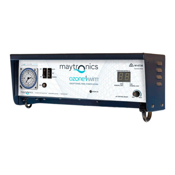
Control Unit Features 1200i unit Ozone Run Indicator Ozone Output Fuse Positive Cell Lead (Red) Master Switch Negative Cell Lead (Black) Air Filter Gas Sensor Connector (White) * 1200i does not have a chlorinator. The consumer needs an existing chlorinator. - Page 7 1000, 2000, 3000 units Ozone Run Indicator Air Filter Chlorine Cell Output Display Ozone Output Fuse pH Drive Socket (12V plug) Sanitation Switch Positive Cell Lead (Red) Master Switch Negative Cell Lead (Black) Chlorine Cell Output Control (0-99) Gas Sensor Connector (White) Push menu for e-Series - Dosage menu Timer (d0-d9 &...
-
Page 8: Installation
INSTALLATION... -
Page 9: Installation Guide
Installation Guide 1200i control units These products must be installed by a qualified installer CONTROL UNIT CHLORINATOR CELL MEDIA FILTER VENTURI from PUMP pool return to pool Note: Install the Ozone Swim control unit a minimum of 900mm above ground level in an area protected from the elements to eliminate possible damage from severe weather conditions. - Page 10 1000, 2000, 3000 control units These products must be installed by a qualified installer CONTROL UNIT CHLORINATOR CELL MEDIA FILTER VENTURI from PUMP pool return to pool Note: If this system is installed below water level, ensure you have a drain valve fitted to the ozone outlet.
- Page 11 Step 4: Connect the chlorine cell cable to the three colour coded terminals located on chlorine cell. (Terminals need to be slightly crimped for snug fit). Step 5: Ensure appropriate salt/mineral levels are achieved (3500 - 4500ppm) and dissolved. (Confirm with builder/supplier that chemicals can be added to the pool).
-
Page 12: Important Notes
Important Notes Chlorinator Cell Housing Installation The Ozone Swim cell housing must be plumbed into the return line of the pool filter system after the filter and any diversion valves. In situations where a heater is incorporated, the Ozone Swim cell housing must be installed after the heater. - Page 13 Pump Outlet Socket A 240 volt pump output power socket is supplied and located on the left- hand underside of the Ozone Swim control unit. Your pool pump power supply lead should be plugged into the socket so that when the time clock switches at the designated times both the Ozone Swim and the pump will activate in unison.
- Page 14 Flooded Installation* For installations where control box is below water level POOL from CHLORINATOR filter CELL CONTROL UNIT If water level is above the OzoneSwim control unit, a drain valve must be fitted. DRAIN VALVE VENTURI return to pool * Diagram is for illustration purposes only. Does not include all required swimming pool equipment. Installation with De-Gas Chamber* Ozone Swim control unit must be installed above water level,...
-
Page 15: Operations
OPERATIONS U s e r M a n U a l... -
Page 16: Operating Instructions
New Pools • It is essential that the new pool is balanced correctly. Consult your pool builder on how do this or Maytronics can provide information to do this. • You can find the water chemistry parameters on p. 21 of this manual. - Page 17 Sanitation Switch The system will not operate. Ozone Swim 1000, 2000 and 3000 series User Ma Auto The time clock will automatically switch your pool equipment on or off at your designated times. Manual The timer is by-passed, the system will operate all •...
- Page 18 Checking Chlorination Output The chlorine cell output controller regulates the amount of chlorine production relevant to the position it has been set to. By adjusting the cell output controller clockwise, you increase chlorine production and by turning anti clockwise you reduce production. Do not attempt to turn the controller beyond its stopping positions as this could cause damage to your unit that is not covered by warranty.
- Page 19 Chlorine Cell Output Display Definitions (1000, 2000 & 3000 series only) Your Ozone Swim unit is fitted with a digital display. During operation of your Ozone Swim unit the display will illuminate relevant to the degree at which the chlorine output control has been adjusted. You can increase or decrease chlorine output to suit your pool’s requirements.
-
Page 20: Maintenance
MAINTENANCE... -
Page 21: Maintenance
Maintenance Replace the check valve in the Ozone Every 12 months or as required The Teflon check valve prevents water from returning to the system. Flooded systems (below water level) require a water trap (drain valve) to protect the system in the event that the check valve fails. To replace the check valve simply pull the delivery line off the check valve at both ends and replace with new check valve. -
Page 22: Warranty
WARRANTY... -
Page 23: Warranty Information
• 5 year pro-rata warranty of chlorinator cell. (1000, 2000, 3000 Warranty series only). • 10 year (1 YEAR IN-FIELD) warranty on the ozone production corona discharge unit. Activate your Ozone Swim warranty by registering at: maytronics.com.au/support/registration Glass Tube 3 Year Warranty Ozone PCB 3 Year Warranty Stainless Tube... -
Page 24: Troubleshooting
TROUBLESHOOTING... -
Page 25: Troubleshooting
Troubleshooting Fault Potential Causes Action Required Cell output display flashing • Pump turned off or • Ensure pump is on disconnected “Pb” continuously (no water • Valves closed • Ensure correct valves are open flow) • Gas sensor wire at cell •... - Page 26 ozoneswim.com.au...
Need help?
Do you have a question about the Ozone Swim 1000 and is the answer not in the manual?
Questions and answers