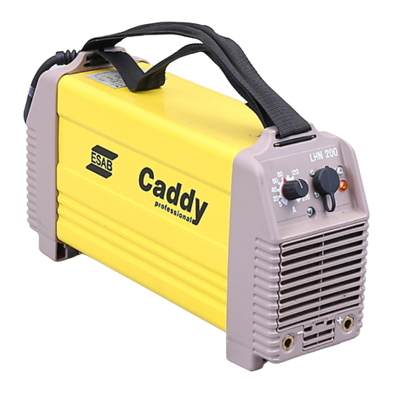
Summarization of Contents
Safety Warnings
Electric Shock Hazards
Dangers of electric shock during operation.
Fumes and Gases Health Risks
Health risks from welding fumes and gases.
Arc Ray Hazards
Eye and skin injury risks from arc rays.
Fire Hazard from Spatter
Risk of fire from welding sparks/spatter.
Noise Hazard
Hearing damage risk from excessive noise.
Malfunction Handling
Action to take in case of malfunction.
Static Electricity Risks
Risks to electronic components from static discharge.
Component Description
AP01 Main Circuit Board
Main circuit board with control electronics.
AP02 Positive Pole Board
Circuit board with power transistors for positive pole.
AP03 Negative Pole Board
Circuit board with power transistors for negative pole.
AP04 Transient Protection Board
Suppression circuit board for transient voltages.
AP05 EMC Suppression Board
Suppression circuit board for EMC.
Transient Protection Unit V03, V04
Explanation of transient protection circuit for V03, V04.
Component Positions AP01
AP01 Variant 0481 870 880
Component layout for AP01, before serial number 220-xxx-xxxx.
AP01 Variant 0481 870 885
Component layout for AP01, before serial number 220-xxx-xxxx.
AP01 Variant 0486 886 880
Component layout for AP01, from serial number 220-xxx-xxxx.
AP01 High Voltage Warning
Warning about high voltage in shaded areas of the circuit board.
Description of Operation AP01
Power Supply Circuit
Explanation of the power supply circuit for AP01.
Thermal Shutdown Circuit
Operation of the thermal shutdown circuit.
Under Voltage Detector Circuit
Circuit sensing low mains power supply voltage.
Current Detector Circuit
Circuit sensing welding current using inductor L01.
Open-Circuit Voltage Detector
Defines open-circuit and welding voltages.
Arc Voltage Limitation Circuit
Circuit limiting arc and open-circuit voltage.
Current Reference Circuit
Supplies signal to current setting potentiometer and remote control.
Control Amplifier Circuit
Sets welding current relative to current and arc voltage.
Pulse Width Modulator Circuit
Determines frequency and pulse time for MOSFET transistors.
Gate Circuit Operation
Driver stage for MOSFET transistors, providing gate pulses.
Circuit Diagram AP02
AP02 Variants and Description
Details variants (-880, -882, -889) and transistor replacement.
Circuit Diagram AP03
AP03 Variants and Description
Details variants (-880, -882, -889) and transistor replacement.
MOS Tester
Connection and Testing Procedure
Steps for connecting and testing the MOS tester.
Critical Tester Notes
Critical advice on replacing transistor boards and checking pulses.
Assembly and Disassembly
Rear Panel and Casing Removal
Steps to remove the rear panel and casing.
Front Panel Removal
Steps to remove the front panel and related parts.
Rectifier Unit Removal and Fitting
Procedures for removing and installing the rectifier unit.
Diode Module Fitting
Procedure for installing diode modules.
Transistor Board Removal and Refitting
Steps to remove and refit transistor boards.
AP03 Circuit Board Connections
Details connections for AP03 for different models.
Technical Data
Load Capacity Specifications
Specs for load capacity at different intermittencies.
Operating Range Specs
Stepless current ranges for each model.
Open-Circuit Voltage Specs
Open-circuit voltage specifications.
Mains Power Supply Details
Voltage, current, frequency, fuse rating.
Unit Weight
Weight of the units.
Outline Dimensions
Physical dimensions of models.
Installation
Caddy 130/140 Installation Guide
Installation details for 230V models.
Caddy 200 Installation Guide
Installation details for 400V model.
Welding Cable Requirements
Details welding cable cross-sections and length.
Operation
Front Panel Controls and Indicators
Description of front panel controls and indicators.
Coated Electrode Welding
Suitability for welding with coated electrodes.
TIG Welding Procedure
Suitability and requirements for TIG welding.
Welding Safety Precautions
General safety advice for welding operations.
Maintenance
Air Filter Maintenance
Procedure for cleaning and replacing the air filter.
Casing Cleaning Procedure
Steps for cleaning the machine casing.


Need help?
Do you have a question about the LHN 130 and is the answer not in the manual?
Questions and answers