
Related Manuals for ESAB LHF 405 PIPEWELD


Summary of Contents for ESAB LHF 405 PIPEWELD
- Page 1 LHF 405 PIPEWELD LHF 615 PIPEWELD Service manual 0349 300 070 071024 Valid for serial no. 422, 423- -xxx- -xxxx...
-
Page 2: Table Of Contents
..............WIRING DIAGRAM, LHF 405 PIPEWELD . -
Page 3: Read This First
This manual contains details of all design changes that have been made up to and including October 2007. The LHF 405 PIPEWELD and LHF 405 PIPEWELD are designed and tested in accordance with international and European standards IEC/EN 60974- -1 and IEC/EN 60974- -10. -
Page 4: Technical Data
TECHNICAL DATA LHF 405 PIPEWELD LHF 615 PIPEWELD Maximum load 35 % duty cycle 400 A/36 V 610 A/44 V 60 % duty cycle 310 A/33 V 450 A/38 V 100 % duty cycle 240 A/30 V 345 A/34 V... -
Page 5: Wiring Diagram, Lhf 405 Pipeweld
WIRING DIAGRAM, LHF 405 PIPEWELD Component description WARNING ! STATIC ELECTRICITY can damage circuit boards and electronic components. Observe precautions for handling electrostatic S S S S sensitive devices. Use proper static- -proof bags and boxes. S S S S Thermal switch: breaks at 68_C, resets at 59_C;... - Page 6 Freewheel diode V8,V9,V10, Base current diodes V11,V12,V13 Contact, 6 pole, male Remote control socket Mains terminal block Terminal block Terminal block Terminal block XF20 Contact, 15 pole, female XF30 Contact, 9 pole, female XF40 Contact, 12 pole, female XK1,XK2 Welding current terminals XM20 Contact, 15 pole, male XM30...
-
Page 7: Lhf 405 Pipeweld
LHF 405 PIPEWELD Edition 071024 - - 7 - - smlhfpw1... -
Page 8: Wiring Diagram, Lhf 615 Pipeweld
WIRING DIAGRAM, LHF 615 PIPEWELD Component description WARNING ! STATIC ELECTRICITY can damage circuit boards and electronic components. Observe precautions for handling electrostatic S S S S sensitive devices. Use proper static- -proof bags and boxes. S S S S Thermal switch: breaks at 68_C, resets at 59_C;... - Page 9 Freewheel diode V8,V9,V10, Base current diodes V11,V12,V13 Contact, 6 pole, male Remote control socket Mains terminal block Terminal block Terminal block Terminal block XF20 Contact, 15 pole, female XF30 Contact, 9 pole, female XF40 Contact, 12 pole, female XK1,XK2 Welding current terminals XM20 Contact, 15 pole, male XM30...
-
Page 10: Lhf 615 Pipeweld
LHF 615 PIPEWELD Edition 071024 - - 10 - - smlhfpw1... -
Page 11: Description Of Operation
DESCRIPTION OF OPERATION LH20/1 control board LH20/1:1 Current setting The bandgap reference 1,23V diode V2 on LH10/2 PCB makes up a primary voltage reference for current setting circuit and for digital meter. Current setting reference voltage 10,7V is derived from 1,23V by the amplifier made of A2a, V30, C14, R47, R46. -
Page 12: Lh20/1:2 Current And Voltage Meter
LH20/1:2 Current and voltage meter The meter is based upon typical application of ICL7107 integrated circuit. Reference voltage 1,23V is derived from diode V2. +5V supply consists of C30, VB1, C31, A10, C32, C33, while --5V supply consists of R1, V1, C34. Measurement of voltage/current is selected with switch Q4. -
Page 13: Lh20/1:3 Functional Control Circuit Antistick, Hotstart, Arcforce
LH20/1:3 Functional control circuit ANTISTICK, HOTSTART, ARCFORCE The ANTISTICK function is carried out by the circuit made of the A3 IC and the transistor V31. If the output voltage falls down below the ANTISTICK threshold, transistor V31 switches on, consequently switches off the output transistor of the A3b comparator and the output transistor of the A3a comparator switches on. -
Page 14: Lh20/1:4 Tig Mode Operation
LH20/1:4 TIG mode operation Tig mode is selected with switch S1 middle position. While TIG mode is active the ANTISTICK function is enabled, and HOT START and ARC FORCE functions are disabled. In TIG mode transistor V35 is open. Transistors V36, V37, V38 are also open untill trigger on welding torch is pressed. -
Page 15: Lh20/1:5 Wireless Remote Current Control Receiver
LH20/1:5 Wireless remote current control receiver D4 and D5 ICs form 8 bit memory counter for transmitted value of welding current. A8 and A9 ICs form D/A converter that converts binary current value to analog within range of 0--10,7V. Comparator A6a forms detector of signal transmitted by transmitter N02. -
Page 16: Lh20/1:6 Power Supply
LH20/1:6 Power supply Power supply is placed on LH20/1 board and consists of positive and negative voltage sources. Positive power supply. +24V supplies thyristor control circuitry; +15V supplies pulse circuitry on LH20/1 board and supplies function board LH10/2; +14,5V supplies regulator and current shunt amplifier. Negative power supply. -
Page 17: Lh20/1:8 Synchronisation And Thyristors Firing
LH20/1:8 Synchronisation and thyristors firing The synchronisation circuit consists of synchronised ramp generators, comparators, and firing pulse forming circuit. Signal from the synchronising winding goes via R66(53)(40) and diode limiter made V26(23)(20) and V27(24)(21) diodes, and then through divider R67(54)(41), R68(55)(42) to non--inverting input of the comparator A5b(A4b)(A3b). -
Page 18: Lh20/1:9 Thermal Overload Circuit
LH20/1:9 Thermal overload circuit The circuit co--operates with NC thermal switches connected in series. Opening of any of them (placed on the transfer or the rectifier) switches the V1 transistor on. Closed the V1 transistor switches on the H1 indication lamp and disables thyristors firing. -
Page 19: Lh20/1 -- Components Layout
LH20/1 - - Components layout Edition 071024 - - 19 - - smlhfpw1... -
Page 20: Lh10/2 -- Components Layout
LH10/2 - - Components layout Edition 071024 - - 20 - - smlhfpw1... -
Page 21: Checking And Calibration Procedures
R01 (Current Setting), potentiometers R02 (HOT START) and R03 (ARC FORCE) set to minimum, d. with multiturn potentiometer R6 set display value at: 400A (LHF 405 PIPEWELD) or at 610A (LHF 615 PIPEWELD), e. set min current value with potentiometer R01 (Current Setting), with potentiometer R29 set display value at 10A. - Page 22 400A@36V (LHF 405 PIPEWELD) or 610A@44V (LHF 615 PIPEWELD), e. check the setting of the following values of the output current: 10A@22V; 100A@24V; 200A@28V; 400A@36V (LHF 405 PIPEWELD) or 10A@22V; 200A@28V; 400A@36V; 610A@44V (LHF 615 PIPEWELD). HOT START checking. a. set 100A output current by means of the setting knob, b.
-
Page 23: Service Instructions
a. set switch S3 to “INT”, S1 to “TIG” and S2 to “SHORT”, b. connect pins (1) and (2) of socket X03 (press the trigger of connected to machine welding torch) and set current value to 100A, after releasing the trigger there should be initial current value for contact arc striking diplayed, load the source with 1Ohm + 0,24Ohm welding resitors -- no current should flow through the resistors as the trigger is released (output voltage = 0V),... -
Page 24: Thermal Switch (Thermostat) Replacement Procedure
Thermal switch (thermostat) replacement procedure Spare thermostat must be the same type as replaced one. Spare thermostat should be mounted within radius of 10mm or less from broken thermostat. If it’s possible and safe for transformer winding, broken thermostat may be removed. -
Page 25: Instructions
INSTRUCTIONS This chapter is an extract from the instructions for LHF 405 PIPEWELD, 615 PIPEWELD. SAFETY Users of ESAB welding equipment have the ultimate responsibility for ensuring that anyone who works on or near the equipment observes all the relevant safety precautions. Safety precautions must meet the requirements that apply to this type of welding equipment. -
Page 26: Installation
Connect the mains cable to the rectifier according to the relevant regulations and install a suitable fuse in the main fuse box. Make sure the welding rectifier is not covered or positioned so that cooling is obstructed. Connecting to mains LHF 405 PIPEWELD LHF 615 PIPEWELD Frequency 50 Hz 50 Hz... - Page 27 NB: The mains cable areas and fuse sizes as shown above are in accordance with Swedish regulations. They may not be applicable in other countries: make sure that the cable area and fuse sizes comply with the relevant national regulations. Edition 071024 - - 27 - - smlhfpw2...
-
Page 28: Assembly Of Components
Assembly of components Edition 071024 - - 28 - - smlhfpw2... -
Page 29: Operation
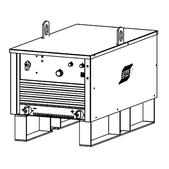
OPERATION Select suitable earth and return cables and connect them to the terminals marked + and -- on the front of the rectifier. Connect the return cable to the work piece. Set switch (1) to position ”I”. The display (4) will light and the fan will start. Select the welding method using the switch (6). -
Page 30: Mma Welding
1. Mains supply switch 2. Yellow lamp, thermal cut--out 3. Switch for display selection -- Volt. or Amp 4. Digital display for welding parameters 5. Arc lenght switch, long/short 6. Method selector switch: Arc Air Gouging, MMA, TIG 7. Remote switch 8. -
Page 31: Maintenance
After cleaning, all safety plates must be mounted before you connect the power source to the mains supply. ORDERING OF SPARE PARTS Spare parts may be ordered through your nearest ESAB dealer, see the last page of this publication. Edition 071024... -
Page 32: Notes
NOTES - - 32 - - notes... - Page 33 - - 33 - - notes...
- Page 34 ESAB subsidiaries and representative offices Europe Asia/Pacific Representative offices NORWAY AS ESAB AUSTRIA BULGARIA CHINA Larvik ESAB Ges.m.b.H ESAB Representative Office Shanghai ESAB A/P Tel: +47 33 12 10 00 Vienna- -Liesing Sofia Shanghai Fax: +47 33 11 52 03...
Need help?
Do you have a question about the LHF 405 PIPEWELD and is the answer not in the manual?
Questions and answers