Table of Contents
Advertisement
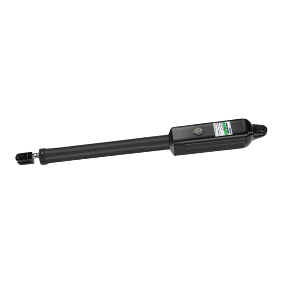
Single Swing Gate Opener
★ Please read and follow all warnings, precautions and instructions before
installation and use.
★ Coming with UPS01 uninterrupted power supply, this series gate opener can be
powered by AC 100-240V electricity directly. It is allowed to use additional battery
(NOT incl.) and solar panel (optional) as BACK-UP or MAIN power source with
this UPS01.
★ Never connect the solar panel to the control board directly to charge the battery.
★ Periodic checks of the opener are required to ensure safe operation.
★ Save this manual.
C030568
User's Manual
Model:
A3131/A5131/A8131
A3131S/A5131S/A8131S
TOPENS Website
www.topens.com
Email: support@topens.com
VER 22c
Advertisement
Table of Contents

Related Manuals for Topens A8131


Summary of Contents for Topens A8131
- Page 1 Single Swing Gate Opener User’s Manual Model: A3131/A5131/A8131 A3131S/A5131S/A8131S TOPENS Website www.topens.com Email: support@topens.com ★ Please read and follow all warnings, precautions and instructions before installation and use. ★ Coming with UPS01 uninterrupted power supply, this series gate opener can be powered by AC 100-240V electricity directly.
- Page 2 Visit: www.topens.com Please record the product model, your email address etc. in the spaces provided below. Refer to this list when contacting TOPENS for technical service or assistance with your automatic gate opener. Where did you purchase? (Amazon.com; Amazon.ca: Amazon.co.uk, Amazon.de; Other, Please...
-
Page 3: Table Of Contents
A3131 Parts List ..............................3 A5131 / A8131 Parts List ........................... 4 Extra Parts for A3131/ 5131/ 8131 S ......................... 5 Accessories Parts (Included in some models, refers to the actual package) ...........5 Optional Accessories Parts List (Available at TOPENS Store) .................5 Replacement Parts ............................6... -
Page 4: Safety Installation Information
use on any pedestrian gate. Pedestrians must be Safety Installation Information supplied with a separate pedestrian access. 1. READ and FOLLOW all instruction. For an installation utilizing non-contact sensors The gate opener is intended for use with Class I (safety sensors), see product manual on vehicular swing gates. - Page 5 BEFORE digging. NOTE: TOPENS Gate Operator can be used for driveway gates made by steel, wood, vinyl, and shaped as panel, tube, and chain-link. While use on solid surface gates is NOT recommended. Solid surface gates have a high...
-
Page 6: A3131 Parts List
A3131 Parts List... -
Page 7: A5131 / A8131 Parts List
A5131 / A8131 Parts List... -
Page 8: Extra Parts For A3131/ 5131/ 8131 S
Extra Parts for A3131/ 5131/ 8131 S Accessories Parts (Included in some models, refers to the actual package) Optional Accessories Parts List (Available at TOPENS Store) TC186-R WiFi TC188 Universal ERM12 External M12 Remote Control Smartphone Remote Wireless and Wired... -
Page 9: Replacement Parts
A3131S Gate Opener A8131S Gate Opener UPS01 Uninterrupted MK01 Hardware Kit Power Supply WARNING: Changes or modifications not expressly specified by this user manual, TOPENS could void the warranty of this equipment. Tools Needed: ·Power Drill ·Tape Measure ·Open End Wrenches - 14# &17# or Adjustable Wrenches ·Wire Strippers... - Page 10 Actuator speed: 16mm/s(0.6 in/s) Max. actuator travel: 385mm(15.2 in) Ambient Temperature: -20℃~ +50℃ (0°F to 120°F) Protection class: IP44 NOTE: “NR" indicates this size and weight combination recommended for one arm actuator. NOTE: Ball bearing hinges should be used on all gates weighing over 140kg (300 lbs).
-
Page 11: Installation Overview
Installation Overview Preparation for Installation There are two installation types for the gate opener, Pull-to-Open and Push-to-Open. In the Push-to-Open installation, gate opens out from the property. A Push-To-Open Bracket (PSO part) is required to be used for each gate. NOTE: Ensure the gate does not open into public areas. -
Page 12: Install The Opener On The Gate - For Pull To Open
Install the Opener on the Gate – for Pull to Open The position of Post Bracket is very important. The following illustrations and tables are required to determine the proper mounting position for the Post Bracket. The tables show the maximum opening angle of the gate for a given A and B. - Page 13 2. Attach the gate bracket and post bracket assy. to the opener by inserting a clevis pin. Secure the clevis pins using the hairpin clips. 3. Open the release hole plug on the top of the gate opener, insert the release key, and turn the key 90°...
- Page 14 5. Make sure that there is a minimum clearance of 2.5cm between the gate and the opener and that the opener and the Post Pivot Bracket are not binding in both the gate-open and gate-closed positions. If there is not at least 2.5cm of clearance or if the opener and the Post Pivot Bracket are binding, rotate the Post Pivot Bracket and/or move the Post Bracket Assy.
- Page 15 the opener and brackets assy. by taking off the C-clamps. 7. Drill 10.5 mm diameter holes through the post and the gate at the marked locations. 8. Attach the post bracket assemblies to the gate post by inserting M10 x 200 bolts through each post bracket assy.
-
Page 16: Install The Opener On The Gate - For Push To Open
12. Open the release hole plug on the top of the gate opener, insert the release key, and turn the key 90° counterclockwise. This restores normal operation. NOTE: The setting of the PULL/PUSH TO OPEN of the control board should be in accordance with the installation. - Page 17 1. Insert the bolts through the holes of post bracket and PSO part (push to open bracket) as shown. Place washers and nuts on the bottom of the bolts and hand tighten. 2. Attach the gate bracket and post bracket assy. to the opener by inserting a clevis pin. Secure the clevis pins using the hairpin clips.
- Page 18 5. Make sure that there is a minimum clearance of 2.5cm between the gate and the opener and that the opener and the PSO part are not binding in both the gate-open and gate-closed positions. If there is not at least 2.5cm of clearance or if the opener and the PSO part are binding, rotate the PSO part and/or move the Post Bracket Assy.
- Page 19 6. Sign the bolt-hole point on the gate post and gate. Do this by placing a punch or a sign in the middle of each bolt slot on the post bracket and the gate bracket. It allows slight adjustments to the post bracket.
- Page 20 10. Cut off any part of the bolts that extend beyond the tightened nuts. 11. With the opener fully retracted and with the gate in the fully close position (for Push-to-Open installation), insert a clevis pin through the gate opener and the PSO part and insert another clevis pin through the gate opener and the Gate Bracket.
-
Page 21: Mounting Of The Control Box
12. Open the release hole plug on the top of the gate opener, insert the release key, and turn the key 90° counterclockwise. This restores normal operation. NOTE: The setting of the PULL/PUSH TO OPEN of the control board should be in accordance with the installation. -
Page 22: Connection Of The Power Supply
Connection of the Power Supply A 24VDC AC-DC power supply is included in the kit. You can plug it to the AC socket to use it power up the gate opener directly if the AC electricity is accessible. You can also connect a 24VDC back-up battery (2*12VDC, connected in series to become 24VDC) to the power supply if the AC electricity is not stable. - Page 23 the control box refer to step 1 in this chapter. And then you can connect 2 PCS 12VDC batteries in series and then connect it to the UPS-01 power supply. Power Mode 3. Use the batteries as the power source, only use the solar panel to charge the batteries If the AC electricity is not available, then you can choose the batteries as the power source and use the solar panel to charge the batteries.
- Page 24 Power Mode 4. By AC electricity and back-up batteries, use the AC electricity and the solar panel to charge the batteries at the same time If you want to use the solar panel and the AC electricity to charge the batteries at the same time, firstly you can connect the UPS-01 power supply &...
-
Page 25: Connection Of The Control Board
Connection of the Control Board 1. Actuator Insert the stripped cable wires into the appropriate terminals on the opener terminals block. The red wire should be inserted into the “+MOTOR” terminal(#17), the black wire into “MOTOR-” terminal (#18), the blue wire into “DLMT”... - Page 26 Before connecting this item, please refer to the chapter of “Connection of the Power Supply”. 3. Battery (not included) & Solar panel (Optional, ONLY included in A3131/ A5131/ A8131 S) Please connect them following the chapter of “Connection of the Power Supply”.
-
Page 27: How To Program The Remote To The Opener
11. Wired Keypad (24VDC) (optional) The RED wire of the wired keypad should be connected into the “BAT+” (#11) terminal. The BLACK wire of the wired keypad should be connected into the “COM” (#5) terminal. The PURPLE wire of the wired keypad should be connected into the “COM” (#5) terminal. The BLUE wire of the wired keypad should be connected into the “O/S/C”... -
Page 28: How To Erase All The Remote Codes
Each remote has four buttons, from top to bottom are separately A, B, C and D. You may use this remote to operate as many as 4 sets TOPENS swing gate openers or 1 set TOPENS sliding gate opener and 2 sets TOPENS swing gate openers. -
Page 29: Adjusting The Limit Switch
the default password “888888” to operate the opener after programming. You can press “PIN” “8 8 8 8 8 8” and then press “OK” to confirm to operate the opener. Also you can change the password of the keypad follow the below steps. Press “PIN” and then input the six digits old password and then press ”PIN”... -
Page 30: Setting Of The Control Board
If the arm opens over the desired open position, press the remote control to stop the opener. Use a screwdriver to loosen the screw of the limit B, slightly slide the limit switch B inwards. If the arm opens halfway and fails to get to the desired open position, slightly slide the limit switch B outwards. Please repeat the above steps, until the arm could arrive and automatically stop at the desired open position. -
Page 31: Maintenance
opener. Factory default setting is OFF 2. Potentiometers There are 3 potentiometers located in the control board. They are used to adjust the stall force, auto-close time and soft stop period. Potentiometer A is used to adjust the stall force the gate opener. Turn the potentiometer clockwise to increase the stall force, and turn it counter-clockwise to decrease the stall force. -
Page 32: Trouble Shooting
Trouble Shooting Have a multi-meter to check voltage and continuity. Use caution when checking high voltage terminals. Symptom Possible Solution(s) 1. Make sure the connection between the UPS01 and control box is correct and fastening. 2. Make sure the UPS01 power supply has been plugged into the AC main socket or the batteries (2*12V batteries connected in series) have been connected to the The opener does not UPS01 well. - Page 33 Gate automatically 1. Setting of DIP switch #1 would be wrong. Please set the dip switch correctly opens, but does not according to the push/pull to opener installation of the gate opener. automatically close...
- Page 36 Your comments and suggestions are important to us as they help us provide the best possible service. Should you have any need to contact us, the info below will help you get in touch: TOPENS Website www.topens.com Contact Us: E-mail: support@topens.com Kindly include your Product Model, Purchasing Date &...
Need help?
Do you have a question about the A8131 and is the answer not in the manual?
Questions and answers