Table of Contents
Advertisement
Advertisement
Table of Contents
Troubleshooting

Related Manuals for Stairmaster FreeClimber 4400 PT


Summary of Contents for Stairmaster FreeClimber 4400 PT
- Page 1 FreeClimber Systems ® Owner’s Manual...
- Page 2 P/N 22569-E © 1997 StairMaster Sports/Medical Products, Inc., StairMaster and FreeClimber are registered trademarks or trademarks of StairMaster Sports/Medical Products, Inc. in the United States and /or other countries. All other trademarks are trademarks of their respective companies. Page iii...
- Page 3 The StairMaster name on your equipment reinforces your club's reputa- tion for quality and effectiveness. NATIONAL SALES SUPPORT StairMaster is one of the few organizations that maintains its own fully staffed national sales organization. These individuals will bend over backwards to make sure you are satisfied.
- Page 4 For total-body conditioning, club members will love the fact they can ® Other StairMaster stairclimbers use the handles on the StairMaster ® include the Stepmill 7000 PT – for the FreeRunner 5400 for an effective most challenging stairclimbing upper-body workout.
- Page 5 ® selected the Quinton treadmill as a that StairMaster is famous for, but are new addition to our product line – with designed with such uncompromising four different models to choose from – attention to every biomechanical ®...
- Page 6 Crossrobics products Club members will feel the difference are innovative machines that combine ® the first time they use StairMaster aerobic exercise with a weight stack strength equipment – designed to for strength conditioning. Available work the way your body works.
- Page 7 WARRANTY This is to certify that the StairMaster ® FreeClimber ® exercise system is warranted by StairMaster Sports/Medical Products, Inc. to be free of all defects in materials and workmanship. This warranty does not apply to any defect caused by negligence, misuse, accident, alteration, improper maintenance, or an “act of God”.
- Page 8 The StairMaster FreeClimber exercise systems are vertical climbing machines with an independent step action. The independent step action, combined with the patented pedal geometry featured on all StairMaster steppers, provides an aerobic workout equivalent to uphill running or climbing stairs, but without the high-impact pounding to the joints and muscles.
-
Page 9: Table Of Contents
CONTENTS SAFFETY GUIDELINES ..................1 INTRODUCTION ....................3 INSTALLATION INSTRUCTIONS ................ 6 BASIC OPERATING INSTRUCTIONS ..............9 General Guidelines for Safe Operation ............9 Your First Workout..................10 The ATTRACT Mode ................10 Basic Instructions for First-Time Users ..........10 4600/4400 PT/CL Console Set-Up ............ - Page 10 CONTENTS FREECLIMBER 4200 PT CONSOLE ..............28 Top Window ....................28 Workout Setup ..................28 Timer ...................... 30 Bottom Window .................... 30 Keypad ....................31 Quick Start Option ..................31 MAINTENANCE INSTRUCTIONS ..............32 Helpful Hints....................32 Tool List ......................32 Maintenance Records ...................
- Page 11 CONTENTS Mechanical Troubleshooting ................. 45 PARTS REMOVAL AND REPLACEMENT ............48 Covers ......................48 Mid Cover ....................48 Top Cover ....................48 Shield (4600 PT/CL ) ................49 Bottom Cover ..................49 Console ......................50 Console Adjustment (4600 PT/CL) ..............50 Poly-V and HTD Belt ..................
- Page 12 CONTENTS LIST OF TABLES Table 1. Dimensions and Specifications for the ® ® StairMaster FreeClimber Exercise Systems ........5 Table 2. Fitness Rating Norms (METs) ............20 Table 3: Character Codes for the Scrolling Message ........25 Table 4. Console Codes ................. 27 Table 5.
-
Page 13: Saffety Guidelines
SAFETY GUIDELINES HEN USING ELECTRICAL EQUIPMENT ALWAYS FOLLOW THESE BASIC PRECAUTIONS IMPORTANT SAFETY INSTRUCTIONS This symbol appearing throughout this manual means Attention! Be Alert! Your safety is involved. The following definitions apply to the words “Danger” and “Warning” found throughout this manual: DANGER - Used to call attention to IMMEDIATE hazards which, if not avoided, will result in immediate, serious personal injury or loss of life. - Page 14 Use this machine only for its intended use as described in this Manual. Do not use parts, attachments, or accessories other than those provided by StairMaster ® Sports/Medical Products, Inc. Do not use the external power supply if it has a damaged cord or plug, if it is not working properly, if it has been dropped or damaged, or dropped into water.
-
Page 15: Introduction
INTRODUCTION Before leaving the manufacturing facility in Tulsa, Oklahoma, your StairMaster ® ® FreeClimber exercise system was thoroughly inspected and tested to ensure proper operation. The major parts of the machine are shown in Figures 1 and 2. Figure 1: Major Parts - 4600 PT/CL... -
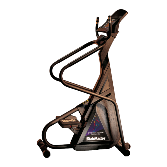
Page 16: Figure 2: Major Parts - 4400 Pt/Cl
INTRODUCTION Figure 2: Major Parts - 4400 PT/CL Page 4... -
Page 17: Table 1. Dimensions And Specifications For The ® Exercise Systems
For example, the console is located on the front of the machine. The dimensions and general specifications of the machines are listed in Table 1. Table 1. Dimensions and Specifications for the StairMaster ® FreeClimber ®... -
Page 18: Installation Instructions
INSTALLATION INSTRUCTIONS Assemble your machine before use. Machines shipped outside the United States need to be uncrated before they can be assembled; refer to the “Uncrating Instructions” included with your machine for the details. Remove all shipping material from your machine once it is in place. Make sure the machine is level before you use it for the first time. -
Page 19: Figure 4: Dc Power Connector
INSTALLATION INSTRUCTIONS If you have a 4600/4400 CL, skip to step 9. If you have a 4600/4400/ 4200 PT, connect the DC cable of the power supply to the connector near the bottom of the left side cover (see Figure 4). Figure 4: DC Power Connector Place the power supply on the floor near an AC wall outlet. - Page 20 INSTALLATION INSTRUCTIONS Check to be sure that the input AC power rating marked on the power supply matches the available power. If it does not, obtain the matching power supply from StairMaster ® Sports/Medical Products, Inc. before proceeding any further.
-
Page 21: Basic Operating Instructions
® Although all equipment manufactured by StairMaster Sports/Medical Products, Inc. has been thoroughly inspected by the manufacturing facility prior to shipment, proper installation and regular maintenance are required to ensure safety. -
Page 22: Your First Workout
EXERCISE SYSTEM The ATTRACT Mode All workouts on the StairMaster FreeClimber exercise system start from the ATTRACT mode. The 4600/4400 PT/CL console displays an EKG signal or scrolls a message in the text bar when it is in the ATTRACT mode. You must step on the 4600/4400 CL pedals before the console goes into the ATTRACT mode. -
Page 23: 4200 Pt Console Set-Up
BASIC OPERATING INSTRUCTIONS The console will prompt you to enter your body weight. Enter your weight in pounds (or kilograms if the console is set up for metric units). Correct entry errors by pressing [CLEAR] before you press [ENTER]. The console will prompt you to enter the workout time in one minute increments between five and 60 minutes. -
Page 24: Figure 5: Correct Exercise Posture
BASIC OPERATING INSTRUCTIONS Select an intensity level that allows you to stay in the middle of the pedal range of motion. Faster is not always better. Exercise at a level that is consistent with your fitness level. 4600/4400 PT: You can stop and rest as many times as necessary for up to two minutes at each rest period during all programs except the Constant Heart Rate program, which has unlimited fifteen second rest periods. -
Page 25: Contact Heart Rate (4600 Pt/Cl Only)
CONTACT HEART RATE (4600 PT/CL) The StairMaster ® FreeClimber ® features a digitized contact heart rate monitoring system. Through the use of stainless steel sensors built into the upper handles and sophisticated software, heart rate can be checked at any time during a workout. -
Page 26: Polar ® Heart Rate (4600/4400 Pt/Cl Only)
® POLAR HEART RATE (4600/4400 PT/CL ONLY) The StairMaster ® FreeClimber ® 4600/4400 PT/CL features Polar ® heart rate monitoring. The system consists of the receiver, located on the stepper, and a transmitter belt (purchased separately), worn across your chest. The transmitter belt senses the heart beat and sends a signal to the receiver. -
Page 27: Freeclimber 4600/4400 Pt/Cl Console
FREECLIMBER 4600/4400 PT/CL CONSOLE The StairMaster ® FreeClimber ® 4600/4400 PT/CL console is divided into four sections: the text bar, display, the function keypad, and the exercise program keypad (see Figures 6 &7). Figure 6: 4600 PT/CL Console Diagram Figure 7: 4400 PT/CL Console Diagram... -
Page 28: Text Bar
FREECLIMBER 4600/4400 PT/CL CONSOLE TEXT BAR Information regarding workout statistics and data entry is displayed or scrolled across the text bar. A countdown timer is located directly above the words "Interval Time". The timer shows the number of seconds remaining in the current interval. - Page 29 FREECLIMBER 4600/4400 PT/CL CONSOLE Intensity Level. Shows the current level between 1 (the easiest) and 20 (the hardest). Shows the number of lights in the Manual program between 1 and 14. METs. Gives you the relative energy cost of exercise. MET stands for multiples of the resting metabolic rate.
-
Page 30: Entertainment Keypad (4600 Pt/Cl)
FREECLIMBER 4600/4400 PT/CL CONSOLE Stop. If pressed at any time, the console will return to the ATTRACT mode. Workout Stats. If pressed during your workout, all workout statistics continuously scroll across the text bar. Press any key to stop scrolling at that statistic. -
Page 31: The Quick Start Option
FREECLIMBER 4600/4400 PT/CL CONSOLE After the profile is scrolled, the prompts are: • “PRESS ENTER KEY TO ACCEPT” • “ENTER BODY WEIGHT” -- type in your body weight in pounds (or kilograms if your console is set to metric units). •... -
Page 32: Table 2. Fitness Rating Norms (Mets)
FREECLIMBER 4600/4400 PT/CL CONSOLE Note: Keep stepping until the end of the Fit Test. The Fit Test will end if you stop stepping. The console will prompt you to find your pulse; use the artery below your thumb in your wrist or the artery in the side of your neck. Start counting the beats when the console prompts you—the first beat you feel is zero and then one and so on. -
Page 33: Preset Exercise Programs
FREECLIMBER 4600/4400 PT/CL CONSOLE Preset Exercise Programs 4600 PT/CL: There are four preset exercise programs. The exercise speed during the programs varies automatically over 14 increments within each of the 20 different intensity levels. Varying the intensity of an exercise program does not change the profile shown on the display. -
Page 34: The Jackpot Option
The jackpot option ® remains in effect until disabled by entering zero odds. StairMaster assumes no liability stemming from the use of the jackpot option. Laws or ordinances in your area may govern the use of this option. -
Page 35: Turning The Jackpot Option On And Off
FREECLIMBER 4600/4400 PT/CL CONSOLE Turning the Jackpot Option On and Off The computer must be in the ATTRACT mode. Press [INCREASE], [7707], [ENTER]. The prompt “ENTER ODDS” will appear in the console display. Enter the numeric odds you have selected, between 1 and 999. The jackpot results are saved in the console memory until the next workout is started. -
Page 36: Using A Custom Program
FREECLIMBER 4600/4400 PT/CL CONSOLE taller or shorter. Press [ENTER] to move one column to the right and [CLEAR] to move one column to the left. When all of the intervals are correctly programmed, press [0- 4600 PT/CL] or [YES - 4400 PT/CL] to save the profile. Press [STOP - 4600 PT/CL] or [START/STOP - 4400 PT/CL] to abort the programming process without saving the profile. -
Page 37: Editing The Scrolling Message
FREECLIMBER 4600/4400 PT/CL CONSOLE Table 3: Character Codes for the Scrolling Message r e t r e t r e t Í À Î È Â Ç Ê ¿ Ä ´ Ü Ö ß Å Á Ó É Ñ EDITING THE SCROLLING MESSAGE While the console is in the ATTRACT mode, press [+ INCREASE], [7], [6], [0], [7], [ENTER] to display the first character of the message onto the text bar. -
Page 38: Changing The Console Units And Language
FREECLIMBER 4600/4400 PT/CL CONSOLE To edit multiple characters at one time, press [9], [9], [ENTER] to erase all of the characters to the right of the last character displayed on the text bar. To erase the entire message, press [+ INCREASE], [1], [0], [5], [ENTER] while in the ATTRACT mode. -
Page 39: Table 4. Console Codes
FREECLIMBER 4600/4400 PT/CL CONSOLE Table 4. Console Codes i t c i l l a v i c i t p s i y a l i s i t r a i l l i l l i t p i l l n i t i t c... -
Page 40: Freeclimber 4200 Pt Console
FREECLIMBER 4200 PT CONSOLE The StairMaster ® FreeClimber ® 4200 PT console is divided into two LCD display windows. There is a four-function keypad located below the bottom window (see Figure 8). While you are exercising, the bottom window scrolls through a display of four workout statistics. - Page 41 FREECLIMBER 4200 PT CONSOLE The arrow pointing to the word "Program" should be flashing and "P1" should be displayed. P1 corresponds to the MANUAL program. Use the [+ or - ARROW] to change the workout option. "P2" corresponds to Steady Pace, "P3" to Fat Burner, and "P4" to Aerobic Training. The different workout option profiles are shown on the right side of the console.
-
Page 42: Timer
FREECLIMBER 4200 PT CONSOLE Timer During your workout, the top window keeps track of your workout time in min- utes and seconds. The display arrow points to the word "Time" on the console. You may rest for up to 30 seconds at any time during your workout. Either stop stepping or press [START/STOP] to begin your rest period. -
Page 43: Keypad
FREECLIMBER 4200 PT CONSOLE Keypad ENTER/SELECT. During workout setup, press this key to enter your personal information and then move to the next entry. During your workout, press this key to lock the bottom display window on any one statistic or to return to the scrolling mode. + or - ARROWS. -
Page 44: Maintenance Instructions
MAINTENANCE INSTRUCTIONS HELPFUL HINTS Read all maintenance instructions thoroughly before beginning work. In some cases, an assistant is required to perform the necessary tasks. All references to the right or left side and to the front or back are made as if you were on the machine ready to exercise. For example, the console is located on the front of the machine. -
Page 45: Initial Service
MAINTENANCE INSTRUCTIONS The 4200 PT console keeps track of the number of hours the machine was used and the total number of floors climbed. From the ATTRACT mode, press [+ ARROW] and then double-click [RESET]. The hours are shown in the top LCD window and the total floors are shown in the bottom LCD window. -
Page 46: Lubrication
Remove the bottom cover to get to the components. Place a protective mat on the floor while you lubricate your machine. A ® rubber floor mat is available from StairMaster Sports/Medical Products, Inc. Lubricate the drive chain and the step chains weekly. Try to penetrate the entire length of the chains with 30W motor oil. -
Page 47: Battery Charge
MAINTENANCE INSTRUCTIONS shafts with a dry cloth. Protect the shafts from corrosion with a thin coat of multi-purpose grease before reassembling. Remove the pedals every three months. Clean the pedal shaft and leveling arm pin with a dry cloth. Protect the pedal shaft and leveling arm pin from corrosion with a light coat of multi-purpose grease before reassembling. -
Page 48: Table 5. Recommended Preventive Maintenance Schedule
MAINTENANCE INSTRUCTIONS Table 5. Recommended Preventive Maintenance Schedule y l i r e t t u l y l i s n i e l c r o t a c i r e t l i o e v i s n i , e v e l c... -
Page 49: Troubleshooting
TROUBLESHOOTING GENERAL TROUBLESHOOTING GUIDELINES This troubleshooting section is organized into three basic problem sections: electrical troubleshooting, console diagnostics, and mechanical troubleshooting. Once you have identified the problem section, perform all the tests in the same order as written. To order a replacement part or for help with troubleshooting, contact our Customer Service Department. -
Page 50: Alternator Test
ELECTRICAL TROUBLESHOOTING Follow the white power connector wire to the where it plugs into the main cable white wire, and disconnect it from the main cable white wire. Set your voltmeter to VDC. Connect the positive lead of your voltmeter to the white wire from the power connector and touch the gray casing of the alternator with the negative lead of your voltmeter. -
Page 51: Diode Test
ELECTRICAL TROUBLESHOOTING Diode Test Remove the brown wire and diode from the field terminal of the alternator and set your voltmeter to the Ohms setting. Place one lead from the voltmeter on each end of the diode, and then reverse the leads. A diode that is good will show a high reading in one direction and a low reading when the leads are reversed. -
Page 52: Alternator Test
ELECTRICAL TROUBLESHOOTING Alternator Test Perform the Positive Output to Field test on the alternator: • Unplug the battery from the power control board • Remove the black wire from the B+ terminal on the alternator • Remove the brown wire from the field terminal on the alternator •... -
Page 53: 4600/4400 Pt/Cl Console Diagnostics
4600/4400 PT/CL CONSOLE DIAGNOSTIC TESTS The following tests are performed while the console is in the DIAGNOSTIC mode. While the console is in the ATTRACT mode, and without stepping on the pedals, press [+INCREASE], [1], [0], [7], [ENTER] to activate the DIAGNOSTIC mode. The numbers will not appear on the display as you enter them. -
Page 54: Speed Test
4600/4400 PT/CL CONSOLE DIAGNOSTIC TESTS keypad or the function keypad will light an LED within the outline on the display that corresponds to that button's position on the console. Firmly press each button. If the LED corresponding to the button you pushed does not light up, the keypad is bad and the console should be replaced. -
Page 55: Contact Heart Rate Test
4600/4400 PT/CL CONSOLE DIAGNOSTIC TESTS Contact Heart Rate Test (4600/4400 PT/CL only) The contact heart rate system is made up of the console and the contact heart rate handles. You can test each component by performing the following steps: While the console is in the ATTRACT mode (noted by a simulated EKG signal in the console display), or at the “SELECT A WORKOUT”... - Page 56 4600/4400 PT/CL CONSOLE DIAGNOSTIC TESTS While the console is in the ATTRACT mode (noted by a simulated EKG signal in the console display), or at the “SELECT A WORKOUT” prompt, press [+INCREASE], [1], [0], [8], [ENTER]. A flashing ♥ should be displayed in the console text bar. Your heart rate, in beats per minute, will show next to the heart icon.
-
Page 57: Mechanical Troubleshooting
MECHANICAL TROUBLESHOOTING If you hear a grinding or clicking noise, or experience excessive vibration during exercise, or if the pedals are not functioning properly, you probably have a prob- lem in the drive train. Attempt to isolate the problem area by performing the fol- lowing tests in precisely the order listed below. - Page 58 MECHANICAL TROUBLESHOOTING Remove the drive and step chains. Check the condition of the chains by flexing each link up and down. Each link should move freely. Replace the chain if any stiff or inflexible links are found or if the chain is rusty, corroded or otherwise damaged.
- Page 59 MECHANICAL TROUBLESHOOTING Remove the HTD belt. Inspect the belt, the Poly-V pulley and the HTD pulley for excessive wear. Replace if necessary. The Poly-V pulley should spin freely. If it does not, replace the eccentric shaft assembly. Inspect the HTD pulley for excessive wear and smoothness of operation.
-
Page 60: Parts Removal And Replacement
PARTS REMOVAL AND REPLACEMENT COVERS WARNING TO REDUCE THE RISK OF INJURY, DO NOT OPERATE THE MACHINE WHILE THE COVERS ARE REMOVED. DO NOT DEPRESS OR RAISE THE PEDALS WHILE ANYONE'S HANDS ARE INSIDE THE MACHINE. There are three covers on the 4400 PT/CL and the 4200 PT: the top cover, the mid cover and the bottom cover. -
Page 61: Shield (4600 Pt/Cl )
PARTS REMOVAL AND REPLACEMENT 4600 PT/CL: Use the fastener removal tool to release the cover fasteners and separate the top covers. To reinstall the 4400 PT/CL and 4200 PT fasteners, remove the pin completely from the base. Insert the base into the hole in the covers. Insert the pin into the base until it is flush with the base. -
Page 62: Console
PARTS REMOVAL AND REPLACEMENT CONSOLE Remove the four mounting knobs from the back of the console. Disconnect the main cable, contact heart rate cables (4600 PT/CL), and ® Polar cable (4600/4400 PT/CL) from the back of the console. Lift the console off the machine. Reverse the steps to reinstall the console. -
Page 63: Step Chain Retainer
PARTS REMOVAL AND REPLACEMENT Adjust the HTD belt tension so that you have 1/4 inch (0.6 cm) of side- to-side play with fingertip pressure (see Figure 30). The bottom shaft is mounted in an eccentric hub. To adjust the tension: •... -
Page 64: Step Chain
PARTS REMOVAL AND REPLACEMENT Check to ensure that the spring pulley turns freely and is not worn excessively. Refer to the “Spring Pulley” section if you have to replace the pulley. To reinstall the spring, connect it to the end of the step chain using the master link. -
Page 65: Spring Pulley
PARTS REMOVAL AND REPLACEMENT SPRING PULLEY Remove the bottom cover. Unhook the pedal arm return spring from the spring hanger. Remove the snap ring from the pulley shaft (see Figure 10). WARNING TO REDUCE THE RISK OF EYE INJURY, WEAR EYE PROTECTION WHEN REMOVING SNAP RINGS. -
Page 66: Drive Shaft Assembly
PARTS REMOVAL AND REPLACEMENT Remove the master link from the drive chain. Remove the drive chain from the sprockets. Reinstall the drive chain, ensuring the master link is properly installed. Check the drive chain tension. There should be a total of 1 to 1-1/2"... - Page 67 PARTS REMOVAL AND REPLACEMENT Remove the drive chain. Remove the sprocket and the other small parts from the left side of the hub assembly (see Figure 21). Slide the drive shaft to the right, out of the hub assembly. If you remove the right-hand clutch sprocket from the drive shaft, do not confuse it with the left-hand clutch sprocket.
-
Page 68: Pedal
PARTS REMOVAL AND REPLACEMENT PEDAL Remove the snap ring and flat washer from the leveling arm pin and the pedal shaft (see Figure 20). WARNING TO REDUCE THE RISK OF EYE INJURY, WEAR EYE PROTECTION WHEN REMOVING SNAP RINGS. Slide the pedal off the shaft. Clean the pedal shaft and leveling arm pin with a dry cloth. -
Page 69: Pedal Arm
PARTS REMOVAL AND REPLACEMENT PEDAL ARM Remove the pedal and the bottom cover. Remove the step chain retainers. Support the pedal arm. Unhook the pedal arm return spring from the spring hanger. Lift the step chain up and off the clutch sprocket and lower the pedal arm to the floor. -
Page 70: Eccentric Hub Assembly
PARTS REMOVAL AND REPLACEMENT ECCENTRIC HUB ASSEMBLY Remove the bottom cover. Remove the Poly-V and HTD belts. Loosen and remove the four nyloc nuts and bolts from the hub. Remove the assembly from the frame. Reassemble in the reverse order. Ensure the belts are properly tensioned;... -
Page 71: Upper Handles (4600 Pt/Cl)
PARTS REMOVAL AND REPLACEMENT UPPER HANDLES (4600 PT/CL) Disconnect the left and right contact heart rate cables from the back of the console. Remove the two mounting screws from the top and bottom shield (see Figure 19) and remove the shields from the upper handle assembly. Remove the four handrail adapter screws from the upper handle assembly. -
Page 72: Alternator
PARTS REMOVAL AND REPLACEMENT Tilt the machine forward and use an extended socket to remove the two handrail adapter screws from the front leg of the machine. Tilt the machine back into place and pull each handrail out sideways. Be aware that the handrail extrusion connects the left handrail to the right handrail, and may fall out when one side is removed. -
Page 73: Grounding Instructions
GROUNDING INSTRUCTIONS The machine must be grounded if you are using the external power supply or the battery charger. Grounding provides the path of least resistance for the electric current, thereby reducing the risk of electric shock. The power supply or battery charger must be plugged into an appropriate outlet that is properly installed and grounded in accordance with all local codes and ordinances. -
Page 74: Fcc Compliance
• Consult the dealer or an experienced radio/TV technician for help. WARNING CHANGES OR MODIFICATIONS TO EQUIPMENT NOT ® EXPRESSLY APPROVED BY STAIRMASTER SPORTS/MEDICAL PRODUCTS, INC. COULD VOID THE USER'S AUTHORITY TO OPERATE THIS EQUIPMENT. CANADIAN DOC CLASS B COMPLIANCE... -
Page 75: Important Phone Numbers
IMPORTANT PHONE NUMBERS If you need assistance, please have both the serial number of your machine and ® the date of purchase available when you contact the appropriate StairMaster Sports/Medical Products, Inc. office listed below. OFFICES IN THE UNITED STATES... -
Page 76: Battery Recycling Centers
BATTERY RECYCLING CENTERS After installing a new battery, you will need to properly dispose of (recycle) your old lead-acid battery. Most federal and state regulations require lead-acid batter- ies be recycled. Do not throw away old batteries. Lead is a heavy metal and is toxic to living organisms. - Page 77 BATTERY RECYCLING CENTERS STATE ADDRESS PHONE NUMBER New Jersey 131 Industrial Ave. (201) 641-5900 Hasbrouck Hgts., NJ 07604 ○ ○ ○ ○ ○ ○ ○ ○ ○ ○ ○ ○ ○ ○ ○ ○ ○ ○ ○ ○ ○ ○ ○...
-
Page 78: Figure 10: Parts Needing Periodic Maintenance
FIGURES Figure 10: Parts Needing Periodic Maintenance Page 66... -
Page 79: Figure 11: Final Assembly - Left, 4600 Pt
FIGURES Figure 11: Final Assembly - Left, 4600 PT Page 67... -
Page 80: Figure 12: Final Assembly - Right,4600 Pt
FIGURES Figure 12: Final Assembly - Right,4600 PT Page 68... -
Page 81: Figure 13: Final Assembly - Left, 4600 Cl
FIGURES Figure 13: Final Assembly - Left, 4600 CL Page 69... -
Page 82: Figure 14: Final Assembly - Right, 4600 Cl
FIGURES Figure 14: Final Assembly - Right, 4600 CL Page 70... -
Page 83: Figure 15: Covers - 4600 Pt/Cl
FIGURES Figure 15: Covers - 4600 PT/CL Page 71... -
Page 84: Figure 16: Pedal Arm Assembly & First Reduction Shaft Assembly (4600/4400 Pt/Cl, 4200 Pt)
FIGURES Figure 16: Pedal Arm Assembly & First Reduction Shaft Assembly (4600/4400 PT/CL, 4200 PT) Page 72... -
Page 85: Figure 17: Drive Shaft Assembly & Eccentric Hub Assembly
FIGURES Figure 17:Drive Shaft Assembly & Eccentric Hub Assembly (4600/4400 PT/CL, 4200 PT) Page 73... -
Page 86: Figure 18: Final Assembly - Left, 4400/4200 Pt
FIGURES Figure 18: Final Assembly - Left, 4400/4200 PT Page 74... -
Page 87: Figure 19: Final Assembly - Right, 4400/4200 Pt
FIGURES Figure 19: Final Assembly - Right, 4400/4200 PT Page 75... -
Page 88: Figure 20: Final Assembly - Left, 4400 Cl
FIGURES Figure 20: Final Assembly - Left, 4400 CL Page 76... -
Page 89: Figure 21: Final Assembly - Right, 4400 Cl
FIGURES Figure 21: Final Assembly - Right, 4400 CL Page 77... -
Page 90: Figure 22: Covers - 4400 Pt/Cl, 4200 Pt
FIGURES Figure 22: Covers - 4400 PT/CL, 4200 PT Page 78... -
Page 91: Figure 23: Cover Removal
FIGURES Figure 23: Cover Removal Page 79... -
Page 92: Figure 24: Cover Fasteners
FIGURES Figure 24: Cover fasteners Page 80... -
Page 93: Figure 25: Drive Chain Tensioning
FIGURES Figure 25: Drive Chain tensioning Page 81... -
Page 94: Figure 26: Belt Tension
FIGURES Figure 26: Belt Tension Page 82...
Need help?
Do you have a question about the FreeClimber 4400 PT and is the answer not in the manual?
Questions and answers