
Related Manuals for Omron NJ501-R 00 Series


Summary of Contents for Omron NJ501-R 00 Series
- Page 1 Machine Automation Controller NJ-series Robot Integrated System Startup Guide NJ501-R£££ AC1-152000 RL4-£££££££ O049-E1-01...
- Page 2 Moreover, because OMRON is constantly striving to improve its high-quality products, the infor- mation contained in this manual is subject to change without notice. 3. Every precaution has been taken in the preparation of this manual. Nevertheless, OMRON as- sumes no responsibility for errors or omissions.
-
Page 3: Intended Audience
This guide describes the startup procedure of the "Robot Integrated System" that contains NJ-series Robot Integrated CPU Unit and Omron robots and the basic operating procedure of the Sysmac Stu- dio using a simple machine model. You can learn the basics of the Robot Integrated System in a short time while you operate the system according to this guide. - Page 4 Introduction AC1-152000 NJ-series Robot Integrated System Startup Guide (O049)
-
Page 5: Relevant Manuals
Introduction to NJ-series Controllers ¡ Setting devices and hardware Using motion control ¡ ¡ Using EtherCAT ¡ Using EtherNet/IP ¡ Using robot control for OMRON robots ¡ Software settings Using motion control ¡ Using EtherCAT ¡ ¡ Using EtherNet/IP ¡... - Page 6 Relevant Manuals Manual Basic information Purpose of use Learning about error management functions and ¡ corrections Maintenance Using motion control ¡ ¡ Using EtherCAT ¡ Using EtherNet/IP ¡ Refer to the NJ/NX-series Troubleshooting Manual (Cat. No. W503) for the error management concepts and the error items. However, refer to the manuals that are indicated with triangles for details on errors corresponding to the products with the manuals that are indi- cated with triangles.
-
Page 7: Manual Structure
Manual Structure Manual Structure Page Structure The following page structure is used in this manual. Level 1 heading 4 Installation and Wiring Level 2 heading Mounting Units Level 3 heading Level 2 heading Gives the current Level 3 heading headings. 4-3-1 Connecting Controller Components The Units that make up an NJ-series Controller can be connected simply by pressing the Units together... -
Page 8: Special Information
Manual Structure Special Information Special information in this manual is classified as follows: Precautions for Safe Use Precautions on what to do and what not to do to ensure safe usage of the product. Precautions for Correct Use Precautions on what to do and what not to do to ensure proper operation and performance. Additional Information Additional information to read as required. -
Page 9: Sections In This Manual
Sections in this Manual Sections in this Manual Overview Before You Begin Implementation Example of Static Pick-and-place Equipment Appendicies NJ-series Robot Integrated System Startup Guide (O049) -
Page 10: Table Of Contents
Features of Robot Integrated System ..................1-2 1-1-1 Features of the NJ-series Robot Integrated CPU Unit ..............1-2 1-1-2 Features of the EtherCAT-compatible OMRON robots ...............1-2 1-1-3 Features of the Sysmac Studio Automation Software..............1-2 System Configuration for Static Pick-and-place Equipment ..........1-3 Operations of Static Pick-and-place Equipment..............1-5 1-3-1 Operating Specifications ......................1-5... - Page 11 CONTENTS Hardware..........................1-7 Software..........................1-8 1-5-1 Sysmac Studio ..........................1-8 User Program .........................1-9 1-6-1 Types of Method to Create User Program ..................1-9 1-6-2 Proper Use of Sequence Control Program and V+ Program ............1-9 1-6-3 Command and Data Flow ......................1-10 Section 2 Before You Begin Installing the Sysmac Studio ....................2-2 Installing and Wiring the System ..................2-3 2-2-1...
- Page 12 CONTENTS Using Troubleshooting Functions..................A-22 NJ-series Robot Integrated System Startup Guide (O049)
-
Page 13: Terms And Conditions Agreement
Omron’s exclusive warranty is that the Products will be free from defects in materials and work- manship for a period of twelve months from the date of sale by Omron (or such other period ex- pressed in writing by Omron). Omron disclaims all other warranties, express or implied. -
Page 14: Application Considerations
WAY CONNECTED WITH THE PRODUCTS, WHETHER SUCH CLAIM IS BASED IN CONTRACT, WARRANTY, NEGLIGENCE OR STRICT LIABILITY. Further, in no event shall liability of Omron Companies exceed the individual price of the Product on which liability is asserted. Application Considerations... - Page 15 Product. Errors and Omissions Information presented by Omron Companies has been checked and is believed to be accurate; how- ever, no responsibility is assumed for clerical, typographical or proofreading errors or omissions. NJ-series Robot Integrated System Startup Guide (O049)
-
Page 16: Safety Precautions
Safety Precautions Safety Precautions Definition of Precautionary Information The following notation is used in this manual to provide precautions required to ensure safe usage of the NJ-series Robot Integrated CPU Unit. The safety precautions that are provided are extremely important for safety. Always read and heed the information provided in all safety precautions. -
Page 17: Warning
Safety Precautions WARNING WARNING Refer to the following manuals for warnings. • NJ-series CPU Unit Hardware User’s Manual (Cat. No. W500) • NJ-series Robot Integrated CPU Unit User’s Manual (Cat. No. O037) Cautions Caution Refer to the following manuals for cautions. •... -
Page 18: Precautions For Safe Use
Precautions for Safe Use Precautions for Safe Use Refer to the following manuals for precautions for safe use. • NJ-series CPU Unit Hardware User’s Manual (Cat. No. W500) • NJ-series Robot Integrated CPU Unit User’s Manual (Cat. No. O037) NJ-series Robot Integrated System Startup Guide (O049) -
Page 19: Precautions For Correct Use
Precautions for Correct Use Precautions for Correct Use Refer to the following manuals for precautions for correct use. • NJ-series CPU Unit Hardware User’s Manual (Cat. No. W500) • NJ-series Robot Integrated CPU Unit User’s Manual (Cat. No. O037) NJ-series Robot Integrated System Startup Guide (O049) -
Page 20: Regulations And Standards
The Robot Integrated CPU Unit is not a robot control device that is defined in ISO 10208-1. Therefore, the Robot Integrated CPU Unit does not comply with the robot regulations and standards. Refer to the OMRON robot manuals for information on the OMRON robot itself. NJ-series Robot Integrated System Startup Guide (O049) -
Page 21: Versions
Versions Versions Hardware revisions and unit versions are used to manage the hardware and software in NJ-series Units and EtherCAT slaves. The hardware revision or unit version is updated each time there is a change in hardware or software specifications. Even when two Units or EtherCAT slaves have the same model number, they will have functional or performance differences if they have different hard- ware revisions or unit versions. - Page 22 Versions Checking Unit Versions with the Sysmac Studio You can use the Sysmac Studio to check unit versions. Checking the Unit Version of an NJ-series CPU Unit You can use the Production Information while the Sysmac Studio is online to check the unit version of a Unit.
- Page 23 Versions Outline View Detailed View NJ-series Robot Integrated System Startup Guide (O049)
-
Page 24: Related Manuals
NJ101-££££ NJ-series O037 NJ501-R£££ Using the NJ-series Describes the settings and operation of Robot Integrated CPU Unit Robot Integrated the CPU Unit and programming concepts User’s Manual CPU Unit. for OMRON robot control. NJ-series Robot Integrated System Startup Guide (O049) - Page 25 I654 RL6-£££££££ Using the Viper. Describes the Viper. EtherCAT User’s Guide Robot Safety Guide I590 RL4-£££££££ Learning how to use Describes how to use the OMRON robot RL6-£££££££ the OMRON robot safely. safely. Teaching Pendant I601 10046-010 Operating the OM-...
- Page 26 Related Manuals Manual name Cat. No. Model numbers Application Description AC Servomotors/Servo Drives I586 R88M-1£ Learning how to use Describes the hardware, setup methods 1S-series with R88D-1SN£-ECT the Servomotors/ and functions of the Servomotors/Servo Servo Drives with Drives with built-in EtherCAT Communica- ®...
-
Page 27: Relevant Technical Guides
Relevant Technical Guides Relevant Technical Guides The following table lists the relevant technical guides for the NJ-series CPU Units. Use these manuals for reference. Cat. Manual name Application Description Machine Automation W513 Learning about outline and op- Describes the startup procedure of the NJ-series CPU Unit and the Controller Startup eration procedure of the NJ- basic operating procedure of the Sysmac Studio on an example of... -
Page 28: Terminology
They include an instruction to directly control the OMRON robots and an instruction to execute or abort V+ programs assigned to the V+ tasks. Robot Integrated A CPU Unit that supports control function for the OMRON robot with the NJ-series CPU CPU Unit Unit. -
Page 29: Revision History
Revision History Revision History A manual revision code appears as a suffix to the catalog number on the front and back covers of the manual. O049-E1-01 Cat. No. Revision code Revision Date Revised content code August 2020 Original production NJ-series Robot Integrated System Startup Guide (O049) - Page 30 Revision History NJ-series Robot Integrated System Startup Guide (O049)
-
Page 31: Overview
Features of Robot Integrated System ............1-2 1-1-1 Features of the NJ-series Robot Integrated CPU Unit ........1-2 1-1-2 Features of the EtherCAT-compatible OMRON robots ........1-2 1-1-3 Features of the Sysmac Studio Automation Software........1-2 System Configuration for Static Pick-and-place Equipment ..... 1-3 Operations of Static Pick-and-place Equipment ......... -
Page 32: Features Of Robot Integrated System
Servo Drives Machine and Inverters vision The system consists of the NJ-series Robot Integrated CPU Unit, the OMRON robots that support EtherCAT communications, and the Sysmac Studio Automation Software. 1-1-1 Features of the NJ-series Robot Integrated CPU Unit The sequence control and the robot control can be executed with a CPU Unit. This allows you to de- sign interface easily between the sequence control and robot control and reduce the design time and the adjustment time at startup. -
Page 33: System Configuration For Static Pick-And-Place Equipment
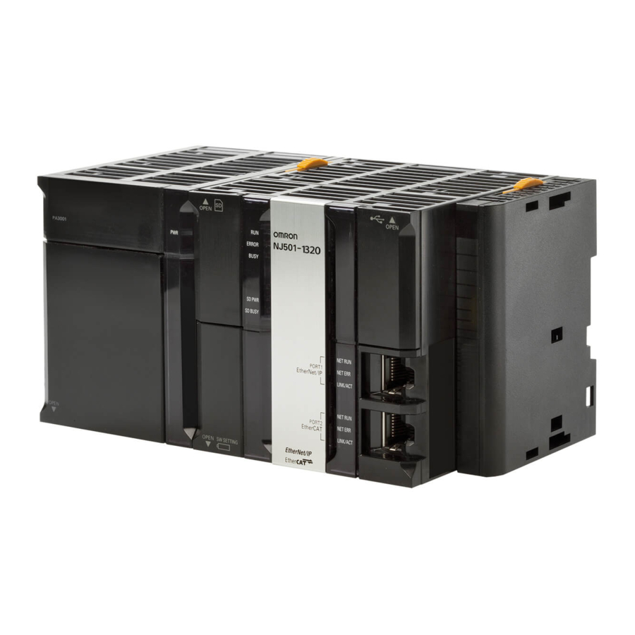
1 Overview System Configuration for Static Pick- and-place Equipment This section describes the system configuration for the static pick-and-place equipment that is ex- plained in this guide. An equipment to move a workpiece that is not moved at the specified position to the target position is called a static pick-and-place equipment in this guide. - Page 34 1 Overview Letter Name Model Version Robot Integrated CPU Unit NJ501-R300 Ver.1.41 Power Supply Unit NJ-PA3001 SCARA Robot RL4-2166000 3.0 0-0 Edit A1 eCobra 600 Pro Ethernet cable Computer (Sysmac Studio) EtherCAT Digital I/O Terminal GX-MD3218 Ethernet cable Ethernet cable T20 Pendant 10046-010 3.0.0.1...
-
Page 35: Operations Of Static Pick-And-Place Equipment
1 Overview Operations of Static Pick-and-place Equipment This section describes the operating specifications and procedures for the static pick-and-place equip- ment. 1-3-1 Operating Specifications This equipment picks up a workpiece that is not moving on the conveyor A and transfers it to the specified position on the conveyor B. -
Page 36: Operating Modes For Equipment
1 Overview Additional Information The operations for conveyor A and B are not described in this guide. Program it by the custom- er according to the operating specifications of actual equipments. 1-3-2 Operating Modes for Equipment Assume that this equipment have two operating modes, manual operation and automatic operation. Perform teaching in manual operation, and execute the actual pick-and-place operations in automatic operation. -
Page 37: Hardware
A CPU Unit that integrates the sequence control and robot control. To CPU Unit use the robot control function, you must insert the included SD Memory Card. EtherCAT-com- RL£-££££££ The OMRON robot that supports EtherCAT. patible OMRON £ robot Computer A computer that the Sysmac Studio Automation Software to make the settings for the robot integrated system and perform debugging is in- stalled. -
Page 38: Software
1 Overview Software This section describes an overview of each software in the system configuration. Use the Sysmac Studio as a development environment for the robot integrated system. 1-5-1 Sysmac Studio The Sysmac Studio provides development environment for a robot integrated system on a computer. Precautions for Correct Use For a robot integrated system, use the 64-bit edition DVD (SYSMAC-SE200D-64) with the Sys- mac Studio version 1.££. -
Page 39: User Program
V+ program The user program that is operated in the Robot Integrated CPU Unit can be programmed with V+ language. The language is a programming language for robot control for the OMRON robots. The robots can be controlled using V+ keywords. -
Page 40: Command And Data Flow
V+ pro- gram. Robot Integrated CPU Unit Robot control instructions Robot variables, Sequence control program robot I/O variables Shared variables Start, stop, or OMRON robot (Teaching monitor position variable, V+tasks etc.) V+ program 1-10 NJ-series Robot Integrated System Startup Guide (O049) - Page 41 The V+ program can control robots with V+ keywords, signal numbers, and V+ variables. The V+ program starts or stops with RC_ExecVpPrgTask from the sequence control program. Robot Integrated CPU Unit Sequence control program Shared variables OMRON robot (Execution status for the sequence control program, etc.) V+ keywords V+ program Signal numbers, V+ variables Refer to the NJ-series Robot Integrated CPU Unit User’s Manual (Cat.
- Page 42 1 Overview 1-12 NJ-series Robot Integrated System Startup Guide (O049)
- Page 43 Before You Begin This section describes the installation procedure of the Sysmac Studio and how to as- semble and wire the hardware. Installing the Sysmac Studio ................ 2-2 Installing and Wiring the System..............2-3 2-2-1 Wiring the Robot Integrated CPU Unit and the EtherCAT Digital I/O Terminal......................
-
Page 44: Installing The Sysmac Studio
2 Before You Begin Installing the Sysmac Studio The Sysmac Studio Ver.1.££ 64-bit edition DVD (SYSMAC-SE200D-64) is the Support Software that you use for the Robot Integrated System. On it, you can set up the configurations and parameters, you can create programs, and you can debug and simulate operation. Set the Sysmac Studio installation disk into the DVD-ROM drive. -
Page 45: Installing And Wiring The System
2 Before You Begin Installing and Wiring the System In the system configuration, you must wire the signal lines covered in the colored areas in the figure below and set the node address of the robot. • Wiring between the Robot Integrated CPU Unit (A) and the EtherCAT Digital I/O Terminal (F) •... -
Page 46: Setting The Node Address Of The Ethercat Digital I/O Terminal
2 Before You Begin 2-2-2 Setting the Node Address of the EtherCAT Digital I/O Terminal You must set the EtherCAT node address of the EtherCAT Digital I/O Terminal. Use the switches on the EtherCAT Digital I/O Terminal to set the EtherCAT node address. To set the node address to 1, set the x10 switch to 0 and the x1 switch to 1. -
Page 47: Setting The Ethercat Node Address Of The Robot
2 Before You Begin Precautions for Correct Use Refer to the NJ/NX-series CPU Unit Built-in EtherCAT Port User’s Manual (Cat. No. W505) for details on the Ethernet cable to be used. 2-2-4 Setting the EtherCAT Node Address of the Robot You must set the EtherCAT node address of the robot. - Page 48 2 Before You Begin Connect the XMCP connector (Red) of the XSYSTEM cable assembly and the T20 adapter ca- ble. Connect the T20 adapter cable to the T20 pendant. Connect the XFP connector (Green) of the XSYSTEM cable assembly and the front panel ca- ble.
-
Page 49: Wiring The Ethercat Digital I/O Terminal And The Solenoid Valve
2 Before You Begin 2-2-7 Wiring the EtherCAT Digital I/O Terminal and the Solenoid Valve You must wire the EtherCAT Digital I/O Terminal and the solenoid valve. Refer to the manuals for the EtherCAT Digital I/O Terminal and the solenoid valve for details on the cable wiring, and make the cable appropriately in accordance with the wiring diagrams and specifica- tions. - Page 50 2 Before You Begin NJ-series Robot Integrated System Startup Guide (O049)
-
Page 51: Implementation Example Of Static Pick-And-Place Equipment
Implementation Example of Static Pick-and-place Equipment This section describes the implementation example of the static pick-and-place equip- ment. An equipment to move a workpiece that is not moved at the specified position to the target position is called a static pick-and-place equipment in this guide. This example can realize with the sequence control program and V+ program. -
Page 52: Program Specifications For Static Pick-And-Place Equipment
3 Implementation Example of Static Pick-and-place Equipment Program Specifications for Static Pick-and-place Equipment The program specifications are described if operations of static pick-and-place equipment are control- led with the sequence control program and if the operations are controlled with the V+ program. A flow chart of a program is given below. -
Page 53: When Operations Are Controlled With Sequence Control Program
3 Implementation Example of Static Pick-and-place Equipment 3-1-1 When Operations are Controlled with Sequence Control Pro- gram The program specifications when operations of static pick-and-place equipment are controlled with the sequence control program are described below. The program consists of the following programs. Program name Language Description... - Page 54 3 Implementation Example of Static Pick-and-place Equipment Main Program "Main" (main program) is used to monitor the status of the following robots and EtherCAT Digital I/O Terminals and determine whether the automatic operation can start. Refer to the manual for each device for details on variables. Variable name Description _EC_PDSlavTbl[1]...
- Page 55 3 Implementation Example of Static Pick-and-place Equipment Variable name Description GetRCError Check whether an error caused by the Robot Control Function Module exists. _RC_RBT[0].DrvStatus.ESTOP Check whether the robot is in ESTOP state. _RC_RBT[0].DrvStatus.Manual Check that the operating mode of the robot is Manual mode. _RC_RBT[0].DrvStatus.Power- Check that the robot high power is enabled.
- Page 56 3 Implementation Example of Static Pick-and-place Equipment NJ-series Robot Integrated System Startup Guide (O049)
- Page 57 3 Implementation Example of Static Pick-and-place Equipment NJ-series Robot Integrated System Startup Guide (O049)
- Page 58 3 Implementation Example of Static Pick-and-place Equipment NJ-series Robot Integrated System Startup Guide (O049)
- Page 59 3 Implementation Example of Static Pick-and-place Equipment NJ-series Robot Integrated System Startup Guide (O049)
- Page 60 3 Implementation Example of Static Pick-and-place Equipment V+ Program The V+ program that is required for controlling operations of the static pick-and-place equipment in the sequence control program is described below. The V+ program is used to register global variables and create two programs, "loccopy" (variable copy program) and "auto"...
-
Page 61: When Operations Are Controlled With V+ Program
.PROGRAM loccopy() ; ABSTRACT: Copy location data to IEC 61131-3 global variables. ; MISC: Program created in ACE version 1.0.1.0 ;* Copyright (c) 2020 by {OMRON} GLOBAL gl.pick, gl.place, gl.wait EXTERNAL eloc_pick[], eloc_place[], eloc_wait[] EXTERNAL ebool_exe ebool_exe = TRUE ; Copy location data to external variables DECOMPOSE eloc_pick[] = gl.pick... - Page 62 3 Implementation Example of Static Pick-and-place Equipment Shared Variables The following table shows a list of shared variables that are used in the sequence control program. No. Variable name Data type Description eBool_ExeT1 BOOL Use the variable to check that the execution of V+ task 1 is started in the sequence control program.
- Page 63 3 Implementation Example of Static Pick-and-place Equipment Variable name Description _RC_RBT[0].DrvStatus.Manual Check that the operating mode of the robot is Manual mode. _RC_RBT[0].DrvStatus.Power- Check that the robot high power is enabled. Enabled A program is described below. 3-13 NJ-series Robot Integrated System Startup Guide (O049)
- Page 64 3 Implementation Example of Static Pick-and-place Equipment V+ Program This section describes the V+ program to control the static pick-and-place equipment. The V+ program is used to register global variables and create three programs, "run" (robot com- mands send program), "run.checkmode" (V+ program stop program), and "auto" (read program). ...
- Page 65 A program is described below. .PROGRAM run() ; ABSTRACT: Pick and place program ; MISC: Program created in ACE version 4.1.0.22 ;* Copyright (c) 2019 by {OMRON} AUTO ar.speed, ar.accel, ar.wait_on, ar.wait_off, ar.dist, ar.loc[5], al. safe EXTERNAL ebool_exet2 ebool_exet2 = TRUE ;...
- Page 66 A program is described below. .PROGRAM run.checkmode() ; ABSTRACT: Stop pick and place program ; MISC: Program created in ACE version 4.1.0.22 ;* Copyright (c) 2019 by {OMRON} EXTERNAL ebool_mode EXTERNAL ebool_exet1, ebool_reset ebool_exet1 = TRUE WHILE TRUE DO ; Check NJ mode and reset-button IF (ebool_mode == FALSE) OR (ebool_reset == TRUE) THEN ;...
-
Page 67: Basic Startup Procedures
3 Implementation Example of Static Pick-and-place Equipment Basic Startup Procedures This section gives an overview of the basic startup procedures to build a static pick-and-place system. First, program a machine operation, configure and check the settings using the simulator, and then run the system for fine-tuning the operation. -
Page 68: Programming And Simulation Procedures
3 Implementation Example of Static Pick-and-place Equipment Programming and Simulation Proce- dures This section describes the procedure for creating project files, programing, and setting and checking operation in simulation. The simulation function allows you to check the equipment operation in advance without purchasing actual equipment. -
Page 69: Creating The Ethercat Network Configuration
3 Implementation Example of Static Pick-and-place Equipment A project file is created and the following window is displayed. 3-3-2 Creating the EtherCAT Network Configuration Create the EtherCAT network configuration and add a robot on the network. Click Configurations and Setup in the Multiview Explorer. Setting items are displayed under Configurations and Setup in the tree. - Page 70 3 Implementation Example of Static Pick-and-place Equipment Double-click EtherCAT under Configurations and Setup in the Multiview Explorer. Or right- click EtherCAT under Configurations and Setup and select Edit from the menu. The EtherCAT Master is displayed in the EtherCAT tab page. From the Toolbox, select the group of Digital I/O.
- Page 71 3 Implementation Example of Static Pick-and-place Equipment A GX-MD3218 is registered under the EtherCAT Master. From the Toolbox, select the group of Robot. Select and drag the robot to use and drop it on the GX-MD3218 in the EthercAT tab page. Here, select Cobra 600 Pro.
-
Page 72: Creating A Sequence Control Program
3 Implementation Example of Static Pick-and-place Equipment 3-3-3 Creating a Sequence Control Program This section provides the procedure for creating a sequence control program. For details on the program to create, refer to 3-1 Program Specifications for Static Pick-and-place Equipment on page 3-2. Creating Device Variables Create device variables to control solenoid valves. - Page 73 3 Implementation Example of Static Pick-and-place Equipment Right-click on the GX-MD3218 and select Create Device Variable from the menu. Device variables are automatically registered for the I/O ports of the GX-MD3218. Defining Global Variables Define global variables used as the position data in the sequence control program. Double-click Global Variables under Programming - Data in the Multiview Explorer.
- Page 74 3 Implementation Example of Static Pick-and-place Equipment Press the Insert key in the global variable table, or right-click in the global variable table and select Create New from the menu. Enter or select setting for each item, and then press the Enter key. The global variable is registered.
- Page 75 3 Implementation Example of Static Pick-and-place Equipment This allows you to edit the name of the sequence control program. Enter the name of the sequence control program. The name of the sequence control program is changed. Double-click the section to edit. The variable table and Ladder Editor are displayed in the Edit Pane.
- Page 76 3 Implementation Example of Static Pick-and-place Equipment Click the icon displayed to the left of Program0 under Programming - POUs - Programs in the Multiview Explorer. Section0 is added under Program0. Returns to step 1 and repeat the above steps. Assigning Programs to Tasks In this section, assign the ladder diagram programs to tasks of the Robot Integrated CPU Unit.
- Page 77 3 Implementation Example of Static Pick-and-place Equipment Click the + button. A new row is added for the program to assign. Select a name of the program to use from the list of the Program name. The name of the selected program is displayed. 3-27 NJ-series Robot Integrated System Startup Guide (O049)
- Page 78 3 Implementation Example of Static Pick-and-place Equipment 3-3-4 Creating V+ Programs This section provides the procedure for creating the V+ programs. For details on the program to create, refer to 3-1 Program Specifications for Static Pick-and-place Equipment on page 3-2. Setting V+Digital I/O To control EtherCAT Slaves by V+ programs, you must assign V+ digital I/Os.
- Page 79 3 Implementation Example of Static Pick-and-place Equipment The Robot Common Settings tab page is displayed. Click the + button in the Robot Common Settings tab page. A row for registering a new V+ digital I/O is added. Click the drop-down list for Device in the newly added row, and then select Node:1 GX- MD3218(E001).
- Page 80 3 Implementation Example of Static Pick-and-place Equipment Enter 4001 for V+Digital I/O. Defining Global Variables Define the global variables for use in the V+ program. Here, the procedure to create a variable gl.wait is given below as an example, which is a global varia- ble used in the V+ program in 3-1-1 When Operations are Controlled with Sequence Control Program on page 3-3.
- Page 81 3 Implementation Example of Static Pick-and-place Equipment The Add New Variable table is displayed. Input a variable name. Select Locations from the list of variable types. For Robot, select Cobra 6000 from the list. 3-31 NJ-series Robot Integrated System Startup Guide (O049)
-
Page 82: Creating V+ Programs
3 Implementation Example of Static Pick-and-place Equipment Click the Accept button. The variable gl.wait is added to the table. Creating V+ Programs This section describes the procedure to create V+ programs. In the Multiview Explorer, select RobotControlSettings from the device list. Right-click V+ Modules under Programming in the Multiview Explorer, and select Add New Module from the menu. - Page 83 3 Implementation Example of Static Pick-and-place Equipment In the tree of the Multiview Explorer, program0 - program0 are added under V+ Modules, which allows you to edit the name of the V+ program. Enter the name of the V+ program. The name of the V+ program is changed.
-
Page 84: Placing 3D Shape Data
3 Implementation Example of Static Pick-and-place Equipment Create the program in the Edit Pane. 3-3-5 Placing 3D Shape Data Making the Robot Motion Range Visible You can make the operating range of the robot visible on the 3D Visualizer. Making the operating range visible makes it easier to set the position of the robot. - Page 85 3 Implementation Example of Static Pick-and-place Equipment In the Visibility tab page, select the Work Volume check box located under RobotControlSettings - Cobra 6000. The 3D Visualizer illustrates the robot’s operating range in gray. Click the Close button on the Scene Graph dialog box. 3-35 NJ-series Robot Integrated System Startup Guide (O049)
- Page 86 3 Implementation Example of Static Pick-and-place Equipment Importing 3D CAD Data Import the 3D CAD data of the conveyors as 3D shape data to the Sysmac Studio. This section describes the procedure to import the 3D CAD Data of Conveyor A and Conveyor B used in the equipment model in 1-3 Operations of Static Pick-and-place Equipment on page 1-5.
- Page 87 3 Implementation Example of Static Pick-and-place Equipment Additional Information Application Manager added by this operation can only be used for simulation. Do not use it for actual device Click Configurations and Setup in the Multiview Explorer. Setting items are displayed under Configurations and Setup in the tree. Right-click 3D Visualization.
- Page 88 3 Implementation Example of Static Pick-and-place Equipment Select Open my own CAD file. Click the Next button. Click the Open File button. The Open dialog box is displayed. 3-38 NJ-series Robot Integrated System Startup Guide (O049)
- Page 89 3 Implementation Example of Static Pick-and-place Equipment Select 3D CAD data to import, and then click the Open button. In this example, you select the conveyor of MISUMI Corporation whose model number is SVKN-100-1000-25-T100-IM-9-H-A for the Conveyor A. You can import the 3D CAD data with the file name extension “stp”.
- Page 90 3 Implementation Example of Static Pick-and-place Equipment Additional Information Align the conveyor top to the U face. Click the +90 Yaw button or +90 Pitch button to change the orientation of the conveyor. Click the buttons in the following order; +90 Yaw, +90 Pitch, +90 Yaw, +90 Pitch and +90 Pitch The conveyor top comes to the U face.
- Page 91 3 Implementation Example of Static Pick-and-place Equipment The Import CAD File wizard is closed and the main window is displayed again. Check that CAD Data0 is added under Configurations and Setup - 3D Visualization in the Multiview Explorer. Perform step 4 and later to import the 3D CAD data of the Conveyor B. In the Multiview Explorer, CAD Data1 is added under Configurations and Setup - 3D Visualization.
- Page 92 3 Implementation Example of Static Pick-and-place Equipment This section describes the procedure to place Conveyor A used in the equipment model in 1-3 Opera- tions of Static Pick-and-place Equipment on page 1-5 as an example. Additional Information For information on setting up in the 3D Visualizer and translating the point of view, refer to the Sysmac Studio 3D Simulation Function Operation Manual (Cat.
- Page 93 3 Implementation Example of Static Pick-and-place Equipment Select Edit Workspace Position from the menu. The Move icon consisting of colored arrows, a purple circle, and faces is displayed on the ori- gin of the 3D shape data. Drag one of the arrows, faces, or the purple circle and drop it on the place to move the 3D shape data.
- Page 94 3 Implementation Example of Static Pick-and-place Equipment Additional Information When the Move icon is hidden, click the 3D shape data to display it. Right-click the 3D shape data you are moving in the 3D Visualizer. The menu commands are displayed. Select Edit Workspace Position from the menu to clear the selection.
- Page 95 3 Implementation Example of Static Pick-and-place Equipment The Rotate icon is displayed on the 3D shape data. Drag and drop the handle of the Rotate icon to rotate the 3D shape data around the axis to an appropriate orientation. The icon has red, green, and blue handles, which represent rotation around the X-axis, Y-axis, and Z-axis, respectively.
- Page 96 3 Implementation Example of Static Pick-and-place Equipment Right-click the 3D shape data that you were adjusting the orientation in the 3D Visualizer. The menu commands are displayed. Select Direct Position Edit from the menu. The input fields for editing the position of the 3D shape data is displayed. Enter values in mm in the X, Y, and Z fields to move the 3D shape data to an appropriate posi- tion.
- Page 97 3 Implementation Example of Static Pick-and-place Equipment Click the Edit Workspace Orientation icon. The input fields for editing the orientation of the 3D shape data is displayed. Enter values in degree in the input fields for Yaw, Pitch, and Roll to adjust the orientation of the 3D shape data.
- Page 98 3 Implementation Example of Static Pick-and-place Equipment Precautions for Correct Use Refer to the Sysmac Studio 3D Simulation Function Operation Manual (Cat. No. W618) for de- tails on coordinate system in the 3D Visualizer. Perform step 2 and later to adjust the position and orientation of the CAD Data1 of Conveyor B. The 3D shape data of Conveyor A and Conveyor B are now placed in the appropriate positions in the 3D Visualizer.
- Page 99 3 Implementation Example of Static Pick-and-place Equipment Select 3D Visualizer from the View menu on the main window of the Sysmac Studio. The 3D Visualizer is displayed on the right side of the main window. In the 3D Visualizer, click the Scene Graph icon. The Scene Graph dialog box is displayed.
- Page 100 3 Implementation Example of Static Pick-and-place Equipment Click the Collision Filter tab. Click the + button in the Collision Filter Group Items column for the Collision Filter Group. A new row with the Collision Filter Group Name set as Group0 is added on the Scene Graph dialog box.
- Page 101 3 Implementation Example of Static Pick-and-place Equipment Repeat step 4 above. A new row with the Collision Filter Group Name set as Group1 is added on the Scene Graph dialog box. Click the ... button in the Collision Filter Group Items column for Group0 - [0]. The Select a collision filter group item dialog box is displayed.
- Page 102 3 Implementation Example of Static Pick-and-place Equipment Select new_Controller_0 - RobotControlSettings - Robots - Cobra 6000 - Entire Robot in the tree, and then click the Select button. The Select a collision filter group item dialog box closes and the Scene Graph dialog box is displayed again.
- Page 103 3 Implementation Example of Static Pick-and-place Equipment Click the ... button in the Collision Filter Group Items column whose Collision Filter Group Name is Group1 - [0]. The Select a collision filter group item dialog box is displayed. Select ApplicationManager0 - 3D Visualization - CAD Data0 from the tree, and then click the Select button.
- Page 104 3 Implementation Example of Static Pick-and-place Equipment The Select a collision filter group item dialog box closes and the Scene Graph dialog box is displayed again. CAD Data0 is registered to the Collision Filter Group Items column for Group1 - [0]. Check that the Valid check boxes are all selected.
- Page 105 3 Implementation Example of Static Pick-and-place Equipment Follow the step 8 to 10 to register CAD Data1 for Group1 - [1]. CAD Data1 is registered to the Collision Filter Group Items column for Group1 - [1]. Click the Close button in the Scene Graph dialog box. Now, the settings for checking the conflict between the robot, Conveyor A, and Conveyor B have been completed.
-
Page 106: Starting Simulation
3 Implementation Example of Static Pick-and-place Equipment 3-3-6 Starting Simulation Enabling Robot Simulation Function Enable the simulation function of the Sysmac Studio. To simulate the operation of the robot, open the project file in EMULATION mode. If you want to know whether the project file opened on the Sysmac Studio is in EMULATION mode or not, check the status bar on the main window. -
Page 107: Teaching Positions
3 Implementation Example of Static Pick-and-place Equipment 3-3-7 Teaching Positions This section describes the procedure to use the simulation function of the Sysmac Studio for teaching the positions. The target of teaching in this equipment model is the wait position of the robot and the pick-up and place positions of the workpiece. - Page 108 3 Implementation Example of Static Pick-and-place Equipment When teaching positions to the robot, you must store the position data of the robot in the V+ position variables. Here, create the following position variables. Corresponding IEC Variable name Data type Application variable gl.pick Location...
- Page 109 3 Implementation Example of Static Pick-and-place Equipment Move the mouse cursor to the tool center point of the robot and click on it. When you click the Move icon, the outline of the robot is highlighted with black lines. Drag the mouse cursor. The tool center point moves to follow the mouse cursor.
- Page 110 3 Implementation Example of Static Pick-and-place Equipment Move the tool center point to the position where it overlaps the conveyor, which is the position you specify. The collision detection function set in Activating Collision Detection Function on page 3-48 de- tects a conflict between the robot and the conveyor and the color of them changes to gray.
- Page 111 3 Implementation Example of Static Pick-and-place Equipment The 3D Visualizer is displayed on the right side of the main window. Select RobotControlSettings from the device list in the Multiview Explorer. Select V+ Jog Control from the View menu on the main window. The V+ Jog Control pane appears on the right side of the main window.
- Page 112 3 Implementation Example of Static Pick-and-place Equipment From the drop-down list of Jog Control on V+ Jog Control pane, select the coordinate system of World, Joint, or Tool. When World is selected, positions of the robot can be specified in the robot coordinate system, and when Joint is selected, the position can be set in the coordinate system of the joint.
- Page 113 3 Implementation Example of Static Pick-and-place Equipment Press and hold the arrow button labeled + or - of Jog Control in the V+ Jog Control pane. The labels + and - on the arrow buttons represent positive or negative directions on the speci- fied coordinate system.
- Page 114 3 Implementation Example of Static Pick-and-place Equipment Take step 4 to 6 again to move the robot to the position and posture you want to specify. Now the robot position has been configured. Saving Current Positions to Variables The current positions of the robot set by teaching must be saved in the V+ variables. The procedure to save the current position of the robot to the already created V+ variable is described below.
- Page 115 3 Implementation Example of Static Pick-and-place Equipment Click Location in the V+ Jog Control pane. The field to set the position variable is displayed. Selects a variable that you want to set the current position or an element of the array variable from the drop-down list.
- Page 116 3 Implementation Example of Static Pick-and-place Equipment The variable name and values set in the selected variable are displayed. Select the variable gl.wait. Click the Here button of Location in the V+ Jog Control pane. 3-66 NJ-series Robot Integrated System Startup Guide (O049)
-
Page 117: Setting Up Automatic Loading Of V+ Programs And Variables At Power On
3 Implementation Example of Static Pick-and-place Equipment The current position is registered to the value of the selected variable. Now you have registered the current position of the robot to the V+ variable. Additional Information When the sequence control program controls the robot operation, the variable copy program "loccopy"... - Page 118 3 Implementation Example of Static Pick-and-place Equipment This section describes the setting procedure for automatically loading the V+ programs and V+ global variables to the Robot Integrated CPU Unit when its power is turned ON. Select RobotControlSettings from the device list in the Multiview Explorer. Click Configurations and Setup in the Multiview Explorer.
- Page 119 3 Implementation Example of Static Pick-and-place Equipment Click the Generate Auto Module button in the Save Configuration tab page. The module name auto is added to the module list in the Save Configuration tab page. In the tree of the Multiview Explorer, V+ Modules - auto are added under Programming. Select Save from the File menu.
-
Page 120: Running The Program And Checking Operation
3 Implementation Example of Static Pick-and-place Equipment The Robot Integrated CPU Unit is now configured to automatically load the V+ programs and V+ glob- al variables when it is powered ON. The program auto starts automatically when the Robot Integrated CPU Unit is powered ON and reads the saved V+ programs and V+ global variables. - Page 121 3 Implementation Example of Static Pick-and-place Equipment The Task Status Control pane appears on the right side of the main window. Click the power button in the Task Status Control pane. The color of the power button changes from green to red. Click the power button again in the Task Status Control pane.
- Page 122 3 Implementation Example of Static Pick-and-place Equipment The power button turns from red to green. In the Multiview Explorer, select new_Controller_0 from the device list. Select 3D Visualizer from the View menu on the main window of the Sysmac Studio. The 3D Visualizer is displayed on the right side of the main window.
- Page 123 3 Implementation Example of Static Pick-and-place Equipment Type gStart in the Name column on the Watch (Project)1 tab page. The Online value column displays the current value of False for the internal variable gStart in Program0. Click the TRUE button in the Modify column for the variable gStart in the Watch (Project)1 tab page.
- Page 124 3 Implementation Example of Static Pick-and-place Equipment The robot moves to the workpiece pick-up position and pauses. After that, it moves to the robot wait position and stops. During operation, check that the robot does not turn gray in locations other than the workpiece pick-up position and workpiece place position.
-
Page 125: Setup Procedure For Actual System
3 Implementation Example of Static Pick-and-place Equipment Setup Procedure for Actual System This section describes the procedures for wiring devices, checking operation on the actual system, and adjusting the system. Check operation with the simulation function before you check operation on the actual system. Precautions for Correct Use When you operate the robot in MANUAL mode with the T20 pendant, you must plug the iCS Commissioning Jumper into the XBELTIO connector and change the setting for the Teach Re-... - Page 126 3 Implementation Example of Static Pick-and-place Equipment Click the Direct connection via Ethernet from the Communication type, and then click the OK button. The Communications Setup dialog box is closed. Click the Disable emulation mode icon in the toolbar. The confirmation dialog box for Disable emulation mode is displayed. Click the OK button.
-
Page 127: Transferring Settings And Programs
3 Implementation Example of Static Pick-and-place Equipment 3-4-2 Transferring Settings and Programs The settings and programs in the project file are transferred from the Sysmac Studio to the Robot Inte- grated CPU Unit. Select Controler - Synchoronizatioin from the menu bar on the Sysmac Studio. The comparison of the user program and parameter settings between the Sysmac Studio and the Controller is started. - Page 128 3 Implementation Example of Static Pick-and-place Equipment Click the Transfer to Controller button. Confirm that "The Synchronization process successfully finished." is diaplayed, and then click the Close button. Select RobotControlSettings from the device list in the Multiview Explorer. 3-78 NJ-series Robot Integrated System Startup Guide (O049)
- Page 129 3 Implementation Example of Static Pick-and-place Equipment Click the Push to V+ Memory icon in the toolbar. Push to V+ Memory is displayed during the processing. Confirm that the Robot Integrated CPU Unit is turned ON normally. The status of indicators for normal operation is given below. Indicators Status RUN indicator...
-
Page 130: Teaching
3 Implementation Example of Static Pick-and-place Equipment 3-4-3 Teaching A robot is operated actually to check and correct teaching data. Move the robot to the teaching position set in the simulation operation actually, and adjust the position if necessary. The teaching position data is saved in the SD Memory Card so that the data is retained after the power supply to the Robot Integrated CPU Unit is turned OFF. - Page 131 3 Implementation Example of Static Pick-and-place Equipment Press and release the ROBOT POWER button while the enable switch keeps to Position 2 (half-way). After a few seconds, the robot high power is turned ON and the ROBOT POWER button lights. If you release the enable switch (Position 1) or press the enable switch again from Position 2 (half- way) (Position 3), the robot high power is turned OFF.
- Page 132 3 Implementation Example of Static Pick-and-place Equipment Precautions for Correct Use Perform the adjustment in the above order in the table. If the adjustment is performed in differ- ent order, the robot may move to the unintended travel route and contact to the equipments such as a conveyor, and then the devices may be damaged.
- Page 133 3 Implementation Example of Static Pick-and-place Equipment The SYSTEM MAINTENANCE screen is displayed. Press the up or down arrow button to select Approach Dist field. 3-83 NJ-series Robot Integrated System Startup Guide (O049)
- Page 134 3 Implementation Example of Static Pick-and-place Equipment Press the OK button. Press the up or down arrow button to change the value of Approach Dist field. You can select the height to rise and fall in the range of 1 to 200 mm. Assume that the value of height to rise and fall is 40 in this step.
- Page 135 3 Implementation Example of Static Pick-and-place Equipment Press the MENU button to back to HOME1 screen. Press the F2 button (Loc). The AVAILABLE LOCATIONS screen is displayed. 3-85 NJ-series Robot Integrated System Startup Guide (O049)
- Page 136 3 Implementation Example of Static Pick-and-place Equipment On the AVAILABLE LOCATIONS screen, use the arrow buttons to select the teaching position from the list of locations. Press the F4 button (Next>). The display for the soft keys changes on the bottom of the screen. If the variable selected in step 10 is gl.pick or gl.place, press and hold the F2 button (Appro).
- Page 137 3 Implementation Example of Static Pick-and-place Equipment The robot moves linearly to the top of the selected position. Press and hold the F1 button (JogTo). The robot moves linearly to the selected position. When the robot moves to the selected position, release the F1 button (JogTo). If there is no problem with the position and posture after the move, proceed to step 20.
- Page 138 3 Implementation Example of Static Pick-and-place Equipment The TEACH screen for the selected location is displayed. Press the Jog Mode button until the desired mode is displayed in the Jog Mode Indicator area. Assumes that the adjustment of the position in World Mode is performed in this step, and press the button until WORLD is displayed.
- Page 139 3 Implementation Example of Static Pick-and-place Equipment Press the OK button. The value of position is updated to the current robot position. Press the F2 (Loc) button and then F4 button (Next>). The AVAILABLE LOCATIONS screen is displayed again. 3-89 NJ-series Robot Integrated System Startup Guide (O049)
- Page 140 3 Implementation Example of Static Pick-and-place Equipment If the variable selected in step 10 is gl.pick or gl.place, press and hold the F2 button (Appro). The robot moves linearly to the top of the selected position. If there are still positions left to adjust, return to step 10. Saving Teaching Position in SD Memory Card The teaching position data is saved in the SD Memory Card so that the data is retained after the pow- er supply to the Robot Integrated CPU Unit is turned OFF.
-
Page 141: Executing Program To Check Operation
3 Implementation Example of Static Pick-and-place Equipment Click the Pull from V+ Memory icon in the toolbar of the Multiview Explorer. Select Configurations and Setup - Save Configuration in the Multiview Explorer. Click the Save To Controller button in the Save Configuration tab page. Click File - Save from the menu bar. - Page 142 3 Implementation Example of Static Pick-and-place Equipment Manual Mode Auto Mode Operating mode switch Press the Robot Power button on the front panel. ROBOT POWER button After a few seconds, the ROBOT POWER button lights. ROBOT POWER button Select View - Watch Tab Page from the menu bar in the main window of the Sysmac Studio on the computer.
- Page 143 3 Implementation Example of Static Pick-and-place Equipment Click the TRUE button in the Modify column for gStart. The robot performs pick-and-place operation according to the program. If you use this program actually, write a program so that you can operate gStart variable from the HMI. Precautions for Correct Use If the operation is controlled with the V+ program and the operating mode of the Robot Integrat- ed CPU Unit is switched from RUN mode to PROGRAM mode, and then to RUN mode again,...
- Page 144 3 Implementation Example of Static Pick-and-place Equipment 3-94 NJ-series Robot Integrated System Startup Guide (O049)
-
Page 145: Appendices
Appendices Designing Example of the Safety Functions for the Pick-and- place Equipment..................... A-2 A-1-1 Pick-and-place Equipment Configuration ............A-2 A-1-2 Hazards ......................A-4 A-1-3 Protective Measure ..................A-4 A-1-4 Safety Functions....................A-4 A-1-5 Safety System Configuration and Devices ............A-5 A-1-6 Installation and Wiring .................. -
Page 146: Designing Example Of The Safety Functions For The Pick-And-Place Equipment
Appendices A-1 Designing Example of the Safety Functions for the Pick-and-place Equipment This section describes the designing example of the safety functions for the pick-and-place equipment. Precautions for Correct Use You must implement the actual safety measures based on the Robot Safety Guide (Cat. No. I590) and risk assessment. - Page 147 Appendices Front Back NJ-series Robot Integrated System Startup Guide (O049)
-
Page 148: A-1-2 Hazards
E-STOP button on front panel A-1-4 Safety Functions You must decide the safety function of each safety device for the case it operated. The functions need to be decided for each operating mode of the OMRON robot. NJ-series Robot Integrated System Startup Guide (O049) -
Page 149: A-1-5 Safety System Configuration And Devices
Appendices Auto Mode Set the safety functions when the operating mode of the OMRON robot is in Auto mode as shown in the table below. Safety device Safety function Recovery Emergency stop pushbutton switch 1 Stop the robot when pressed... - Page 150 Safety door switches switches Safety light curtains Safety relays Front panel XMCP T20 Pendant XUSR OMRON robot Configuration Devices The safety system configuration in this guide uses the devices shown in the table below. NJ-series Robot Integrated System Startup Guide (O049)
-
Page 151: A-1-6 Installation And Wiring
Appendices Manufac- Name Model Description turer EtherNet/IP Coupler NX-EIC202 OMRON A Coupler Unit that supports EtherNet/IP. Unit This Unit can compose a Slave Terminal by connecting with an NX Unit. Safety CPU Unit NX-SL3300 OMRON A Unit that runs safety programs. - Page 152 Appendices Wiring the Power Supplies The power supply wirings and grounding for the EtherNet/IP Coupler Unit are shown in the figure be- low. Unit power supply (20 VDC) I/O power supply (5 to 24 VDC) Ground of 100 W or less •...
- Page 153 Appendices Wiring the Emergency Stop Pushbutton Switch Connect the emergency stop pushbutton switch to the Safety Input Unit (N2). NX-SIH400 (N2) Wiring the Safety Light Curtain Connect the safety light curtain to the I/O power supply and Safety Input Unit (N3). Safety light curtain Safety light curtain I/O power...
- Page 154 Appendices Non-contact door switch Non-contact door switch I/O power supply 24 VDC NX-SIH400 (N4) Non-contact door switch input Non-contact door switch output Non-contact door switch input Non-contact door switch output Wiring the Reset Switch Connect the reset switch to the Safety Input Unit (N5). NX-SIH400 (N5) Wiring the Robot...
- Page 155 Appendices NX-SOD400 Robot (N6) XUSR-3 Line emergency stop CH1 XUSR-16 XUSR-4 Line emergency stop CH2 XUSR-17 XUSR-5 Muted safety gate CH1 XUSR-18 XUSR-6 Muted safety gate CH2 XUSR-19 XUSR-1 User emergency stop CH1 XUSR-14 XUSR-2 User emergency stop CH2 XUSR-15 A-11 NJ-series Robot Integrated System Startup Guide (O049)
- Page 156 Appendices NX-SIH400 Robot (N5) XUSR-7 Emergency stop status command CH1 XUSR-20 XUSR-8 Emergency stop status command CH2 XUSR-21 XUSR-9 Manual/auto status command XUSR-22 XUSR-10 Manual/auto status command XUSR-23 Wiring the Safety Relays for Operation Check Connect the contact b of each safety relay L1 to L4 to the Safety Input Unit (N5) for checking the oper- ation of each contact a.
-
Page 157: A-1-7 Settings And Programming
Appendices NX-SOD400 NX-SIH400 (N6) (N5) A-1-7 Settings and Programming This section describes the settings and programming related to the safety functions. Refer to the NX-series Safety Control Unit Instructions Reference Manual (Cat. No. Z931) for informa- tion on the instructions for the Safety CPU Unit. Refer to the NX-series Safety Control Unit User’s Manual (Cat. - Page 158 Appendices Set the Safety Input Unit (N3) as shown below. Set the Safety Input Unit (N4) as shown below. Set the Safety Input Unit (N5) as shown below. A-14 NJ-series Robot Integrated System Startup Guide (O049)
- Page 159 Appendices Set the Safety Output Unit (N6) as shown below. Registering Device Variables Use the Sysmac Studio and set the device variables of each Safety I/O Unit. A-15 NJ-series Robot Integrated System Startup Guide (O049)
- Page 160 Appendices Safety Programs Use the Sysmac Studio to create variables and programs as shown below. Create variables as shown below. A-16 NJ-series Robot Integrated System Startup Guide (O049)
- Page 161 Appendices Create programs as shown below. A-17 NJ-series Robot Integrated System Startup Guide (O049)
- Page 162 Appendices A-18 NJ-series Robot Integrated System Startup Guide (O049)
- Page 163 Appendices A-19 NJ-series Robot Integrated System Startup Guide (O049)
- Page 164 Appendices A-20 NJ-series Robot Integrated System Startup Guide (O049)
-
Page 165: Setting Items On The Sysmac Studio And The Setting Targets
Appendices A-2 Setting Items on the Sysmac Studio and the Setting Targets The correspondances between the items in the Multiview Explorer of the Sysmac Studio and each hardware are provided below. If you select new_Controller_0 for the device in the Multiview Explorer, the settings for a sequence control program of a Robot Integrated CPU Unit, and if you select RobotControlSettings, the settings for a V+ program of a Robot Integrated CPU Unit are made. -
Page 166: Using Troubleshooting Functions
Appendices A-3 Using Troubleshooting Functions Refer to the Sysmac Studio Robot Integrated System Building Function with Robot Integrated CPU Unit Operation Manual (Cat. No. W595) for the operation procedure of the troubleshooting functions on the Sysmac Studio. A-22 NJ-series Robot Integrated System Startup Guide (O049) - Page 168 The Netherlands Hoffman Estates, IL 60169 U.S.A. Tel: (31)2356-81-300/Fax: (31)2356-81-388 Tel: (1) 847-843-7900/Fax: (1) 847-843-7787 © OMRON Corporation 2020 All Rights Reserved. OMRON (CHINA) CO., LTD. OMRON ASIA PACIFIC PTE. LTD. In the interest of product improvement, Room 2211, Bank of China Tower, No.
Need help?
Do you have a question about the NJ501-R 00 Series and is the answer not in the manual?
Questions and answers