Table of Contents
Advertisement
Quick Links
About This Manual
P/N: 4710.00447A09
Product Model: S22/S22 Exp/S22 Pro/S20 Plus/M22
Release Date: June, 2019
Copyright © 2014-2019 SonoScape Medical Corp. All rights reserved.
Statement
SonoScape Medical Corp. (hereinafter called SonoScape) owns the intellectual property rights to this manual, and also
maintains the contents of this manual as confidential information. This manual is a reference for the operation, maintenance
and cleaning of this product and does not convey any license under the patent rights of SonoScape, nor the rights of others.
This manual contains the information protected by copyrights or patents. Reproduction, amendment or translation of this
manual in any manner whatsoever without the written permission of SonoScape is strictly prohibited.
All information contained in this manual is believed to be correct. SonoScape shall not be liable for errors contained herein or
for incidental or consequential damages in connection with the furnishing, performance or use of this manual. SonoScape does
not assume any liability arising out of any infringements of patents or other rights of third parties.
This manual is based on the maximum configuration and therefore some contents may not apply to your product.
This manual is subject to change without prior notice and legal obligation.
Manufacturer's Responsibility
SonoScape is responsible for the effects on safety, reliability and performance of this product, only if all the following
requirements are met.
●
All installation operations, expansions, changes, modifications and repairs of this product are conducted by SonoScape
authorized personnel.
●
The use or application of the product or the use of parts or accessories is approved by SonoScape.
●
The electrical installation of the relevant room complies with the applicable national and local requirements.
●
The product is used in accordance with the instructions for use.
Documentation
SonoScape provides the documentation consisting of various manuals:
●
The basic user manual describes the basic functions and operating procedures of the system.
The advanced user manual provides information about the measurements and calculations available in each mode.
●
Understand the meanings of the following items clearly before reading this manual.
Item
Meaning
Indicates a potentially hazardous situation which, if not avoided, could result in death or serious injury.
!
Indicates a potentially hazardous situation which, if not avoided, may result in malfunction or damage of
the system.
Indicates a potentially biological hazardous situation which, if not avoided, may result in disease
transmission.
NOTE
Indicates precautions or recommendations that should be used in operating the system.
Advertisement
Table of Contents

Related Manuals for Sonoscape M22


Summary of Contents for Sonoscape M22
- Page 1 This manual is a reference for the operation, maintenance and cleaning of this product and does not convey any license under the patent rights of SonoScape, nor the rights of others.
- Page 2 Select a menu item or a key following the path. Contact Information Manufacturer: SonoScape Medical Corp. Address: Room 201 & 202, 12th Building, Shenzhen Software Park Phase II, 1 Keji Middle 2nd Road, Yuehai Subdistrict, Nanshan District, Shenzhen, 518057, Guangdong, China...
-
Page 3: Table Of Contents
Contents 1 S afety ..................................1 Intended Use ................................1 Safety Precautions ................................ 1 1.2.1 Electrical Safety ............................... 1 1.2.2 Mechanical Safety ............................2 1.2.3 Accessories Caring ............................3 1.2.4 Biohazard Considerations ..........................3 Acoustic Power Principle ............................. 3 1.3.1 Biological Safety .............................. 4 1.3.2 ALARA ................................ - Page 4 Contents 3.7.3 Connecting the Network Printer ........................25 3.7.4 Connecting the USB Printer ........................... 26 4 C ustomizing Your System ..........................27 General System Settings ............................27 4.1.1 General Settings ............................. 27 4.1.2 Display Settings ............................. 29 4.1.3 Storage Settings .............................. 30 4.1.4 Defined-Key Settings .............................
- Page 5 Contents Selecting a Probe and an Exam Type ......................... 63 6.1.1 Customizing A Preset ............................. 63 6.1.2 To arrange the presets display ........................64 Acquiring B-Mode Images............................65 6.2.1 Entering B Mode ............................65 6.2.2 Optimizing B-Mode Images ........................... 65 Acquiring Color Flow Images............................
- Page 6 Contents 9.2.4 Setting Render Mode ........................... 100 9.2.5 Cropping Reviews ............................101 9.2.6 Moving/Rotating/Magnifying Images ......................102 9.2.7 Optimizing 3D Image ........................... 103 9.2.8 Observing Reference Image by the Plane ....................103 9.2.9 Observing Reviews by the Slice ........................104 9.2.10 Setting the Scan Mode ..........................
- Page 7 Contents 12.5 Importing Data to the System ..........................121 13 W orking with DICOM ........................... 123 13.1 Verifying Connectivity ............................. 123 13.2 DICOM Storage ............................... 123 13.2.1 Storing the Current Image ..........................123 13.2.2 Storing Patient Data ............................. 123 13.3 DICOM Print................................124 13.3.1 Print the Current Image ..........................
- Page 8 Contents Recommended Separation Distances between Portable and Mobile RF Communications Equipment and the Equipment ................................... 150 Appendix C In Situ, Derated, and Water Value Intensities ................151 Appendix D Recommended Coupling Gel, Cleaner and Disinfectant ............152 Coupling Gel ................................152 Cleaner ..................................153 Disinfectant ................................153 Appendix E Acoustic Output Data ........................154...
-
Page 9: Afety
1 S afety This chapter describes the important information for operating this ultrasound system. To ensure the safety of both operator and patient, please read the relevant details in this chapter carefully before using this system. You should be thoroughly familiar with the precautions provided in this manual. Otherwise, the manufacturer is not responsible for the effects on safety, reliability and performance of the system. -
Page 10: Mechanical Safety
1 Safety ● Within the environment that is 1.8 meters (6 feet) around a patient, connect peripherals to the auxiliary power outlet which is capable of isolation protection; or, power the peripherals by the auxiliary output cable or the isolation transformer complied with EN/IEC 60601-1, or the power input of the same safety level. ●... -
Page 11: Accessories Caring
1 Safety ● Disconnect the foot switch and the power cable before moving the system. ● Do not knock or shake the system. ● Ensure that the casters are intact and can rotate well before moving the system. ● Always use the handle to move the system. ●... -
Page 12: Biological Safety
1 Safety ● You should be familiar with the performances and operations of the system, observe the ultrasound output parameters on the screen at all times. 1.3.1 Biological Safety Diagnostic ultrasound is recognized as being safe, but the possibility of biological effects exists when using it in high exposure levels and long exposure times. -
Page 13: Transducer Surface Temperature Limits
1 Safety − Cranial Bone Thermal Index (TIC) is used when bone is near the skin surface as in transcranial examination, it provides an estimate of potential temperature rise in the bone or adjacent soft tissue. ■ MI/TI Display TI and MI values are displayed in real time on the screen. The operator should observe these index values during examinations and ensure that exposure time and output values are maintained at the minimum amounts needed for effective diagnosis. - Page 14 1 Safety Symbol Meaning Type BF applied part Main switch OFF Main switch ON On/Standby switch Foot switch connector Protective earth (ground) Equipotentiality Alternating current Degree of IP protection Non-ionizing electromagnetic radiation Manufacturer Date of manufacture Follow instructions for use Network port USB port Fragile...
- Page 15 1 Safety Symbol Meaning Maximum stacking limit of packages Maximum of two layers allowed for the monitor Keep this way upward Serial number Rechargeable (for battery only) This symbol indicates that waste electrical and electronic equipment must not be disposed of as unsorted municipal waste and must be collected separately. Please contact an authorized representative of the manufacturer for information concerning the decommissioning of your equipment.
- Page 16 T h i s p a g e i s i n t e n t i o n a l l y l e f t b l a n k .
-
Page 17: Ystem Overview
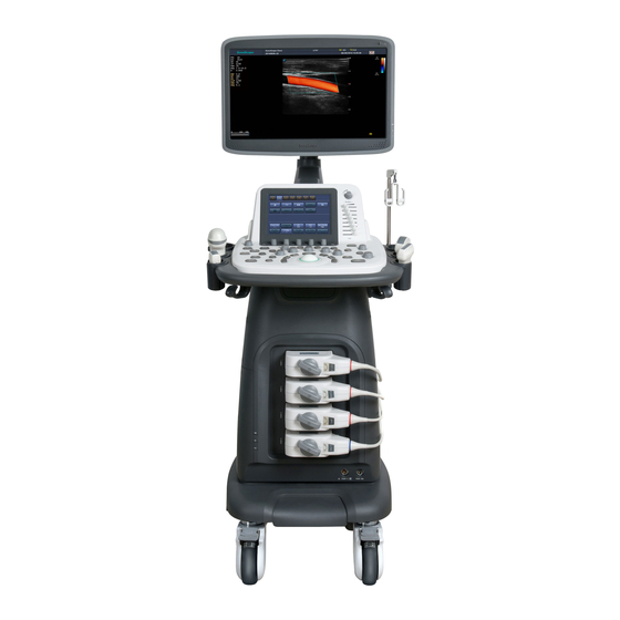
2 S ystem Overview This ultrasound system adopts advanced ultrasonic Doppler technologies. To ensure the performance and availability of this ultrasound system, you should be thoroughly familiar with the operations of system components, the control panel, the key panel and the basic screen. System Configuration The standard system configuration mainly consists of the following items: ●... -
Page 18: Peripheral Device Panel
2 System Overview LCD Monitor 13 Pencil Probe Port Touch Screen 14 Probe Holder Coupling Gel Holder 15 Engineering USB Port Control Panel 16 Cable Hanger Front Panel 17 Speaker Transducer Cable Hanger 18 Fan Probe Port 19 Cable Hanger Power Indicator 20 Dust Filter Charging/Discharging Indicator... -
Page 19: Control Panel
2 System Overview Name Description ECG Port (optional) Used for connecting the ECG cable. Video Output Used for connecting a video device to acquire compound signals, such as video printer. 2.2.3 Control Panel <28> <29> <1> <30> <7> <8> <6> <9> <2>... - Page 20 2 System Overview Name Description <6> Scale Knob Rotate it to adjust the image when activating the zoom feature. <7> Zoom Press it to activate the zoom feature. <8> 3D/4D Press it to enter or exit the 3D/4D mode. <9> Dual Press it to enter the dual split display.
- Page 21 2 System Overview Name Description Press to activate the basic measurement and calculation features. <26> Caliper ● Press it to perform the distance measurement in the 2D (B/CFM/PDI/TDI)/ M/3D/4D mode. ● Or, press it to activate the velocity measurement in the PW/CW mode. <27>...
-
Page 22: Basic Screen
2 System Overview 2.2.4 Basic Screen MI 0.2 TIS 0.7 12/03/2016 14:30:30 Sonoscape Operator 20121212234565 Patient cm/s PAT: 37℃ TIP:28℃ Figure 2-4 Basic Screen Logo 13 Depth Scale and Focal Position Institution Name 14 Clipboard Patient ID 15 Network Connection Status... - Page 23 2 System Overview To avoid damaging the touch screen, ● Do not expose it in direct sunlight. ● Tap it gently with fingers. ● Do not operate it with a sharp or hard object. ● Do not locate it in environmental temperature of sudden changes. ●...
- Page 24 2 System Overview Cancel C-Vascular Thyroid Breast P-Vascular U-Nerve L-Nerve Figure 2-6 Application Mode Screen ■ Imaging Mode Menu The imaging mode menu (as shown below) is used to select the imaging mode, optimize the image or adjust parameters. Select an exam type from the application mode screen to enter the following screen. Imaging Mode buttons Pannoramic...
- Page 25 2 System Overview CARD Breast Clear Delete Exit Figure 2-8 Body Mark Menu ■ Measurement Menu The measurement menu is used to select the measurement item to be performed. Caliper Calc Press the key on the control panel to enter the basic measurement menu. Or, press the key on the control panel to the application-specific measurement menu.
- Page 26 2 System Overview Edit Enable ! & Back Space Enter Caps Lock Shift Ctrl Space : — “ ‘ ; 、 < > Figure 2-10 Key Panel of Touch Screen Basic User Manual...
-
Page 27: Reparing The System
3 P reparing the System System preparation is necessary performed before using the system. The preparation includes but is not limited to moving, positioning or adjusting the system, connecting the probe and the peripheral devices.. System Assembly Only service personnel authorized by the manufacturer can assemble the system. Ensure the system is firmly assembled before it is powered on. -
Page 28: System Moving/Positioning
3 Preparing the System System Moving/Positioning Leave at least 20cm at the back and both sides of the system for ventilation. Otherwise, the temperature rise could cause failures. Unlock Lock Brake Perform the following steps to position the system. 1. Unlock the four foot brakes. 2. -
Page 29: Using The Battery
3 Preparing the System 3.3.2 Using the Battery ● Do not disassemble or alter the battery. Otherwise, there is a danger of explosion. ● Replace the battery with the same or the equivalent type. ● Do not short-circuit the battery by directly connecting the system with metal objects. ●... -
Page 30: Powering On/Off The System
3 Preparing the System Status Indicator Mains Supply Battery Supply Green Mains Supply Indicator Green, full capacity Battery Discharging Indicator Yellow, low capacity Blinking yellow, extremely low capacity, the system automatically shuts down and the buzzer beeps. Powering On/Off the System ● Do not power off the system during a system upgrade or a data transmission. ●... -
Page 31: Adjusting The Display Monitor
3 Preparing the System 10cm 30° 30° ● To adjust the monitor vertically, move the upper arm towards to or backwards from the lower arm. ● To adjust the monitor horizontally, swivel the upper arm left or right. 3.5.2 Adjusting the Display Monitor ■ ... -
Page 32: Connecting The Probe
3 Preparing the System ■ To adjust the brightness and contrast Adjusting the LCD monitor’s brightness and contrast is one of the most important factors for obtaining the optimum image. The proper setup displays a complete gray scale. The lowest level of black should just disappear into the background and the highest white should be bright, but not saturated. -
Page 33: Connecting The Video Printer
3 Preparing the System Connect the foot switch to the foot switch port of the system as the figure shows below. Ultrasound system Foot SW Used for printing Used for image freezing 3.7.2 Connecting the Video Printer VIDEO OUT VIDEO INPUT PRINT REMOTE Ultrasound system Video printer Connect the video printer to the system by BNC cable and Remote Control cable provided by the manufacturer. -
Page 34: Connecting The Usb Printer
3 Preparing the System TCP IP Config, 4. Press to select and then press to confirm. Manual 5. Press to select , and then press to confirm. 192.168.254.103 6. An IP address is displayed, change it to by pressing , and then press 7. -
Page 35: Ustomizing Your System
4 C ustomizing Your System The System Setting menu allows you to specify general system settings, printing, measurement and calculation settings. You can also define the annotation library and shortcut keys. All your customized settings can remain even after rebooting the system. After starting up the system, the LCD monitor displays the system desktop and the touch screen displays the application mode Setup System Setting... - Page 36 4 Customizing Your System Item Description Hospital Name Enter the institution’s name. Freeze Response Select the feature to be enabled after you select the Freeze key. Trackball Adjust the sensitivity for the trackball movement. A greater value brings about a higher Sensitivity sensitivity.
-
Page 37: Display Settings
4 Customizing Your System 4.1.2 Display Settings System Setting General Storage KeyConfig General Display Peripheral Color of ROI Cyan Comment Display Format V1/2 Bodymark Measure Screen Saver Touch Screen Screen Saver Delay(min) 30 Report Annot Font Size Medium DICOM Load Default User Security About Save&Exit... -
Page 38: Storage Settings
4 Customizing Your System Show Gallery Gallery Config Down Bottom Import Delete Load Default Exit Figure 4-3 Show Gallery Screen 2. Load default demos or import demos stored in an external storage device. − Select a demo and click Top, Up, Down or Bottom to arrange the order. −... -
Page 39: Defined-Key Settings
4 Customizing Your System Item Description Clip Format Set the cine storage format. Still Format Set the image storage format. DICOM Color Space Set the type of color space of DICOM file. This feature is only available for cine stored to DICOM storage server in JPEG format. Store Frame Amount Set the maximum number of frames for cine. -
Page 40: Peripheral Device Settings
4 Customizing Your System Item Description P1 Tick it and press the key to send the desired data to the DICOM storage server. DICOM Send You can select the specific DICOM storage server from the drop-down list when defining the P1 ... -
Page 41: Defining Annotation Library
4 Customizing Your System Item Description NetMask Set the netmask address of the system. Default Gateway Set the gateway address of the system. Advance Speed Duplex Speed/Duplex Click textboxes are displayed on the menu. You can adjust the settings of these items to change the speed and communication mode of the local network. -
Page 42: Body Mark Settings
4 Customizing Your System System Setting GYN VAS BREAST CARD General Peripheral Selected Comment Bodymark L-Lobe Measure Hepatic A Pancreas Touch Screen R-Lobe Report Head.Panc Edit Comment Item DICOM Spleen Liver Load Default Caudate M.Hepat.V User Security Add to Lib Duct.Panc About Body.Panc... -
Page 43: Measurement Settings
4 Customizing Your System 3. Add desired body marks in the selected body mark library to the Selected list. − Select a body mark and then click > to add it to the Selected list. − Click >> to add all body marks in the selected body mark library to the Selected list. −... -
Page 44: Application Settings
4 Customizing Your System Item Description Ellip. Cross Line Disp. Enable or disable the display of dash lines for long and short axes when performing a ellipse measurement. Line ID Disp. Enable or disable the display of line number when performing a measurement. Keep Result Window Enable or disable the display of the current result box when unfreezing the image. - Page 45 4 Customizing Your System ■ Shortcut Key Application Select OB, GYN or Cardiac from the drop-down list beside , and then select a measurement item from the drop-down list beside Num 0 to Num 9. After making these settings, you can perform the Obstetrics, Gynecology or Cardiology measurement by using the defined shortcut key.
- Page 46 4 Customizing Your System GA Table Measurement Author Deviation -2SD/+2SD Meas -2SD Mean +2SD Unit Meas[mm] -2SD[w+d] Mean[w+d] +2SD[w+d] Save&Exit Exit Figure 4-11 GA Table Growth Table Measurement Author Deviation -2SD/+2SD Meas -2SD Mean +2SD Unit Age[w+d] -2SD[mm] Mean[mm] +2SD[mm] Save&Exit Exit Figure 4-12 Growth Table...
-
Page 47: List Settings
4 Customizing Your System 4.5.3 List Settings System Setting General List Application General Peripheral Application Abdomen Comment Caliper Calc Bodymark List Measure Color Doppler Touch Screen Category Collection Measurement Report Default Liver Length Port.V. Height DICOM Width Gallbladder Pancreas Load Default Spleen User Security Kidney... -
Page 48: Touch-Screen Settings
4 Customizing Your System 3. Select an imaging mode in the List frame and click the Collection or Measurement. 4. Click the Reorder and adjust the sequence of the collection or measurement on the pop-up screen. Touch-Screen Settings System Setting General Items Config Peripheral... -
Page 49: Report Settings
4 Customizing Your System Report Settings System Setting Logo General Peripheral Operation LOGO Comment 170×60Pixel,bmp Bodymark 1×1 Measure Title/Font Touch Screen Title Title 1 Subtitle Report Title 2 Background Color Title 3 DICOM Context Text Color Load Default User Security Display Items For Report About Patient Information... -
Page 50: Configuring Dicom
4 Customizing Your System Configuring DICOM 4.8.1 Storage Service Settings You can connect the system to the DICOM storage server and adjust the relevant settings on the Storage Service tab. System Setting Store C-Store General Worklist MPPS Print QR List Peripheral Service List DicomStore Delete... -
Page 51: Commitment Settings
4 Customizing Your System Item Description Send After Every Image Tick this item and the system sends an image to the DICOM storage server every Stored time the image is saved. Send At End of Exam Tick this item and the system sends all saved images to the DICOM storage server after the exam is completed. -
Page 52: Dicom Worklist Settings
4 Customizing Your System Item Description IP Address Enter the IP address of the DICOM commitment storage server. After the setting, click Ping to test the connection. DICOM AE Title Set the Application Entity (AE) title of the DICOM commitment storage server. -
Page 53: Mpps (Modality Performed Procedure Step) Settings
4 Customizing Your System Item Description Service List Select the DICOM worklist server. ● Select Append from the drop-down list beside Service List, input the relevant parameters information and click Add to add a new server. ● Select any server from the drop-down list and click Delete to delete the server. Remote Host Name Enter the name of the DICOM worklist server. -
Page 54: Print Service Settings
4 Customizing Your System Item Description Service List Select the MPPS server. ● Select Append from the drop-down list beside Service List, input the relevant parameters information and click Add to add a new server. ● Select any server from the drop-down list and click Delete to delete the server. Remote Host Name Enter the name of the MPPS server. - Page 55 4 Customizing Your System System Setting Store C-Store Worklist MPPS Print QR List General Peripheral Service List DicomPrint Delete Comment DicomPrint Bodymark Remote HostName DicomPrint Measure Touch Screen IP Address 192.168.254.104 Ping Report DICOM AE Title Echo DICOM Port Number Connect Timeout(sec) 10 Load Default User Security...
-
Page 56: Qr List
4 Customizing Your System Item Description Orientation Set the print orientation. Color Set the color of the image. Film Size Set the film size. Min Density Set the minimum density level of the film. Film Destination Set the film destination. MAGAZINE PROCESSOR Choose from:... -
Page 57: Defining System Defaults
4 Customizing Your System Item Description Service List Select the QR server. ● Select Append from the drop-down list beside Service List, input the relevant parameters information and click Add to add a new server. ● Select any server from the drop-down list and click Delete to delete the server. Remote Host Name Enter the name of the QR server. -
Page 58: User Security
4 Customizing Your System ■ To Load System Defaults Load 1. Click , select a setting name, and then a dialogue box appears. 2. Type on the control panel to confirm and begin loading; Or, type on the control panel to cancel loading; Delete Press the key on the control panel to delete the system defaults. -
Page 59: Administrator Settings
4 Customizing Your System ● Emergency Login User can log in the system through emergency mode without inputting user name or password. But user can not access previous patient data in the system. System Setting Administrator Settings General User Settings Peripheral Password Comment... - Page 60 4 Customizing Your System System Setting Administrator Settings General User Settings Peripheral User authorization Auto Log Off Comment Bodymark Wait: User List Measure Data Security Log User Name User Type Add User Touch Screen Delete User Report Export Clear Modify Password Medium Output DICOM Load Default...
-
Page 61: Viewing System Information
4 Customizing Your System Item Description Auto lock off User can enable or disable the auto logout function. Set the wait time before the system log out automatically when the system is idle. If the system is idle for a set period of wait time, the system will automatically lock the current user and return to the login screen. -
Page 62: Touch Screen Information
4 Customizing Your System System Setting General General Acoustic Output Peripheral Register Type Comment Bodymark Probe Type Measure Touch Screen Exam Type Report DICOM Load Default User Security About Save&Exit Exit Figure 4-25 About Menu - Acoustic Output Tab 4.11.3 Touch Screen Information Hold on the control panel to enter the following screen. - Page 63 4 Customizing Your System 1. Hold on the control panel. Touch Adjust 2. Tap to enter the Touch Adjust screen. 3. Tap the center of every pop-up continuously to calibrate the touch screen. Freeze Press the key on the control panel to exit at any time. Basic User Manual...
- Page 64 T h i s p a g e i s i n t e n t i o n a l l y l e f t b l a n k .
-
Page 65: Reparing For An Exam
5 P reparing for an Exam You can start an exam without entering any patient information. To avoid patient identification errors, you should always verify the identification information with the patient. Acquiring Patient Information You can acquire the patient information in the following instructions: ● Create new patient information ●... - Page 66 5 Preparing for an Exam Patient ID Enter the patient ID, special characters are prohibited to be entered. The system will generate the patient ID automatically according to the current system time if this item is left blank. NOTE: The patient ID is an important identification, once it is saved, you cannot modify Name Enter the First Name, M.I (middle name) or Last Name of the patient.
-
Page 67: Retrieving Archived Information
5 Preparing for an Exam 4. Click to save the modifications. If the last patient exam is not completed, the system will remind you to complete or discontinue the exam. For details, refer to Section 5.3.2 Discontinuing an Exam. 5.1.2 Retrieving Archived Information Patient Patient List... -
Page 68: Using Dicom Worklist
5 Preparing for an Exam Patient Exam List Patient ID Last Name Search Date First Name 05/04/2014 05/05/2014 Reset Patient Review Current Exam Patient ID Patient Name Birth Date Exam Date/Time Image Size 20140505 Mary Unknown 05/05/2014-16:04:03 40.82M New Patient DICOM Q/R DICOM Queue PPS Screen... -
Page 69: Discontinuing An Exam
5 Preparing for an Exam Do you wish to end the current exam? Cancel 2. Click to end the exam. 5.3.2 Discontinuing an Exam Patient New Patient 1. Press the key on the control panel to enter the screen and then click Patient List to enter the Patient Exam List screen. - Page 70 T h i s p a g e i s i n t e n t i o n a l l y l e f t b l a n k .
-
Page 71: Cquiring Images
6 A cquiring Images You can acquire images by optimizing the relevant parameters for clinical diagnosis. Selecting a Probe and an Exam Type Once the system is started up, the LCD monitor displays the background desktop, the touch screen displays the Probe available probes and the exam types (as shown in Figure 6-1). You can press the key on the control panel to return to the following mode when you enter other screens. -
Page 72: To Arrange The Presets Display
6 Acquiring Images Going to User Pre-Set Menu Are you sure(Y/N) ? Y User preset 4. Press the key to enter the screen. Create preset Probe Presets display Exam Name Exam Type < Vascular > Exam Icon C-Vascular < > Create Exam Replace Exam Exit... -
Page 73: Acquiring B-Mode Images
6 Acquiring Images Create preset Preset Exam Cardiology(s) Presets display Liver(s) Granial(s) Difficult(s) new(u) Delete Exit Restore Factory Default Figure 6-3 Preset Display Menu ● Click one desired application preset, click to arrange the preset on the application mode screen. Delete Yes ●... - Page 74 6 Acquiring Images Pannoramic Compound Trapezoid Frequency uScan Chroma Focus Figure 6-5 B-Mode Imaging Parameters Menu To optimize the image by using controls in the following instructions: ● Tap the left or right part of an item to adjust the parameter, the value displays at the bottom of the item. You can tap on the touch screen to turn the current menu to the previous or the next page if it displays over one page.
- Page 75 6 Acquiring Images To adjust LGC: LGC L ● Tap on the touch screen to change the gain on the left part of the ultrasound image. LGC R ● Tap on the touch screen to change the gain on the right part of the ultrasound image. ■ ...
- Page 76 6 Acquiring Images A higher line density is useful in obtaining a very high resolution, such as the thyroid or testicles. A lower line density is useful when scanning fetal heart beat and adult cardiac applications. To adjust the line density Line Density ●...
- Page 77 6 Acquiring Images ■ Power Power is used to select the amount of ultrasound acoustic power produced by the probe. The adjustment range of the power is 1-100%, and ±1% can be adjusted each time. The real time value of the power is displayed in the imaging information area on the basic screen.
-
Page 78: Acquiring Color Flow Images
6 Acquiring Images ■ Steer Steer can be adjusted to change the direction of the acoustic beam when performing a real time scan by using the linear probes. To adjust the steer: Steer Tap the left or right part of on the touch screen to change the direction of the acoustic beam. -
Page 79: Tdi Mode
6 Acquiring Images 1. Optimize a B-mode image. 2. Press the key on the control panel, and then tap on the touch screen to enter the PDI mode. 3/30 PWR 70 3-4.8 16.5cm 1/50 2D Imaging Color Flow ROI PWR 70 Figure 6-7 PDI-Mode Imaging Screen 3. -
Page 80: Optimizing Cfm/Pdi/Tdi Mode Images
6 Acquiring Images 3. Adjust color flow ROI. − Move the trackball to position color flow ROI. − Press the confirm key on the control panel to adjust the size of color flow ROI. − Press the confirm key again to reposition color flow ROI. 4. - Page 81 6 Acquiring Images ■ Wall Filter Wall filter is used to filter the low frequency noise from tissues, such as the vascular wall. To adjust the wall filter: ● Tap the left part of on the touch screen to decrease the value. ●...
- Page 82 6 Acquiring Images ■ Sector Width/Angle Sector width (for linear probes) or sector angle (for curved and phased array probes) is used to adjust the frame rate. You can adjust the sector width or angle to get more information without moving the probe. The region of interest of the object can be adjusted after you adjust the sector width or sector angle.
-
Page 83: Acquiring M-Mode Images
6 Acquiring Images Invert ● Tap on the touch screen to enable the feature. Invert ● Or, tap again on the touch screen to disable the feature. NOTE: The color flow and the color map are also inverted when reversing the flow. Acquiring M-Mode Images M mode is generally used with 2D imaging, and is helpful for cardiac applications. -
Page 84: Anatomical M-Mode
6 Acquiring Images M-line Y-axis: depth X-axis: time Figure 6-11 M-Mode Imaging Screen − X-axis is the time scale. − Y-axis is the depth scale. NOTE: Once the M mode is activated, you can move the trackball to stop the M trace and adjust the M line. The system continues tracing if the trackball is idle for more than 0.5s. -
Page 85: Optimizing M-Mode Images
6 Acquiring Images − Position the desired M-line by using the trackball. − Rotate the Angle knob on the control panel to adjust the angle of M line. Update 3. Press the key on the control panel to activate the anatomical M-mode. NOTE: Once the anatomical M-mode is activated, you can move the trackball to stop the M trace and adjust the M line. -
Page 86: Acquiring Spectral Doppler Images
6 Acquiring Images M Process Tap the left or right part of to adjust the setting. ■ Sweep Speed Sweep speed is used to set the sweep speed of the M trace. A faster speed is more suitable to view the motion. To adjust the sweep speed: Speed ●... - Page 87 6 Acquiring Images Perform the following steps to acquire PW-mode images 1. Optimize a B-mode image. PW 2. Press the key on the control panel to enter the inactivated B+PW mode 1. Spectral Doppler Line Flow Cursor Sample Volum Gate 2D Imaging Figure 6-14 Inactivated B+PW Mode 1 Imaging Screen −...
-
Page 88: Cw Mode
6 Acquiring Images 6. Optimize the PW-mode image. For details, refer to Section 6.5.3 Optimizing Spectral Doppler Images. If needed, press the Update key on the control panel to enter the inactivated B+PW mode 2, the following screen appears. cm/s Y-axis: Frequency X-axis: Time... - Page 89 6 Acquiring Images − Adjust the angle of the spectral Doppler line by moving the trackball to the left or the right. Angle 4. Rotate the knob on the control panel to adjust the angle of the flow cursor. Update 5.
-
Page 90: Optimizing Spectral Doppler Images
6 Acquiring Images 7. Press the key again to exit the screen. 6.5.3 Optimizing Spectral Doppler Images The touch screen displays all controls related to the PW/CW-mode imaging (as shown in the figure), you can use them to optimize PW/CW-mode images. Simult Auto Trace Invert Angle Correct Frequency... - Page 91 6 Acquiring Images NOTE: The value of wall filter is also changed when adjusting PRF. ■ High Pulse Repetition Frequency Once HPRF is enabled, besides the original sample volume gate, one or more sample volume gates appear at shallower positions on the 2D image. The unnecessary low frequency signal or the disturbances made by non-flow movements, such as breath, heart beat or sweeps of the probe will be filtered.
- Page 92 6 Acquiring Images ■ Power Power is used to select the amount of ultrasound acoustic power produced by the probe. The adjustment range of the power is 30%-100%, and ±10% can be adjusted each time. The real time value of the power is displayed in the image parameter area on the basic screen.
-
Page 93: Acquiring Triplex-Mode Images
6 Acquiring Images AngleCorrect ● Or, tap the left or right part of on the touch screen to adjust the angle. NOTE: You only need to set it when performing measurements related to velocity. ■ Simult Simult is used to synchronously display two real time scans in the 2D and the PW modes. To enable or disable the feature: Tap Simult in the activated PW mode or in the inactivated B+PW mode 2, the two real time scans in the 2D and the PW modes are displayed. -
Page 94: B+Cfm/Pdi/Tdi +Pw
6 Acquiring Images Y-axis: depth X-axis: time Figure 6-22 B+CFM/TDI +M-Mode Imaging Screen 5. Optimize the M-mode image. For details, refer to Section 6.4.3 Optimizing M-Mode Images. 6. Press the key again to exit the screen. 6.6.2 B+CFM/PDI/TDI +PW Perform the following steps to acquire the image. 1. -
Page 95: B+Cfm/Pdi+Cw
6 Acquiring Images cm/s Y-axis: Frequency PW Spectral Image X-axis: Time Figure 6-24 B+CFM/PDI/TDI+PW-Mode Imaging Screen Audio Rotate the knob on the control panel to adjust the audio volume. NOTE: Once the PW-mode is activated, you can move the trackball to stop the Doppler trace and adjust the sample volume gate. - Page 96 T h i s p a g e i s i n t e n t i o n a l l y l e f t b l a n k .
-
Page 97: Lastography Imaging
7 E lastography Imaging As an adjunct technique for clinical practice, the elastography determines if an area of tissue is hard or soft when compared with its surroundings. Furthermore, it provides an elastography image to discover tumors (stiffer than the surrounding tissue). The elastography image displays a range of map shades from the softest tissue in the image to the stiffest in a given field of view. -
Page 98: Optimizing Elastography Images
7 Elastography Imaging 4. Hold the probe perpendicular to the target lesion, and compress it regularly. Operation Concerns: − Ensure the compression is applied perpendicularly, and all parts of the target lesion are compressed uniformly. − Ensure the compression is a dynamic intermittent force, i.e. alternate tension with relaxation, which could keep the distorted tissue back to normal status. -
Page 99: Strain Map
7 Elastography Imaging NOTE: All parameters can only be adjusted in real-time elastography imaging. 7.2.1 Strain Map Strains map allows you to select and apply a color map to the elastography or B-mode image on the left or right during the elastography imaging. The image will be displayed with the use of 256-color mapping for each pixel according to the degree of strain using a scale from red (highest strain, softest), green (average strain, intermediate), to blue (no strain, hardest). -
Page 100: Working With Elastography Images
7 Elastography Imaging Working with Elastography Images You can work with the elastography images by using the features in the frozen mode, such as cine review, annotations, data storage or measurement. For details, refer to Section 11.4 Using Cine, Section 11.5 Annotations and Body Marks, 12 Managing Images/Data and the relevant sections in the advanced user manual. Basic User Manual... -
Page 101: Ontrast Imaging
8 C ontrast Imaging Contrast imaging is used in conjunction with ultrasound contrast agents to increase the acoustic impedance difference between blood flow and tissue, improve 2D imaging resolution for myocardial, liver, kidney and cephalic applications and enhance Doppler signals for blood flow. Contrast imaging helps in observing normal and abnormal tissue and blood flow. -
Page 102: Optimizing Contrast Images
8 Contrast Imaging Optimizing Contrast Images The touch screen displays all controls related to the contrast imaging (as shown in the figure), you can use them to optimize contrast images. Exit Contrast Tissue Timer2 Single View Timer1 Dual View Flash Frequency Flash Power Flash Time Focus 1.0s... -
Page 103: Acquiring Contrast Images
8 Contrast Imaging To adjust the time: Flash Time Tap the left or right part of to make the setting. Acquiring Contrast Images Perform the following steps to acquire contrast images. Timer1 Timer2 1. Inject contrast agents, and tap on the touch screen to start timing. Timer Once the timer is started, displays on the screen and the system starts timing for contrast agent duration. - Page 104 8 Contrast Imaging 1 PI: 1.02 1 TTP: 0.00 1 AT: 0.00 3/30 2 PI: 1.31 PWR 70 2 TTP: 1.10 3-4.8 16.5cm 2 AT: 0.00 1 1 0 C /P 5 /3 0 T1: 00:20/00:15 T2: 00:15/00:10 Figure 8-3 TIC Analysis Screen −...
-
Page 105: 3 D Imaging
9 3 D Imaging 3D imaging allows you to see width, height and depth of the anatomical structure. 3D imaging can be performed by all probes, but the quality of the images is closely related to 2D imaging. 3D imaging mainly applies to obstetric exams, and can be used to see the three dimensional volume image of the internal organs or a fetus. - Page 106 9 3D Imaging 7. Adjust ROI and sample line. You can press the confirm key to select the desired status icon. − If is highlighted, use the trackball to position the ROI. − If is highlighted, use the trackball to resize the ROI. −...
-
Page 107: Working With 3D Images
9 3D Imaging View Exit 3D/4D Edit C-Plane M-Slice follicle Edit ROI Reset Rotate Edit Light Inversion Auto Face VolPre Display Ref. Image Orientation Threshold Contrast Transpancey Brightness Smothness Figure 9-3 3D Imaging Parameters Menu ● Tap to turn the current menu to the previous or the next page. ●... -
Page 108: Setting Display Format
9 3D Imaging Anchor View B View A C 3D View C 3D Image Figure 9-4 Cropping Review Screen You can press the confirm key to select the desired status icon. ● If is highlighted, use the trackball to position the ROI. ●... -
Page 109: Cropping Reviews
9 3D Imaging ● Transp. Min displays the minimum gray value within ROI. It is suitable for observing dark areas (vessels, cysts). ● X-Ray displays all gray values within ROI. It is suitable for observing tissue or tissue mass. ● S-Depth displays color signals of the echoes along the ultrasound beam. -
Page 110: Moving/Rotating/Magnifying Images
9 3D Imaging Perform the following steps to crop a review. Edit 1. Tap > to enable the feature. − Tap to remove all data outside from the image. − Tap to remove all data inside from the image. 2. Move the cursor to the image by using the trackball, press the confirm key on the control panel, and then trace the border of the object. -
Page 111: Optimizing 3D Image
9 3D Imaging ■ To Zoom Out/In All Images Zoom Depth Press the key on the control panel to zoom in or zoom out the image by rotating the knob. Meanwhile, a size multiplier is displayed in the information area of the basic screen. ■ ... -
Page 112: Observing Reviews By The Slice
9 3D Imaging 2. Tap to select the desired reference image, and then tap to select the display formate. 3. Move the cursor on the desired reference image by using the trackball, and observe reference images on the screen. 9.2.9 Observing Reviews by the Slice You can observe reviews by using two or more slices. -
Page 113: Setting The Scan Mode
9 3D Imaging Central Slice Slice Slice Area Figure 9-5 Multi-Slice Imaging Screen Nine slices and the corresponding number are displayed on the slice imaging. The middle full line is the central slice in the current slice axis, and it is numbered as 0. Except for the central slice, the other eight slices are indicated by the number at the top left corner of the slice and Display are displayed on the screen. -
Page 114: Restoring The Image
9 3D Imaging 9.2.12 Restoring the Image 3D/4D Reset > to restore the relevant settings. 9.2.13 Customizing Presets You can modify parameters, adjust sample volume or ROI in the 3D mode and save them as the application preset for future use. Moreover, the customized layout of the application mode screen can be modified and restored to factory defaults. -
Page 115: 10 4 D Imaging
10 4 D Imaging 4D imaging enables the display of real time 3D anatomical structures. 4D imaging can only be performed by compatible volume probes. 4D imaging adds the dimension of “movement” to a 3D image by providing continuous, real-time displays of internal organs or fetus. 3D imaging provides single frame images, while 4D imaging provides continuous, high volume acquisition of 3D images. - Page 116 10 4D Imaging 6. Adjust the ROI and sample line. You can press the confirm key to select the desired status icon. − If is highlighted, use the trackball to position the ROI. − If is highlighted, use the trackball to resize the ROI. −...
-
Page 117: Acquiring Dynamic 3D Image
10 4D Imaging 3D/4D View Exit Edit ROI Reset Rotate Edit Light Inversion VolPre Display Ref. Image Orientation Threshold Contrast Transpancey Brightness Smothness Figure 10-3 4D Imaging Parameters Menu ● Tap turn the current menu to the previous or the next page. ● Tap VolPre or press the Freeze key to return to the inactivated 4D mode. ●... - Page 118 T h i s p a g e i s i n t e n t i o n a l l y l e f t b l a n k .
-
Page 119: Orking With Images
11 W orking with Images You can work with the acquired images by using the features provided by the system, such as the split screen display, panoramic display and annotations. 11.1 Imaging Features 11.1.1 Imaging Reverse on the touch screen to reverse the real time scan left or right. on the touch screen to reverse the real time scan up or down. -
Page 120: M-Tuning
11 Working with Images 3/30 PWR 70 3-4.8 16.5cm cm/s 1/50 Figure 11-2 Real Time CFM + Real Time B ■ Quad-Split Screen Display 1. Press the key on the control panel to select an imaging mode for a real time scan. 2. -
Page 121: Panoramic Imaging
11 Working with Images again to exit the imaging, and disappears from the screen. NOTE • The system automatically optimizes certain parameters (B-mode gain, frequency and frame rate) upon enabling THI. • Compared to the B-mode imaging, THI improves image resolution but decreases the frame rate. Therefore, you should make an optimal balance when choosing an imaging mode. -
Page 122: Magnifying An Image
11 Working with Images Freeze You can press the key again to return to the inactivated mode. 6. Work with the image. − Magnify the Image ZOOM on the touch screen to enable the Picture-In-Picture feature, and a thumbnail is displayed in the lower left corner of the screen. -
Page 123: Freezing An Image
11 Working with Images NOTE: The image can also be magnified in the frozen mode. To magnify an image: Zoom 1. Press the key on the control panel to enable this feature. A size multiplier is displayed in the information area of the basic screen, a thumbnail is displayed in the lower left corner of the basic screen, and the magnified image is displayed on the imaging area of the basic screen. -
Page 124: Annotations And Body Marks
11 Working with Images 11.5 Annotations and Body Marks The annotation feature allows you to type or add an annotation from the predefined annotation library. You can annotate the cine, real-time image or frozen image. Arrows and body marks are also provided to annotate the image. -
Page 125: Deleting Annotations And Body Marks
11 Working with Images 2. Tap a body mark on the touch screen to add it to the image. 3. Position the probe marker to the desired place by using the trackball. Angle If necessary, rotate the knob on the control panel to adjust the angle. 4. -
Page 126: Optimizing Parameters
11 Working with Images Black Yellow White Green Black Green IEC Standard AHA Standard Figure 11-6 Electrode Placement 3. Make the relevant settings of the ECG module. For details, refer to Section 11.6.2 Optimizing Parameters. 4. Freeze the images and review them. For details, refer to Section 11.6.3 Reviewing ECG. 5. -
Page 127: Anaging Images/Data
12 M anaging Images/Data Images in this ultrasound system include frame images and cine, you can save or review them after the acquisition. Meanwhile, images can be also backed up to a USB drive or a DVD for future review if it is needed. 12.1 Storing an Image NOTE:... -
Page 128: Retrieving An Image
12 Managing Images/Data ■ To View an Image on the View Image Screen Review View Image 1. Press the key on the control panel to enter the screen. The following screen is displayed with images and cine thumbnails. View Image Patient ID:345 Patient Name: Mary Exam Files Number: 19 All Select Delete Review... -
Page 129: Backing Up Data
12 Managing Images/Data 12.4 Backing up Data ● All data is saved to the system by default. To avoid data loss due to unexpected system breakdown or software update, you are highly recommended to back up data backup. ● Complete all exams before backing up the data. 12.4.1 Backing up Data to a USB drive Perform the following steps. - Page 130 12 Managing Images/Data Import/Export 3. Select the imported device from the drop-down list. Export Screen 4. Click and then select the imported patient information. Patient Import 5. Click to import the desired data. Basic User Manual...
-
Page 131: Orking With Dicom
13 W orking with DICOM DICOM (Digital Imaging and Communications in Medicine) is a standard created by National Electrical Manufacturers Association (ACR-NEMA) to regulate the distribution and viewing of medical images such as ultrasound images and cine. If the system is configurated with the DICOM module, you can: Search the archived patient information set on the DICOM server, and copy the patient information to the system so that ●... -
Page 132: Dicom Print
13 Working with DICOM 3. Select the desired exam. DICOM Send 4. Click to send the patient information and the relevant images to DICOM storage server. Review View Image If you only want to send images, press the key on the control panel to enter the screen, DICOM Send select the desired images, and then click... -
Page 133: Mpps
13 Working with DICOM WorkList Search Patient Name Patient ID Accession# Requested Procedure ID Reset Date Only US √ √ √ 05/04/2016 05/05/2016 Worklist Information Patient ID Patient Name Birth Date Sex Description Requested Procedure ID Accession# Date/Time Group Case Select Cancel Figure 13-1 WorkList Screen... -
Page 134: Storage Commitment
13 Working with DICOM Patient Patient List Patient Review Patient Review 1. Choose the key > > to enter the screen. PPS Screen PPS 2. Click to enter the screen. PPS Screen Information Patient ID Patient Name Birth Date Sex Description State Date/Time 20140505 Mary Unknown IN PROGRESS Scheduled Procedure Step Information... -
Page 135: Dicom Queue
13 Working with DICOM 13.7 DICOM Queue The DICOM Log is used to check the sending status of DICOM storage, DICOM print, MPPS and Storage Commitment. Patient Patient List DICOM Queue Choose the key > > to enter the DICOM Queue screen. DICOM Queue Patient ID Patient Name... - Page 136 13 Working with DICOM Query/Retrieve List Patient ID Last Name First Name Query Patients Date Range … Reset Only US 12/04/2016 12/04/2016 Accession# Patient List Query Exams Patient ID Patient Name Exam List Last Exam Exam List Retrieve Exams Patient ID Image Size Exam Time Accession#...
-
Page 137: Robes And Biopsy
14 P robes and Biopsy You should become thoroughly familiar with the operations of the probe and biopsy bracket before using them. To ensure the performance of the probe and the biopsy bracket, you should periodically check, clean, disinfect and maintain them. NOTE: A general instruction for the probe and the biopsy bracket is provided in this manual. -
Page 138: Probe Usage
14 Probes and Biopsy 14.1.2 Probe Usage ● Use only the probes provided by the manufacturer. Otherwise, the system may not perform and an accident such as a fire may result. ● Use the probe carefully. If any part of the probe surface is scratched, immediately stop using the probe. Otherwise, electrical shock may occur. -
Page 139: Cleaning The Probe
14 Probes and Biopsy b. Apply an appropriate amount of coupling gel to the inside of the sheath and onto the face of the probe. c. Hold the probe and unroll the sheath onto the probe. d. Pull the probe sheath tightly over the face of the probe to remove wrinkles. e. -
Page 140: Disinfecting And Sterilizing The Probe
14 Probes and Biopsy 3. Use a lint-free soft cloth dampened with mild soapy water or the recommended cleaner (see Appendix D.2 Cleaner) to wipe the probe. If there are dried stains on the surface or in the grooves of the probe, remove them by a brush dampened with an enzymatic clearer. - Page 141 14 Probes and Biopsy ■ Immersion Requirements Do not immerse the probe beyond its junction line. ■ To Disinfect the Body Surface Probe You should disinfect the surface probe after each use. Perform the following steps: 1. Clean the probe. For details, refer to Section 14.1.3 Cleaning the Probe. 2.
-
Page 142: Disinfecting And Sterilizing The Probe Cable
14 Probes and Biopsy ■ To Sterilize the Probe You should sterilize the intraoperative, biopsy use or blood contacting probe after each use. Perform the following steps: 1. Clean the probe. For details, refer to Section 14.1.3 Cleaning the Probe. 2. Sterilize the probe as shown in Table 14-3 until the recommended soaking period expires. Or select the recommended disinfectant (see Appendix D.3 Disinfectant) to sterilize the probe by following the instruction provided by disinfectant’s manufacturer. -
Page 143: Storage And Transportation
14 Probes and Biopsy ■ Sterilization If the probe cable contacts with any blood or body fluid you should sterilize it. For details, refer to the information about probe sterilization. 14.1.6 Storage and Transportation You should store or transport the probe in accordance with Appendix A Specifications. ■ ... -
Page 144: Available Biopsy Brackets
14 Probes and Biopsy 14.2.1 Available Biopsy Brackets Biopsy Bracket Model Available Probe Model Available Biopsy Needle Application NGBC322 C322 14G, 16G, 18G, 20G, 22G Body surface NGBC344 C344 14G, 16G, 18G, 20G, 22G Body surface NGBC353 C353 14G, 16G, 18G, 20G, 22G Body surface NGBC354 C354... -
Page 145: Assembling The Biopsy Bracket
14 Probes and Biopsy 14.2.2 Assembling the Biopsy Bracket ■ To Assemble the Surface Biopsy Bracket Tube Holder Biopsy Guide Tube Fixing Bracket Handle Locking Screw Perform the following steps. 1. Check and ensure that there is no damage, deformation, malfunction, loose or missing parts on the biopsy bracket before assembly. - Page 146 14 Probes and Biopsy 7. Press the handle and insert the biopsy bracket tube into the biopsy bracket. 8. Insert the biopsy needle into the guide tube and make sure that the biopsy bracket is firmly attached to the probe. 9.
-
Page 147: Preparing For A Biopsy
14 Probes and Biopsy 6. Align the tip of the biopsy bracket with the left and right grooves on the head of the probe. 7. Hold the tip of the bracket and the head of the probe, and push the other end of the bracket towards the probe to attach it on the probe. -
Page 148: Performing A Biopsy
14 Probes and Biopsy 14.2.5 Performing a Biopsy NOTE: Ensure the biopsy bracket is properly attached to the compatible probe and be verified before you perform a biopsy. Perform the following steps: Setup General General Guide Line Type Needle 1. Choose > >... -
Page 149: Cleaning The Biopsy Bracket
14 Probes and Biopsy Biopsy Needle Biopsy Enhanced Ultrasound Image Region Line SteerAngle − Tap to adjust the angle of the biopsy enhanced region line. The more closely to 90° of angle a, the stronger brightness of the biopsy needle. Dual Live −... -
Page 150: Storage
14 Probes and Biopsy Table 14-5 Recommended Method for Sterilization Sterilant Manufacturer Active Level for Active Contact Contact Period Ingredients Ingredient Type Cidex™ Activated J&J Glutaraldehyde 2.4% Soak 10 hours Dialdehyde Solution 14.2.8 Storage Ensure the biopsy bracket is cleaned, sterilized and completely dried before storing it. Store the biopsy bracket in a sterile environment and keep it away from the environment of sudden temperature changes or direct sunlight. -
Page 151: Ystem Maintenance
15 S ystem Maintenance To maintain the safety and functionality of the system, periodically perform the maintenance for the system and accessories. ● To avoid electrical shock and damage to the system, power off and unplug the system from the AC power outlet before cleaning. -
Page 152: Maintenance Checks
15 System Maintenance 3. Turn the fixing ring anticlockwise until the ring lifts. 4. Take out the dust ring, the fixing ring and the ball (careful not to drop the ball) from the control panel. 5. Use a lint-free soft cloth dampened with 75% ethanol to clean the dust ring, the fixing ring and the ball. 6. -
Page 153: Replacing The Fuse
Only the service personnel of or authorized by the manufacturer can service the system. Any feedback or inquires concerning our product or services should be directed to the following address. Contact Address: 2F, 12th Building, Shenzhen Software Park Phase II, Keji Middle 2nd Road, Nanshan District, Shenzhen, 518057, Guangdong, China Tel: +86-755-26722890 E-mail: service@sonoscape.net Basic User Manual... -
Page 154: Appendix A Specifications
Appendix A Specifications Comply with EN 60601-1 (IEC 60601-1), Medical electrical equipment Part 1: General requirements for basic safety and essential performance, Class I, BF, continuous operation EN 60601-2-37 (IEC 60601-2-37), Medical Electrical Equipment Part 2-37: Particular Requirements for the Basic Safety and Essential Performance of Ultrasonic Medical Diagnostic and Monitoring Equipment EN 60601-1-2 (IEC 60601-1-2), Medical electrical equipment- Part 1-2: General requirements for basic safety and essential performance - Collateral standard:... -
Page 155: Appendix B Emc Guidance And Manufacturer's Declaration
Appendix B EMC Guidance and Manufacturer’s Declaration Electromagnetic Emissions The equipment is intended for use in the electromagnetic environment specified below. The customer or the user of the EQUIPMENT should assure that it is used in such an environment. Emissions Test Compliance Electromagnetic Environment and Guidance RF emissions... - Page 156 Appendix B EMC Guidance and Manufacturer’s Declaration Vo l t a g e d i p s <5 % U <5 % U M a i n s p o w e r q u a l i t y s h o u l d b e a n d S h o r t that of a typical commercial or...
- Page 157 Appendix B EMC Guidance and Manufacturer’s Declaration The equipment is intended for use in the electromagnetic environment specified below. The customer or the user of the equipment should assure that it is used in such an environment. Immunity Test IEC 60601 Test Compliance Electromagnetic Environment and Guidance Level...
-
Page 158: Recommended Separation Distances Between Portable And Mobile Rf Communications Equipment And The Equipment
Appendix B EMC Guidance and Manufacturer’s Declaration Recommended Separation Distances between Portable and Mobile RF Communications Equipment and the Equipment The equipment is intended for use in an electromagnetic environment in which radiated RF disturbances are controlled. The customer or the user of the equipment can help prevent electromagnetic interference by maintaining a minimum distance between portable and mobile RF communications equipment (transmitters) and the equipment as recommended below, according to the maximum output power of the communications equipment. -
Page 159: Appendix C In Situ, Derated, And Water Value Intensities
Appendix C In Situ, Derated, and Water Value Intensities All intensity parameters are measured in water. Since water absorbs very little acoustic energy, these water measurements represent a worst case value. Biological tissue does absorb acoustic energy. The true value of the intensity at any point depends on the amount and type of tissue and the frequency of the ultra-sound that passes through the tissue. -
Page 160: Appendix D Recommended Coupling Gel, Cleaner And Disinfectant
Appendix D Recommended Coupling Gel, Cleaner and Disinfectant NOTE: • This appendix contains the latest information about the recommended coupling gels, cleaners and disinfectants when the user manual is released. The appendix is subject to change without prior notice. • Some of the probe models listed in the following tables can be used with this system. For details, refer to Section 14.1.1 Available Probes. -
Page 161: Cleaner
Appendix D Recommended Coupling Gel, Cleaner and Disinfectant Cleaner Probe Model Applicable Inapplicable MPTEE 7-4, MPTEE MPTEE mini Mild soapy water T-spray, T-spray II, MPTEE Mini 7-4, 12C-ER Transeptic, 70% IPA LAP7, C9-5, 10I2, 6CI-A, 6CT-A, 7LI4, 10I3, 10L-I, 12L-I, T-spray, T-spray II, Transeptic, 70% IPA 12LI-A, 12LT-A,11L-I mild soapy water... -
Page 162: Appendix E Acoustic Output Data
Appendix E Acoustic Output Data Please refer to Section 4.11.2 Acoustic Output.
Need help?
Do you have a question about the M22 and is the answer not in the manual?
Questions and answers