Table of Contents
Advertisement
Quick Links
Advertisement
Table of Contents

Related Manuals for Sonoscape S6


Summary of Contents for Sonoscape S6
- Page 1 Portable Digital Color Doppler Ultrasound System Service Manual May 5, 2010...
- Page 2 S6 Portable Digital Color Doppler Ultrasound System Service Manual P/N: 4720-0034-01A...
-
Page 3: Table Of Contents
S6 Portable Digital Color Doppler Ultrasound System Service Manual Contents 1 Introduction 1.1 Intended Users ......1-1 1.2 Contact Information... - Page 4 S6 Portable Digital Color Doppler Ultrasound System Service Manual 5.1 Bottom Cover ......5-3 5.2 Back Cover...
- Page 5 S6 Portable Digital Color Doppler Ultrasound System Service Manual 7.5 Upgrade Kernel and Software ....7-5 7.5.1 Upgrade Using USB Boot-up Disk ... . 7-5 7.5.2 Notes...
- Page 6 S6 Portable Digital Color Doppler Ultrasound System Service Manual 11.1 Backup ....... . 11-1 11.2 Host Maintenance...
-
Page 7: Introduction
Introduction This manual describes the information for servicing and maintaining of the S6 Portable Digital Color Doppler Ultrasound System. Please read the Service Manual carefully before servicing/maintaining the equipment. Pay special attention to chapter 2 which is on safety issues. -
Page 8: Software Updates
S6 Portable Digital Color Doppler Ultrasound System Service Manual 1.3 Software Updates SonoScape may provide software updates to enhance the performance of the system. The Service Manual will be updated accordingly, please contact our service department to get the latest edition. -
Page 9: Safety Considerations
S6 Portable Digital Color Doppler Ultrasound System Service Manual Chapter 2 Safety Considerations 2.1 Introduction This chapter describes the safety precautions that must be observed dur- ing all phases of operation, service and repair of the equipment. For hu- man safety, please read this chapter carefully before using or servicing the equipment. -
Page 10: Symbol Used
P/N: 4720-0018-01A P/N: 4720-0018-01A IEC60601-1-2: 2001+A1: 2004, Class A (CE) • Degrees of protection against harmful liquid: IPX0 for the S6 system and IPX7 for the accompanying probes. Please comply with the following rules for safety considerations: • Properly grounding the system can prevent potential electric shock,... -
Page 11: Mechanical Safety
S6 Portable Digital Color Doppler Ultrasound System Service Manual at the lower rear panel). To avoid loss of image quality, it is compul- sory to connect this point to ground (earth). • Potentially hazardous electrical voltage exists inside the equipment. -
Page 12: Human Safety
3) Ensure that all the peripherals and auxiliary devices have been disconnected from the system. 4) If you are moving the docking cart together with the S6 system, unlock the wheels. 5) Now you can hold the handle and push the system to the des- tined place. - Page 13 S6 Portable Digital Color Doppler Ultrasound System Service Manual • The imaging system of S6 is based on Doppler and Color Doppler Imaging. The output power of the ultrasound is lower than the limits as required by the standard IEC 60601-1.
- Page 14 S6 Portable Digital Color Doppler Ultrasound System Service Manual P/N: 4720-0034-01A...
-
Page 15: Description Of The System
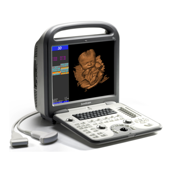
Chapter 3 Description of the System 3.1 Product Description The S6 is a professional, general purpose portable color Doppler diagnostic ultrasound system. It employs digital technology and fully exploits the potential of integrated circuits. The software is based on Linux system, which enhances the stability and efficiency while maintains the portability. -
Page 16: System Configuration
S6 Portable Digital Color Doppler Ultrasound System Service Manual 3.2 System Configuration Overview of the S6 System Front View P/N: 4720-0034-01A... - Page 17 S6 Portable Digital Color Doppler Ultrasound System Service Manual Side View Audio Out S-Video Socket Two USB Ports Ethernet Port VGA Port P/N: 4720-0034-01A...
-
Page 18: Applications
Power Input Socket Video Out 3.3 Applications The S6 system, with a wide range of probes available, is extremely versa- tile. This section introduces the applications that the S6 system is suitable for. Small organs (breast, thyroid, testicle and etc.) Vascular Abdomen (liver, spleen, cholecyst, kidney and etc.) -
Page 19: Operating Modes
Urology Musculoskeletal Note: The application fields are dependent on the probe in use. Warning! The S6 system is not intended for ophthalmic use or any use causing the acoustic beam to pass through the eye. 3.4 Operating Modes B Mode... -
Page 20: Scanning Modes
S6 Portable Digital Color Doppler Ultrasound System Service Manual Up B, Down M Up B, Down PW/CW (real time) Up B+COLOR,Down PW/CW Up B+COLOR, Down PW/CW (real time) Up B+COLOR, Down PW/CW (real-time refreshing) Color+M 3.6 Scanning Modes Electronic linear array scanning... -
Page 21: Spectral Doppler (Pw/Cw)
S6 Portable Digital Color Doppler Ultrasound System Service Manual Persistence range: from 0 to 95, may vary with the probes Line Density: 3 level adjustable (high/medium/low) Chroma: 13 different colors available Adaptive Image Fusion: 6 level adjustable Tissue Characteristic Index: adjustable from 1400 to 1700 Image Orientation: flip vertically and/or horizontally... -
Page 22: Archive And Backup
S6 Portable Digital Color Doppler Ultrasound System Service Manual 3.7.4 Archive and Backup 160G HDD (Hard Disk Drive) Image/Video Format: The system supports local format (PPM and CIN) and PC format (JPEG, BMP, TIF, AVI and WMV) and offers the function of conversion from local format to PC format. - Page 23 S6 Portable Digital Color Doppler Ultrasound System Service Manual M Mode Distance Time Slop HR (Heart Rate) LV (Left-Ventricular) measurements and calculations Available LV Calculation Methods: CUBE TEICHHOLZ GIBSON Mitral Valve Aortic Valve 4D Analysis Software Doppler Image Length measurements: straight line, perimeter of ellipse and any other arbitrary shapes.
- Page 24 S6 Portable Digital Color Doppler Ultrasound System Service Manual P/N: 4720-0034-01A 3-10...
-
Page 25: Principle Of The S6 System
This chapter provides the functional explanations of the electronics of the S6 system. 4.2 System Block Diagram Figure 4.1: Block Diagram of the S6 System The DBTR board has the following functionalities: Control the timing and band width of the emitted ultrasound; Amplify the variable gain of the echoes;... -
Page 26: Principle Of Probes
(e.g. LCD monitor). The computer system is the core control unit of S6. Following user in- structions from the keyboard, it controls the operating modes and adjusts the status of the system. -
Page 27: Functional Boards/Units Of The S6 System
The ECG and 4D motor units are also on this board. PC Motherboard: It is the core data processing unit of the S6 system. Power supply: ATX SMPS power supply. It provides stable power supply to the whole system (probes, host and LCD monitor). -
Page 28: Functional Block Diagram
S6 Portable Digital Color Doppler Ultrasound System Service Manual Monitor: 15 inch LCD Loudspeakers: Serve as Doppler audio device. 4.5.1 Functional Block Diagram Loudspeaker DBTR Board KBD board Monitor Loudspeakers Cable 7500-0820-XX 7500-0813-XX Voltage Conversion Board DBF Board Motherboard KEAA board... -
Page 29: Part List
S6 Portable Digital Color Doppler Ultrasound System Service Manual 4.6 Part List Part No. Name Quantity Description 7500-0826 Probe connection PCB board 7500-0820 DBTR Emission/Reception PCB board PCB board for receiving digital 7500-0821 beam forming and signal pro- cessing PCB board providing high volt-... - Page 30 S6 Portable Digital Color Doppler Ultrasound System Service Manual P/N: 4720-0034-01A...
-
Page 31: S6 Disassembly Instructions
S6 Disassembly Instructions This chapter contains step-by-step instructions on how to disassemble the S6 system for servicing. The flowchart (Figure 5.1, page 5-2) gives a graphic representation on the disassembly sequence and instructs the units that need to be removed during servicing. Additionally you can find infor- mation on connecting different parts inside the system in chapter 6. - Page 32 S6 Portable Digital Color Doppler Ultrasound System Service Manual Bottom Cover Back Cover MPC Metal Shield Power μ-SCAN Voltage Inversion MPC board Motherboard Fans Side IO Panel Supply Board Dongle KEAA Board Ultrasound Module Keyboard Cover DBHV DBTR Monitor Silicone Rubber...
-
Page 33: Bottom Cover
S6 Portable Digital Color Doppler Ultrasound System Service Manual 5.1 Bottom Cover Instructions Remove all the two pan head screws (M3×6) and four round head screws (M3×6) from the system, and pull the bottom cover away from the system to remove it. -
Page 34: Back Cover
S6 Portable Digital Color Doppler Ultrasound System Service Manual 5.2 Back Cover Item Description Quantity 1∼6 M3×6 screws Instructions Note: Screws 1∼4 are covered by rubbers. You need tweezers to remove them before removing the screws. Remove all the 6 screws shown in the picture above. - Page 35 S6 Portable Digital Color Doppler Ultrasound System Service Manual I. Loosen the back cover from the bottom side Pull Pull Press Press II. Loosen the back cover from the top side Note: Two hooks locks the back cover and the front frame together.
-
Page 36: Motherboard
S6 Portable Digital Color Doppler Ultrasound System Service Manual 5.3 Motherboard Connect Micro-Scan dongle here Figure 5.2: Motherboard P/N: 4720-0034-01A... -
Page 37: Keaa Board
S6 Portable Digital Color Doppler Ultrasound System Service Manual Item Description Item Description HDD SATA cable (3520-0506) Keyboard cable (3520-0508, CN2) SATA1 EKBM1 USB cable shield Audio cable (3520-0508, CN4) SOUT1 cable board USB cable for µ-SCAN dongle (3520-0510) USB2... - Page 38 S6 Portable Digital Color Doppler Ultrasound System Service Manual Figure 5.4: Cables Connected to KEAA Board Item Description Item Description 1∼4 Countersunk head screws 5∼10 Combination screws M3×6 M3×6 11, 16 Keyboard data cables KEAA main cables (3520- (3520-0505) J2 & J3...
-
Page 39: Hdd
S6 Portable Digital Color Doppler Ultrasound System Service Manual 5.5 HDD Item Description 1 &2 HDD SATA and power cables 3∼4 Combination screws M3×6 Instructions Remove the SATA and power cables (1∼2). Remove screws (3∼4), and pull the HDD horizontally along the arrow di- rectioin to remove it. -
Page 40: Voltage Conversion Board
S6 Portable Digital Color Doppler Ultrasound System Service Manual 5.6 Voltage Conversion Board Item Description 1∼4 Combination screws M3×6 Power connector for voltage conversion board 6∼9 LCD power wires 10∼11 Plastic screws Instructions Remove the four screws (1∼4). Remove the power connector (5) and remove the metal cover. -
Page 41: Fans
S6 Portable Digital Color Doppler Ultrasound System Service Manual 5.7 Fans Instructions There are three interconnected fans (only two are shown in the picture) inside the system. In order to remove them, you first need to remove these combination screws (M3×6) as indicated in the pictures, and remove the metal cover. -
Page 42: Mpc Board
S6 Portable Digital Color Doppler Ultrasound System Service Manual 5.8 MPC board Instructions I. Unfasten and remove the twelve combination screws (M3×6) from the metal shield. Remove eight pan head screws from the metal shield (indicated by trian- gles). II. Remove the four combination screws (M3×6) and take care to remove the MPC board. -
Page 43: Ultrasound Metal Shield
S6 Portable Digital Color Doppler Ultrasound System Service Manual 5.9.1 Ultrasound Metal Shield Figure 5.5: Remove the screws fastening the ultrasound metal shield Instructions Unfasten and remove all the seventeen combination screws (M3×6) and four pan head screws (M3×6) indicated above. -
Page 44: Ultrasound Module
S6 Portable Digital Color Doppler Ultrasound System Service Manual 5.9.2 Ultrasound Module Figure 5.6: Remove the cables attached to the ultrasound module Instructions Refer to Figure to remove the wires/cables attached to the ultrasound module. Refer to Figure to remove the two combination screws (M3×6, indicated by triangles) and the four pan head screws (M3×6, indicated by circles). - Page 45 S6 Portable Digital Color Doppler Ultrasound System Service Manual Viewed from switching power supply side Viewed from HDD side Figure 5.7: Remove the six screws P/N: 4720-0034-01A 5-15...
-
Page 46: Power Unit
S6 Portable Digital Color Doppler Ultrasound System Service Manual 5.10 Power Unit Instructions Remove the eight combination screws (M3×6) indicated in the above pic- tures. Note that the two pictures at the lower half are the view from the bottom; the power supply (the gray box) and the mains power switch are to be removed as one unit. -
Page 47: Keyboard Assembly
S6 Portable Digital Color Doppler Ultrasound System Service Manual 5.11 Keyboard Assembly Viewed from underneath Instructions Lift off and remove the keycaps indicated in the picture. Remove the four screws (indicated with triangles) from the keyboard cover. Note: These screws are covered by rubbers. You need tweezers to remove them before removing the screws. -
Page 48: Lcd Assembly
S6 Portable Digital Color Doppler Ultrasound System Service Manual 5.12 LCD assembly Instructions I. Remove the 2 Coun- tersunk head screws (M3×8) from ultrasound module bracket. II. Remove the 20 combination screws (M×6) fastening the ultrasound module bracket. Carefully detach the front frame from the ultrasound mod- ule bracket. - Page 49 S6 Portable Digital Color Doppler Ultrasound System Service Manual III. To detach the ultrasound module bracket from the LCD, remove the 4 pan head screws (M3×4). 5.掀起LCD的一端,然后将LCD信号线从支架中取出来如下图所示; Gently lift up the LCD from one side, and pull the LCD signal cable out through the ultrasound bracket.
- Page 50 S6 Portable Digital Color Doppler Ultrasound System Service Manual P/N: 4720-0034-01A 5-20...
-
Page 51: Wiring Instructions
S6 Portable Digital Color Doppler Ultrasound System Service Manual Chapter 6 Wiring Instructions 6.1 Introduction This chapter contains information for wiring inside the system. Section gives the general information and precautions for connecting miscellaneous parts/units. Section includes details on how to make each connection in the correct way. -
Page 52: Wiring In The System Level
S6 Portable Digital Color Doppler Ultrasound System Service Manual 6.2 Wiring in the System Level Please also refer to the schematic diagram attached in appendix of this service manual for connection. Refer to table on page to find the part numbers of the main PCB boards . - Page 53 S6 Portable Digital Color Doppler Ultrasound System Service Manual EKBM1 LVDS SATA2 SATA1 Figure 6.1: Connectors on the PC motherboard (2101-0008) P/N: 4720-0034-01A...
-
Page 54: Detailed Connection Instructions
S6 Portable Digital Color Doppler Ultrasound System Service Manual 6.3 Detailed Connection Instructions 6.3.1 Control Cable for Keyboard Unit (3520-0501) Connection Instructions: There are two identical control cables, both of them are connected in the same way. Connect CN1 to XS1 or XS2 on the KBD board. Connect CN2 to keyboard small board which is attached to the KBD board with screws. -
Page 55: Connection Cable For Loud Speakers (3520-0504)
S6 Portable Digital Color Doppler Ultrasound System Service Manual Connection Instructions: Connect CN1 to XS3 on the keyboard. Connect CN2 to the trackball (keep the white wire upwards.) Avoid inserting the connectors by force. 6.3.4 Connection cable for loud speakers (3520-0504) -
Page 56: Sata Cable For Hdd (3520-0506)
S6 Portable Digital Color Doppler Ultrasound System Service Manual 6.3.6 SATA cable for HDD (3520-0506) To PC motherboard To HDD SATA1 Connection Instructions: Connect CN1 to the SATA socket on the motherboard. Connect CN2 to the SATA socket on the HDD. To disconnect CN1, press the metal tab and re- lease the connector gently. -
Page 57: Cables Connecting Keyboard And Motherboard
S6 Portable Digital Color Doppler Ultrasound System Service Manual 6.3.8 Cables Connecting Keyboard and motherboard (3520-0508) Signal GND Audio L Audio R GND POWSWL POWSWR GND KBDATA KBCLK GND Color Black Violet Brown NC Green Green Blue Orange Black Connection Instructions: Connect CN1 to XS2 on the KEAA board. -
Page 58: Usb Cable For Μ-Scan Dongle(3520-0511)
S6 Portable Digital Color Doppler Ultrasound System Service Manual Connection Instructions: Connect CN1 to USB2 on the motherboard. Make sure to connect in the correct direction: the vacant hole on CN1 corresponds to the single-pin side of USB2. Connect CN3 to the GND pin on the motherboard. Connect CN2 to the DBF board. -
Page 59: Ecg Internal Connection Cable (3520-0513)
S6 Portable Digital Color Doppler Ultrasound System Service Manual 6.3.13 ECG internal connection cable (3520-0513) Signal Color shield green brown black yellow Connection Instructions: Connect CN1 to J14 on the DBF board and CN2 to the ECG connector on the back panel. -
Page 60: Main Power Cables From Smps (3520-0520)
S6 Portable Digital Color Doppler Ultrasound System Service Manual 6.3.16 Main power cables from SMPS (3520-0520) P/N: 4720-0034-01A 6-10... -
Page 61: Install And Update The System Software
7.1 Introduction The software design takes a significant part in the development of the whole system. The S6 system utilizes Linux platform, and the programs are written in C. Thanks to innovative algorithms employed in the system, most of the complicated tasks, such as data acquisition and data manage- ment, are performed through software. -
Page 62: Applicable Models
S6 Portable Digital Color Doppler Ultrasound System Service Manual 7.2 Applicable Models Instructions in this chapter are applicable to the models of S6 series and S6 series. 7.3 Update Files Two update files, a main file (adata file) and a control file (asecure file), are sent by the R&D department of SonoScape. -
Page 63: Non-Kernel Level Update Instructions
S6 Portable Digital Color Doppler Ultrasound System Service Manual Figure 7.1: System Information Window Method 2: The control number is also the serial number of the DBF board. You will need to disassmeble the system to find it, so use this method only if you are unable to start up the system. -
Page 64: Non-Kernel Level Software Update Procedures
S6 Portable Digital Color Doppler Ultrasound System Service Manual 7.4.2 Non-kernel Level Software Update Procedures 1. Plug the USB disk drive with update files into the USB port of the system. 2. Boot up the system, wait until the EXAM screen appears. -
Page 65: Upgrade Kernel And Software
S6 Portable Digital Color Doppler Ultrasound System Service Manual 7.5 Upgrade Kernel and Software 7.5.1 Upgrade Using USB Boot-up Disk Use the USB boot-up disk to upgrade the system if either of the following two cases is true: 1. The system is to be upgraded from versions older than 2.0.0.16 to 2.0.0.16 or later. - Page 66 S6 Portable Digital Color Doppler Ultrasound System Service Manual 7.5.3.2 BIOS Setup 1) Select Hard Disk Drives under Boot tab. BIOS SETUP UTILITY Main Advanced PCIPnP Boot Boot Security Chipset Exit Specifies the Boot Settings Boot Device Priority Sequence ► Boot Settings Configuration ►...
- Page 67 S6 Portable Digital Color Doppler Ultrasound System Service Manual BIOS SETUP UTILITY Main Advanced PCIPnP Boot Boot Security Chipset Exit Specifies the Boot Settings Boot Device Priority Sequence ► Boot Settings Configuration ► Boot Device Priority ► Hard Disk Drives ►...
- Page 68 S6 Portable Digital Color Doppler Ultrasound System Service Manual Figure 7.2: Upgrade dialog 2. The installation starts immediately. It will take 7 to 10 minutes to complete. Attention! If the installation fails double check the following prerequi- sites: • All boot up files and the kernel files should be intact.
- Page 69 find the control number for your system. b. Start up the S6 system, plug in the USB disk when the EXAM screen appears. c. Press these keys successively: Shift, E and Menu. The system will prompt for a password.
-
Page 70: Activate The Micro-Scan Function
Copy the Keypass file from PC to the root directory of a USB disk. c. Remove any removable USB drives if any, start up the S6 system. d. Plug in the USB disk drive with Keypass file when the EXAM screen appears. -
Page 71: System Functionality Tests
Warning! Only Service Engineers/Representatives trained to re- pair the S6 system and authorized by SonoScape should perform the system functionality tests. DONOT remove or replace any circuit boards while the system is powered on. -
Page 72: Speaker Test
S6 Portable Digital Color Doppler Ultrasound System Service Manual 2. A green mark means the corresponding test is a success. You may either quit or continue with the next test if necessary. 3. An illustration of data tables which reveal information on how the tested part is working. -
Page 73: Probe Id, Hv And Temp
S6 Portable Digital Color Doppler Ultrasound System Service Manual 8.2.8 Probe ID, HV and Temp This test includes three elements: 1. Identify the probe ID; 255 is displayed if no probe is connected. 2. It tests the functionalities of HV generator and HV regulator. -
Page 74: Run Test 8.2.1 (Speaker Test)
S6 Portable Digital Color Doppler Ultrasound System Service Manual Figure 8.1: System Information Window The Control Number shown hereis a unique number which varies from equipment to equipment; Software Version indicates the current version number which will be updated with system upgrade. -
Page 75: Run Tests From 8.2.2 And 8.2.9
S6 Portable Digital Color Doppler Ultrasound System Service Manual 8.3.2 Run Tests from 8.2.2 and 8.2.9 a) Move the cursor to the check box next to “System Memory", or any other test items mentioned from 8.2.2 to 8.2.9, and press SET key. You can also check the “Select all”... -
Page 76: Key Simulation Test
S6 Portable Digital Color Doppler Ultrasound System Service Manual 8.4 Key Simulation Test After clicking the Key Simulation button, the system enters the key simu- lation test. The interface simulates the user keyboard (refer to the figure below). All keys, flip switches and TGC sliders can be tested. - Page 77 S6 Portable Digital Color Doppler Ultrasound System Service Manual it is recommended to turn off the Ethernet by setting ezNetwork to off to reduce startup time. Notes: The network setting can also be configured at the DICOM setting interface (under the system menu).
- Page 78 S6 Portable Digital Color Doppler Ultrasound System Service Manual P/N: 4720-0034-01A...
-
Page 79: Supported Peripherals
C. USB 2.0 removable disk D. Thermal printer When connecting the device A or B to the S6 system, both the device and the ultrasound system must be properly configured before they are opera- tional. Other devices listed above are ready to use after being connected to the S6 system, no configuration is required. -
Page 80: Network Printer Installation
2.0.2.0 or higher 9.3.2 Configurations Before using the network printer, both the printer and the S6 system must be properly configured through the printer setting interface on a PC and/or printer control panel. This section gives instructions on how to install HP K5400DN and HP CP1515N printers, installations for other models should follow similarly. - Page 81 Chapter 1 (continued) Printhead latch Printheads Top cover Printhead latch S6 Portable Digital Color Doppler Ultrasound System S8 Portable Digital Color Doppler Ultraso Top cover Service Manual Control panel Control panel For more information about interpreting control-panel lights, see Control-pan 9.3.2.1 HP K5400DN Installation Procedures...
- Page 82 2、 用网线把打印机和计算机连接,打开打印机电源开关。等 3 分钟左右 按下打印机中网页打印的图标,打印机会打印出一个 IP 地址。如图所 S6 Portable Digital Color Doppler Ultrasound System 示:其 IP 为 169.254.103.148(IP 为随机分配) Service Manual Figure 9.2: Printer configuration page 3、 把随机分配的 IP 设置成指定 IP 192.168.254.183,设置方法如下: (1) 把计算机的 IP 置成 169.254.103.55,把打印机之前打印出来的 IP 169.254.103.148 输入 IE 浏览器,打开打印机设置网页,如...
- Page 83 Suivez les instructions à l’écran. 1. Connect the printer to the S6 system, turn on the printer. stale el software. Siga las instrucciones que aparecen en la pantalla. 2. On the control panel menu, press OK.
- Page 84 S6 Portable Digital Color Doppler Ultrasound System 2.7.2.5.2 Set Printer Service Manual Printer Driver: Supports HP printer driver. 2. Insert the USB drive and start up the ultrasound system. Enter System Setting, select Set Printer (see below).
-
Page 85: Network Connection With Pc
4. Otherwise review the IP setting of the ultrasound system, and/or re- install the printer driver. 9.3.3 Network Connection with PC Network connection between the S6 system and a PC can be achieved by either direct connection or indirect connection through router. P/N: 4720-0034-01A... - Page 86 4. Change the computer’s workgroup to "MSHOME" (Right click on My Computer icon, click Properties-Computer Name-Change.) 5. Connect the S6 system to the router with an Ethernet cable com- plying with T568B standard. Turn on the S6 system, wait until the EXAM screen appears (It takes about 5 minutes).
- Page 87 Computer icon, click Properties-Computer Name-Change.) 4. Connect the S6 system to the PC with a cross over cable. 5. Turn on the S6 system, wait until the EXAM screen appears (It takes about 5 minutes). Now open the Network Place window on the PC, the S6 system should have been shown as a computer named "SonoXXX".
- Page 88 S6 Portable Digital Color Doppler Ultrasound System Service Manual P/N: 4720-0034-01A 9-10...
-
Page 89: System Troubleshooting
10.2 Preparation 1. The user and service manuals for the S6 system should be thoroughly read before troubleshooting the equipment. All the warnings and cautions should be thoroughly read and properly understood. -
Page 90: Functional Check
10.3.1 Basic Functional Tests The basic functional tests with the expected results are described below. 1. Connect a probe, take L743 for example, to the S6 system. 2. The supported diagnostic modes illustrated as large icons are dis- played on the screen. Choose a diagnostic mode to start the real time scanning. -
Page 91: Functional Test For Critical Parts
S6 Portable Digital Color Doppler Ultrasound System Service Manual 5. Press M key to enter M mode, press UPDATE key to ensure that the system is working properly in M mode. Make sure that TGC, depth and power control are adjustable. Consult the user manual, if you do not know how to adjust these parameters. -
Page 92: Common Problems And Service Instructions
S6 Portable Digital Color Doppler Ultrasound System Service Manual 10.3.2.3 Motherboard The computer Motherboard is the central control unit of the S6 system, any faulty part or any faulty connection/contact will cause malfunction of the whole system. Ensure that all the connections/contacts with power supply, RAM, SATA connector, and etc. -
Page 93: Repairing Procedures
S6 Portable Digital Color Doppler Ultrasound System Service Manual Attention! After the system is powered on, if it shows abnormal startup screen or enters a diagnostic mode even without user’s inter- vention, it is likely that the keyboard is not working properly. -
Page 94: Problem Analysis
S6 Portable Digital Color Doppler Ultrasound System Service Manual 2. If you are uncertain about which component causes the problem, re- place them one by one and re-test after each replacement until the problem is solved. Replacing all the components before re-test is NOT recommended. - Page 95 S6 Portable Digital Color Doppler Ultrasound System Service Manual Startup Problems Problem Symptoms Suggested Solutions Check the following items: the power cord is correctly connected; the mains power switch There is no response after on the back panel is switched on; the input Unable to turn the pressing the power button.
- Page 96 S6 Portable Digital Color Doppler Ultrasound System Service Manual Startup Problems: continued from previous page Symptoms Problem Suggested Solutions The screen turns brown, displaying the following Restart the system several times to check if messages after startup: the same problem occurs.
- Page 97 S6 Portable Digital Color Doppler Ultrasound System Service Manual Operating Problems Problem Symptoms Suggested Solutions Replace the probe or try another one. Check for bad contacts and cold soldered At the EXAM screen, the di- Diagnostic mode joints on the probe board and the DBTR agnostic mode icons of a icons are flashing.
- Page 98 S6 Portable Digital Color Doppler Ultrasound System Service Manual Operating Problems: continued from previous page Symptoms Problem Suggested Solutions System crashes frequently. System crashes Sometimes gain poten- frequently It’s most likely caused by the DBHV board tiometers are not working gain knobs are malfunction.
- Page 99 S6 Portable Digital Color Doppler Ultrasound System Service Manual Operating Problems: continued from previous page Symptoms Problem Suggested Solutions Only central area of about Shadows on both 40 degrees is shown in the If other probes are working properly on the sides of the real ultrasound image;...
- Page 100 S6 Portable Digital Color Doppler Ultrasound System Service Manual Operating Problems: continued from previous page Symptoms Problem Suggested Solutions Test with an external VGA monitor. If no The displayed images gets Distorted display problem is shown, this implies that the moni- shrunk, scaled or distorted.
- Page 101 S6 Portable Digital Color Doppler Ultrasound System Service Manual Operating Problems: continued from previous page Symptoms Problem Suggested Solutions After being in Freeze mode several hours, system is not responding to the FREEZE key, or any other keyboard inputs. System freezes...
- Page 102 S6 Portable Digital Color Doppler Ultrasound System Service Manual P/N: 4720-0034-01A 10-14...
-
Page 103: System Maintenance
The backups can be saved to a CD/USB disk. Please follow these procedures to make backups: 1. Connect a writable CD/USB disk to the S6 system. 2. Enter the file manager window. 3. Click Patient Folder or General Folder icon to open it. - Page 104 Attention! For disposal of the equipment, hand it over to SonoScape or a local representative of SonoScape! Follow the procedures below to clean the system monitor, the keyboard and the outer surfaces of the equipment: 1.
-
Page 105: Probe Maintenance
S6 Portable Digital Color Doppler Ultrasound System Service Manual 11.3 Probe Maintenance The illustrations of a linear array probe and a convex array probe are shown below, • The probe is very sensitive to vibrations, handle the probe with care to prevent any collision damage. -
Page 106: Cleaning And Disinfecting Probes
S6 Portable Digital Color Doppler Ultrasound System Service Manual 11.4 Cleaning and Disinfecting Probes Warning! • Disconnect the probe from the host before cleaning or disinfecting. • When cleaning or disinfecting the probe, do not immerse it beyond the binding line. -
Page 107: A Make A Bootable Usb Key
A. Turn on the PC, enter BIOS setup; set the first boot device to optical drive. Insert the SonoScape upgrade CD. Save BIOS setting and turn off the system. B. It’s strongly recommended to disconnect any removable disk drives (thumb drive and external hard drive) right now. - Page 108 S6 Portable Digital Color Doppler Ultrasound System Service Manual P/N: 4720-0034-01A...
-
Page 109: B Cables & Wires Inside The System
S6 Portable Digital Color Doppler Ultrasound System Service Manual Appendix B Cables & Wires Inside the System The figure shown on the next page can be taken as reference for wiring or assem- bling. P/N: 4720-0034-01A... - Page 111 S6 Portable Digital Color Doppler Ultrasound System Service Manual P/N: 4720-0034-01A...
Need help?
Do you have a question about the S6 and is the answer not in the manual?
Questions and answers