Table of Contents
Advertisement
Quick Links
About This Manual
P/N: 4710.01486A01
Product Model: E1
Release Date: January, 2018
Copyright © 2018 SonoScape Medical Corp. All rights reserved.
Statement
SonoScape Medical Corp. (hereinafter called SonoScape) owns the intellectual property rights to
this manual, and also maintains the contents of this manual as confidential information. This manual
is a reference for the operation, maintenance and cleaning of this product and does not convey any
license under the patent rights of SonoScape, nor the rights of others.
This manual contains the information protected by copyrights or patents. Reproduction, amendment
or translation of this manual in any manner whatsoever without the written permission of SonoScape
is strictly prohibited.
All information contained in this manual is believed to be correct. SonoScape shall not be liable for
errors contained herein or for incidental or consequential damages in connection with the furnishing,
performance or use of this manual. SonoScape does not assume any liability arising out of any
infringements of patents or other rights of third parties.
This manual is based on the maximum configuration and therefore some contents may not apply to
your product.
This manual is subject to change without prior notice and legal obligation.
Manufacturer's Responsibility
SonoScape is responsible for the effects on safety, reliability and performance of this product, only if
all the following requirements are met.
●
A ll installation operations, expansions, changes, modifications and repairs of this product are
conducted by SonoScape authorized personnel .
●
The use or application of the product or the use of parts or accessories is approved by
SonoScape.
●
The electrical installation of the relevant room complies with the applicable national and local
requirements .
●
The product is used in accordance with the instructions for use.
Documentation
SonoScape provides the documentation consisting of various manuals:
●
The basic user manual (this manual) describes the basic functions and operating procedures of
the system.
Advertisement
Table of Contents

Related Manuals for Sonoscape E1


Summary of Contents for Sonoscape E1
- Page 1 SonoScape is strictly prohibited. All information contained in this manual is believed to be correct. SonoScape shall not be liable for errors contained herein or for incidental or consequential damages in connection with the furnishing, performance or use of this manual.
- Page 2 Address: 4/F, 5/F, 8/F, 9/F & 10/F, Yizhe Building, Yuquan Road, Nanshan, Shenzhen, 518051, Guangdong, China Tel: +86 755 2672 2890 Fax: +86 755 2672 2850 http://www.sonoscape.com E-mail: sonoscape@sonoscape.net EU Representative: SonoScape Europe S.r.l. Address: Via Luigino Tandura, 74-00128 Rome, Italy Tel: +39 06 508 2160 Fax: +39 06 508 4752 http://www.sonoscapeurope.com...
-
Page 3: Table Of Contents
Contents 1 S afety ............................1 1.1 Intended Use ..........................2 1.2 Safety Precautions ........................2 1.2.1 Electrical Safety ......................2 1.2.2 Mechanical Safety ......................4 1.2.3 Accessories Caring ......................4 1.2.4 Biohazard Considerations .....................5 1.3 Acoustic Power Principle ......................5 1.3.1 Biological Safety......................6 1.3.2 ALARA .........................6 1.3.3 Mechanical and Thermal Indices ..................6 1.3.4 Probe Surface Temperature Limits ................7 1.3.5 Imaging Functions that Change Acoustic Output ............8... - Page 4 Contents 3.2.3 Installing/Removing the Battery .................26 3.2.4 Status Indicator ......................27 3.3 Powering On/Off the System....................28 3.3.1 To Power On the System .....................28 3.3.2 To Activate Screen Saver ....................28 3.3.3 To Enter the Standby Mode ..................28 3.3.4 To Power Off the System ....................29 3.4 Adjusting the Brightness of the Monitor ................29 3.5 Connecting the Probe ......................29 3.6 Connecting the Peripheral Device ..................29...
- Page 5 Contents 4.9 Help Settings .........................65 4.10 Defining System Defaults ....................65 4.10.1 Loading System Defaults ..................65 4.10.2 Creating System Defaults ..................66 4.10.3 Exporting or Importing System Defaults ..............66 4.11 Viewing System Information ....................67 5 P reparing for an Exam ......................69 5.1 Acquiring Patient Information ....................70 5.1.1 Beginning a New Patient ....................70 5.1.2 Retrieving Archived Information ................72 5.1.3 Using DICOM Worklist ....................73...
- Page 6 Contents 7.1.3 Auto Optimization.......................95 7.1.4 Harmonic Imaging .....................96 7.1.5 Panoramic Imaging .....................96 7.2 Magnifying an Image ......................97 7.2.1 Filling the Full Screen....................97 7.2.2 Magnifying the Whole Image ..................98 7.2.3 Magnifying the ROI ....................98 7.3 Freezing an Image .........................99 7.4 Using Cine ..........................99 7.4.1 Reviewing Cine ......................99 7.4.2 Cutting Cine ........................99 7.5 Annotations and Body Marks ....................100...
- Page 7 Contents 9.8 DICOM Queue ........................117 10 P robes and Biopsy Brackets .................... 119 10.1 Probe ..........................120 10.1.1 Available Probes......................120 10.1.2 Probe Usage ......................121 10.1.3 Cleaning the Probe ....................123 10.1.4 Disinfecting or Sterilizing the Probe ..............124 10.1.5 Sterilizing the Probe....................127 10.1.6 Disinfecting and Sterilizing the Probe Cable ............127 10.1.7 Storage and Transportation ..................128 10.2 Biopsy ..........................129 10.2.1 Available Biopsy Brackets ..................129...
- Page 8 Contents B.1 Electromagnetic Emissions ....................142 B.2 Electromagnetic Immunity ....................142 B.3 Recommended Separation Distances between Portable and Mobile RF Communications Equipment and the Equipment ....................145 Appendix C In Situ, Derated, and Water Value Intensities ..........146 Appendix D Recommended Coupling Gel, Cleaner and Disinfectant ......147 D.1 Coupling Gel ........................147 D.2 Cleaner ..........................148 D.3 Disinfectant .........................149 Appendix ...
-
Page 9: Afety
1 S afety This chapter describes the important information for operating this system. To ensure the safety of both operator and patient, please read the relevant details in this chapter carefully before using this system. You should be thoroughly familiar with the precautions provided in this manual. Otherwise, the manufacturer is not responsible for the effects on safety, reliability and performance of the system. -
Page 10: Intended Use
1 Safety 1.1 Intended Use The system is intended for the following applications: Fetal, Abdominal, Pediatric, Small Organ (breast, testes, thyroid), Cephalic (neonatal and adult), Trans-rectal, Trans-vaginal, Peripheral Vascular, Cerebral Vascular, Musculo-skeletal (Conventional and Superficial), Cardiac (pediatric and adult), OB/Gyn and Urology. The system also provides the measurement and calculation packages used for clinical diagnosis purposes. - Page 11 1 Safety The video printer should be connected to the specific interface by using the cable ● provided by the manufacturer. Otherwise, electrical shock may occur. ● Within the environment that is 1.8 meters (6 feet) around a patient, connect peripherals to the auxiliary power outlet which is capable of isolation protection;...
-
Page 12: Mechanical Safety
1 Safety Accessory equipment connected to the analog and digital interfaces must be certified ● according to the respective EN/IEC standards (for example, EN/IEC 60950 for data processing equipment and EN/IEC 60601-1 for medical equipment). Furthermore, all configurations shall comply with the system standards EN/IEC 60601-1. Do not use an endocavitary probe on the body surface of a patient. -
Page 13: Biohazard Considerations
1 Safety Use the legally marketed coupling gel in accordance with relevant local regulations. ● Read and understand all precautions in the relevant manual of the coupling gel before use. Prepare, use, store and dispose the cleaner, disinfectant and sterilant according to the ●... -
Page 14: Biological Safety
1 Safety 1.3.1 Biological Safety Diagnostic ultrasound is recognized as being safe, but the possibility of biological effects exists when using it in high exposure levels and long exposure times. Thus ultrasound should be used in a prudent manner to provide medical benefit to the patient. 1.3.2 ALARA It is required to practice ALARA when using ultrasound energy. -
Page 15: Probe Surface Temperature Limits
1 Safety Mechanical bioeffects are threshold phenomena that occur when a certain level of output is exceeded. The threshold level varies, however, with different types of tissue. The potential mechanical bioeffects varies with peak pressure and ultrasound frequency. The MI accounts for these two factors. -
Page 16: Imaging Functions That Change Acoustic Output
1 Safety The maximum surface temperature of the endocavitary probes is 43°C. To protect the patient against the harm of excessive temperature, the probe stops working automatically when its temperature reaches the limit. The surface temperature of the probe is displayed on the screen. - Page 17 1 Safety Symbol Meaning Alternating current Direct current Degree of IP protection Non-ionizing electromagnetic radiation. Manufacturer Date of manufacture Follow instructions for use Network Port USB Port Fragile AUDIO output Keep dry Maximum stacking limit of packages Maximum of two layers allowed for the system Keep this way upward Basic User Manual...
- Page 18 1 Safety Symbol Meaning Serial Number Use it in ventilated and dry indoor environment (for AC adaptor only) Rechargeable (for battery only) This symbol indicates that waste electrical and electronic equipment must not be disposed of as unsorted municipal waste and must be collected separately. Please contact an authorized representative of the manufacturer for information concerning the decommissioning of your equipment.
-
Page 19: Ystem Overview
2 S ystem Overview This system adopts advanced ultrasonic Doppler technologies. To ensure the performance and availability of this system, you should be thoroughly familiar with the operations of system components, the control panel, the key panel and the basic screen. -
Page 20: System Configuration
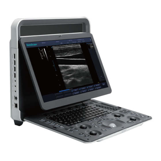
2 System Overview 2.1 System Configuration The standard system configuration mainly consists of the followings items: ● Main unit ● Probes Others: See the Packing List in the packaging box. ● 2.2 Physical Specifications ● LCD monitor: 15.6’’ color display ● System dimensions: approx. -
Page 21: Front Panel
2 System Overview 2.3.1 Front Panel Figure 2-2 Front View 1 Handle 4 Control panel 2 Probe holder 5 Indicators 3 LCD monitor 6 Release latch Basic User Manual... -
Page 22: Side View
2 System Overview 2.3.2 Side View Figure 2-3 Side Views 1 HDMI video output port 5 Print control port 2 USB port 6 S-Video output port 3 Audio output port 7 Network port (DICOM) 4 Audio input port 8 Power on/off button Basic User Manual... -
Page 23: Back View
2 System Overview 2.3.3 Back View Figure 2-4 Back View 1 Ventilation holes 5 Foot switch port 2 Cable hanger holder (optional) 6 AC adaptor port 3 Probe port 7 Video output port 4 ECG port (optional) 8 Grounding terminal 2.3.4 Bottom View Figure 2-5 Bottom View ... -
Page 24: Control Panel
2 System Overview 2.3.5 Control Panel 13 14 15 16 17 18 19 23 24 25 26 27 28 Figure 2-6 Control Panel Name Description Probe Select the corresponding exam type. Patient Enter the New Patient screen. Enter the Measurement Report screen. Report Review Display the Patient Exam List screen. - Page 25 2 System Overview Name Description Angle ● Adjust the flow direction in the PW mode. ● Adjust the arrow direction when the arrow annotation feature is activated. ● Adjust the measurement angle of the hip joint when performing the HIP measurement. Save images.
- Page 26 2 System Overview Name Description Freeze Freeze the image in the real time mode or restore the real time scan. Enter or exit the M mode. Enter or exit the PW mode. Reserved Enter the B mode. Auto/Gain ● Press it to automatically optimize an image. ●...
-
Page 27: Key Panel
2 System Overview Name Description Function ● These six function keys corresponds to the menu items Keys located at the bottom of the screen. ● Press it to select the corresponding menu item. ● Rotate it to set the selected menu item. 2.3.6 Key Panel Figure 2-7 Key Panel Name... - Page 28 2 System Overview Name Description Reverse an image left or right. Press it to enter panoramic mode Reserved Reserved Reserved Enable or disable the ECG feature. ● Delete the selected annotation, arrow or body mark when annotating an image. ● Delete the selected measurement marker and result when performing a manual trace measurement or other measurement.
-
Page 29: Basic Screen
2 System Overview 2.3.7 Basic Screen New hosp. XXXXX 19700101_203151 2014-11-06 10:39AM Sonoscape Dr Ng Kit Lenug MI 0.2 TIS 0.7 女 1/1P 4/20 Cine Frequncy Gray Map μScan Focus Area Compond NEXT 3.7-4.5 Line Density Chroma Persist Power Sector Width/Angle... - Page 30 T h i s p a g e i s i n t e n t i o n a l l y l e f t b l a n k .
-
Page 31: Reparing The System
3 P reparing the System System preparation is necessary before using the system. The preparation includes but is not limited to positioning and adjusting the system, connecting the probe and the peripheral devices. -
Page 32: Positioning The System
3 Preparing the System 3.1 Positioning the System Leave at least 20cm at the back and both sides of the system for ventilation. Otherwise, the temperature rise could cause failures. Place this system on a level surface. You can place the system on the trolley (sold separately) provided by manufacturer. For details on installing the system to the trolley, please refer to the relevant user manual. -
Page 33: Using The Battery
3 Preparing the System 3.2.2 Using the Battery Do not disassemble or alter the battery. Otherwise, there is a danger of explosion. ● Replace the battery with the type recommended by the manufacturer. ● ● Install/Remove the battery only when the system is powered off. ●... -
Page 34: Installing/Removing The Battery
3 Preparing the System Only use the battery if there is an emergency or no reliable AC power supply. It is ● recommended to use the AC supply instead of the battery. ● If you do not attempt to use the battery within 3 months, fully charge the battery and store it in the temperatures of -20°C to 45°C. -
Page 35: Status Indicator
3 Preparing the System 3.2.4 Status Indicator The status indicators are located on the control panel to indicate the battery charging and discharging statuses. When the system is powered on, you can move the cursor onto the battery icon by using the trackball to view the current battery capacity. The battery icon is displayed in the status bar. -
Page 36: Powering On/Off The System
3 Preparing the System 3.3 Powering On/Off the System ● Do not power off the system during system upgrade or a data transmission. ● An extra 30-60 seconds are needed for powering on the system if it is powered off in an abnormal way previously. ●... -
Page 37: To Power Off The System
3 Preparing the System 3.3.4 To Power Off the System button and select Shutdown on the pop-up menu to power off the system. Press the 3.4 Adjusting the Brightness of the Monitor Press Shift and the up/down arrow keys to adjust the brightness. 3.5 Connecting the Probe Disconnect the probe from the system after freezing an image or powering off the system. Otherwise, the system or the probe could be damaged. -
Page 38: Connecting The Printer
3 Preparing the System Ultrasound system Foot SW Used for printing Used for image freezing 3.6.2 Connecting the Printer Video printer, Window printer and USB printer recommended by the manufacturer can be connected to the system. ■ Video Printer Connect a video printer to the system. VIDEO OUT VIDEO INPUT PRINT... - Page 39 3 Preparing the System Set Default Printer to Windows Printer, input the IP address of the desired computer, and set the Printer Port Number to 6050. NOTE: • IP address of the computer and the system should be set in the same network segment.
- Page 40 T h i s p a g e i s i n t e n t i o n a l l y l e f t b l a n k .
-
Page 41: Ustomizing Your System
4 C ustomizing Your System The System Settings menu allows you to specify the operating status, system date and time, monitor brightness, etc. All your customized settings can remain even after rebooting the system. -
Page 42: General System Settings
4 Customizing Your System After you power on the system, the LCD monitor displays the Application Mode screen. Press the Setup key on the key panel to enter the System Settings menu. To make settings on the System Settings menu, ●... - Page 43 4 Customizing Your System Item Description Hospital Name Enter the institution’s name. End Exam Response Select the feature to be enabled after you press the End Exam key. Trackball Sensitivity Adjust the sensitivity for the trackball movement. A greater value brings about a higher sensitivity. Language Choose a system language for the user interface.
-
Page 44: Display Settings
4 Customizing Your System 4.1.2 Display Settings SystemSettings General General Display Save Biopsy Exam Preset Comment System Sleep Bodymark Screen Saver Wait Measure System Standby Report Width Ruler Auto Wait Peripheral Key Volume DICOM Volume Help Trackball Brightness&Colors Load Default Light color Ivory Keyboard &... - Page 45 4 Customizing Your System ■ Show Gallery Perform the following steps to perform a demonstration. Click Show Gallery to enter the Show Gallery screen, as shown in Figure 4-3. Show Gallery Down Bottom Play Interval 4 seconds Import Load Default Delete Exit Figure 4-3 Show Gallery Screen Load default demos or import demos from an external storage device.
-
Page 46: Save Settings
4 Customizing Your System 4.1.3 Save Settings SystemSettings General General Display Save Biopsy Exam Preset Comment prospective store retrospective store Freeze Store Bodymark Time Time Time Measure Report Save Format/Area Save Operation Area ImageArea+InfoBar Peripheral Cine Send image to DICOM storage DICOM Save Sound High... -
Page 47: Biopsy Settings
4 Customizing Your System Item Description S e n d c i n e t o Tick it, the system sends a cine to the DICOM storage server every DICOM storage time the cine is saved. Save Sound Set the volume level of the storage tone. 4.1.4 Biopsy Settings SystemSettings General... - Page 48 4 Customizing Your System Item Description Guide Line Type Select a type for the biopsy guideline. ● Set it to Line, and one biopsy guideline is displayed when performing a biopsy. ● Set it to Range, and two parallel biopsy guidelines are displayed when performing a biopsy.
-
Page 49: Exam Preset Settings
4 Customizing Your System 4.2 Exam Preset Settings SystemSettings L741 Probe Selection General Available Items Exam Preset Exam Preset Comment Bodymark C-Vascular Thyroid Breast Superficial Testicular Arterial Measure Report Peripheral DICOM Venous U-Nerve L-Nerve Help Selected Items Load Default About Delete C-Vascular Thyroid Breast Superficial... -
Page 50: Annotation Settings
4 Customizing Your System 4.3 Annotation Settings You can make annotation settings on the Tools and List tabs 4.3.1 Tools Settings SystemSettings General Tools List Exam Preset Comment Annotation Bodymark Select annotation Language English Measure Font size Medium Clear annotation while unfreezing image Report Peripheral Arrow... -
Page 51: List Settings
4 Customizing Your System ■ Arrow Annotation Settings Item Description Arrows size Set the size of the arrow. Clear arrow Enable or disable the auto-clear arrow feature after unfreezing an image. while ● Set it to ON, all arrows are cleared after you press the key in the unfreezing arrow annotation editing mode. -
Page 52: Body Mark Settings
4 Customizing Your System Perform the following steps. Select an exam type from the drop-down list beside Application. Select a text annotation library from the drop-down list beside Library. Add the desired text annotations in the selected library to the Annotation Selected list. -
Page 53: Measurement Settings
4 Customizing Your System − Click >> to add all the body marks in the selected body mark library to the Selected list. − Select a body mark in the Selected list and click < to remove it from the Selected list. - Page 54 4 Customizing Your System Item Description Measure Line Size Set the thickness of the measurement line. Dist. Dash Line Disp. Enable or disable the display of a dash line between two points when performing a distance measurement. Vel. Cross Line Disp. Enable or disable the display of a reticle between two points when performing a velocity measurement.
-
Page 55: Application Settings
4 Customizing Your System 4.5.2 Application Settings System Setting General General Application List Exam Preset Application Comment Bodymark Measurement Setting Auto/Man Trace Shortcut Key Measure Measure CUA/AUA Report Num 1 Add 1 week to EDD Peripheral Num2 Show EDD on screen DICOM Num3 Equation... - Page 56 4 Customizing Your System Item Description CUA/AUA Set to display CUA or AUA on the measurement report. CUA stands for Composite Ultrasound Age, and AUA stands for Average Ultrasound Age. Add 1 week to EDD Set to add one week to EDD. Show EDD on screen Set to display EDD in the measured result box.
- Page 57 4 Customizing Your System GA Table Measurement Author Deviation -2SD/+2SD Meas -2SD Mean +2SD Unit Meas[mm] -2SD[w+d] Mean[w+d] +2SD[w+d] Save&Exit Exit Figure 4-12 GA Table Growth Table Measurement Author Deviation -2SD/+2SD -2SD Mean +2SD Unit Age[w+d] -2SD[mm] Mean[mm] +2SD[mm] Save&Exit Exit Figure 4-13 Growth Table Basic User Manual...
-
Page 58: List Settings
4 Customizing Your System Select or input the Measurement, Author, Deviation and the corresponding Unit. Enter the gestational weeks and the values of measurement items in the table. Click Save&Exit to save the customized formula and exit. 4.5.3 List Settings System Setting General General... -
Page 59: Report Settings
4 Customizing Your System Select an exam type from the drop-down list beside Application. Select Caliper or Calc. Select an imaging mode in the List frame and select the collection item or measurement item that you wish to delete. Click Delete. 4.6 Report Settings SystemSettings Logo... - Page 60 4 Customizing Your System Item Description Title 1/2/3 Input the title name in the textbox and then set the font size using the drop-down list. Context Set the text font size. Title Set the font size of the headline. Subtitle Set the font size of the subtitle.
-
Page 61: Peripheral Devices Settings
4 Customizing Your System 4.7 Peripheral Devices Settings 4.7.1 Basic Settings SystemSettings General Basic Network Exam Preset Comment Video Output Bodymark Picture Area Area Measure CLOSE CVBS/S-VIDEO Report HDMI CLOSE Peripheral DICOM Printer Help Default Printer Windows Printer Load Default 192.168.1.101 Printer IP Address About Printer Port Number 6050... -
Page 62: Network Settings
4 Customizing Your System 4.7.2 Network Settings SystemSettings General Basic Network Exam Preset Comment Local Network Wireless Network Bodymark Enable Enable Measure Name State Level DHCP Static IP Mr.Wu Unconnected Report IP Address: 192.168.8.149 Peripheral Netmask: 255.255.255.0 DICOM 192.168.8.1 Default Gateway: Help Load Default Mac Address:... -
Page 63: Dicom Settings
4 Customizing Your System ■ Wireless Network Item Description Wireless Network Enable or disable the wireless network. Name Displays the name of the wireless network. State Displays the connection status of the wireless network. Level Displays the signal strength of the wireless network. Advance Click Advance to view the information of your current network, and make settings of your local network. - Page 64 4 Customizing Your System SystemSettings General DICOM Service Local Setting Exam Preset Comment Service List Bodymark Service Type Service Name AE Title IP Address Port Measure StoreSCP DicomStore 192.168.254.104 104 Report Peripheral DICOM Help Load Default About Edit Delete Ping Verify Apply Exit...
- Page 65 4 Customizing Your System Item Description IP Address Set the IP address of the DICOM storage server. Click Ping to test the connection. Port Number Set the port number of the DICOM storage server. Storage Commitment Set the storage commitment server of the DICOM storage Server server.
- Page 66 4 Customizing Your System ■ Storage Commitment Server Settings Add Dicom Service Service Type Storage Commitment Service Name AE Title Ping IP Address Verify Port Number Save Cancel Reset Item Description Service Name Set the server name of the DICOM storage commitment server.
- Page 67 4 Customizing Your System ■ Worklist Settings Add Dicom Service Service Type Worklist Service Name AE Title Ping IP Address Verify Port Number Study Type Query Date Maximum Results Save Cancel Reset Item Description Service Name Set the server name of the DICOM worklist server. AE Title Set the Application Entity (AE) title of the DICOM worklist server.
- Page 68 4 Customizing Your System ■ MPPS Settings Add Dicom Service Service Type MPPS Service Name AE Title Ping IP Address Verify Port Number Storage Server SR Server Save Cancel Reset Item Description Service Name Set the server name of the MPPS server. AE Title Set the Application Entity (AE) title of the MPPS server.
- Page 69 4 Customizing Your System ■ Query Retrieve Settings Add Dicom Service Service Type Query Retrieve Service Name AE Title Ping IP Address Verify Port Number Maximum Results Save Cancel Reset Item Description Service Name Set the server name of target ultrasound system that retrieve patient information of the DICOM query retrieve server.
- Page 70 4 Customizing Your System ■ Print Settings Add Dicom Service Service Type Print Service Name AE Title IP Address Ping Port Number Verify Print Advance Config Format Trim Priority Border White Medium Empty Image Paper White Orientation Color Portrait Grey Film Size Min Density Film Destination Max Density...
- Page 71 4 Customizing Your System Item Description Color Set the color of the image. Film Size Set the film size. Min. Density Set the minimum density level of the film. Film Destination Set the film destination. ● Set it to MAGAZINE, the image will be stored in a film magazine.
-
Page 72: Dicom Local Settings
4 Customizing Your System 4.8.2 DICOM Local Settings SystemSettings General DICOM Service Local Setting Exam Preset Comment Local Device Storage Setting Bodymark Station Name 2D Compression JPEG Measure AE Title 2D JPEG Quality Lossless Report Port Number Cine Compression JPEG Peripheral Timeout(sec) Cine JPEG Quality... -
Page 73: Help Settings
4 Customizing Your System ■ Storage Settings Item Description 2D Compression Set the compression format of the image. 2D JPEG Quality Set the compression quality of the image. Cine Compression Set the compression format of the cine. Cine JPEG Quality Set the compression quality of the cine. -
Page 74: Creating System Defaults
4 Customizing Your System Click Yes to load the system default. Click Cancel to cancel loading default settings, or click Delete to delete the selected default settings. 4.10.2 Creating System Defaults Click New, and the name of the new default settings will be shown on the Load tab. If the name of the new default settings already exists, you can click Replace to replace the existing default settings. -
Page 75: Viewing System Information
4 Customizing Your System 4.11 Viewing System Information You can view the current hardware version, the software version and the control number on the System tab. The control number is a unique number for the system. Basic User Manual... - Page 76 T h i s p a g e i s i n t e n t i o n a l l y l e f t b l a n k .
-
Page 77: Reparing For An Exam
5 P reparing for an Exam You can start an exam without entering any patient information. To avoid patient identification errors, you should always verify the identification information with the patient. -
Page 78: Acquiring Patient Information
5 Preparing for an Exam 5.1 Acquiring Patient Information You can acquire the patient information in the following ways. ● Create new patient information. ● Retrieve archived patient information. Receive patient information using the DICOM worklist. ● Retrieve patient information from other ultrasound systems. ●... - Page 79 5 Preparing for an Exam Patient ID Enter the patient ID. The system will generate the patient ID automatically according to the current system time if this item is left blank. NOTE: The patient ID is an important identification. Once it is saved, you cannot modify it.
-
Page 80: Retrieving Archived Information
5 Preparing for an Exam NOTE: • You must enter the height and weight for the current patient when you select Cardiology as the exam type. BSA will be automatically calculated in accordance with the BSA set on the Measure menu. •... -
Page 81: Using Dicom Worklist
5 Preparing for an Exam Patient Exam List Last Name First Name Patient ID Reset Date 11/9/2017 11/9/2017 Patient Review Current Exam Patient ID Patient Name Birth Date Sex Exam Time Image Size Status New Patient 20150505 Mary Unknown 2015/05/05-16:04:03 40.82M PPS Screen DICOM Q/R DICOM Queue... -
Page 82: To Complete An Exam
5 Preparing for an Exam Select the desired patient information, and then click View to enter the Exam View screen. Select the desired exam, and then click Resume Exam to resume the exam. 5.2.3 To Complete an Exam Press the End Exam key on the control panel to end the current exam. Click Confirm on the pop-up dialog box to confirm to end the current exam. -
Page 83: Cquiring Images
6 A cquiring Images You can acquire images by optimizing the relevant parameters for clinical diagnosis. -
Page 84: Selecting A Probe And An Exam Type
6 Acquiring Images 6.1 Selecting a Probe and an Exam Type Once you power on the system, the system enters the real time B mode by default. You can press the Probe key to enter the Application Mode screen (as shown in Figure 6-1) and select the desired application mode. C-Vascular Thyroid Breast... -
Page 85: To Arrange The Presets Display
6 Acquiring Images User Pre-Set Menu Name Type Abdomen Part C-Vascular Save Exit Figure 6-2 User Pre-set Menu Screen Enter the name of the application preset in the Name textbox. Select the department and exam type from the Type and Part lists. Click Save to create the customized application preset. If the name of the application preset exists, you can click Yes in the pop-up dialogue box to replace it. -
Page 86: Acquiring B-Mode Images
6 Acquiring Images 6.2 Acquiring B-Mode Images B-mode imaging is intended to provide information of anatomical structure of soft tissue. 6.2.1 Entering B Mode The system enters B mode by default after you select a probe model and an exam type. You can press the B key on the control panel to enter B mode from other imaging modes. The basic screen in the B mode is displayed as follows: 7.5-10.5 14.0... - Page 87 6 Acquiring Images NOTE: You can adjust all parameters in the real time B mode, but can only adjust Rotation, Chroma, Gray Map and μScan in the frozen B mode. ■ Gain The B mode gain (2D gain) determines the amplifying factors for the received echoes and the brightness of the ultrasound image.
- Page 88 6 Acquiring Images ■ Depth Depth is used to adjust the distance over which the B-Mode image is anatomized. You can press the Depth switch to adjust the depth range of the 2D image and the size of image. NOTE: • The frame rate varies with the depth.
- Page 89 6 Acquiring Images Press the function key to select Gray Map. Rotate the function key to adjust the value. ■ Compound Imaging Compound imaging is used to acquire a series of overlapping image frames from substantially differing spatial directions and combining these images to reduce speckle and improve contrast resolution.
- Page 90 6 Acquiring Images Press the function key to select Sector Width. Rotate the function key to adjust the width or angle of the interest area. ■ Power Power is used to select the amount of ultrasound acoustic power produced by the probe in the B mode.
-
Page 91: Acquiring M-Mode Images
6 Acquiring Images ■ Steer Steer can be adjusted to change the direction of the acoustic beam when performing a real time mode by using the linear probes. To adjust the steer: Press the function key to select Steer. Rotate the function key to adjust the settings. NOTE: Only the linear probes are available when adjusting the steer. - Page 92 6 Acquiring Images M Line Figure 6-5 Inactivated B+M-Mode Imaging Screen Adjust the position of the M line by using the trackball. Press the Update key to activate the M mode. The B-mode image with a M line is displayed at the upper part of the screen and the M-mode image is displayed at the lower part of the screen after being activated, as shown in Figure 6-6.
-
Page 93: Optimizing M-Mode Images
6 Acquiring Images NOTE: Once the M mode is activated, you can move the trackball to stop the M trace and adjust the M line. The system continues tracing if the trackball is idle for more than 0.5s. Optimize M-mode image. For details, refer to Section 6.3.2 Optimizing M-Mode Images. - Page 94 6 Acquiring Images ■ Sweep Speed Sweep speed is used to set the sweep speed of the M trace. A faster speed is more suitable to view the motion. To adjust the sweep speed: Press the function key to select Sweep Speed. Rotate the function key to adjust the value.
-
Page 95: Acquiring Spectral Doppler Images (Optional)
6 Acquiring Images ■ Power Power is used to select the amount of ultrasound acoustic power produced by the probe in the real time M mode. To adjust the power: Press the function key to select Power. Rotate the function key to adjust the value. NOTE: Expose the patient to the lowest practical transmit power level for the shortest possible time to achieve a satisfactory diagnosis. - Page 96 6 Acquiring Images Spectral Doppler Line Sample Volume Gate Flow Cursor 2D Image Line-Pos SV-Size Figure 6-7 Inactivated B+PW Mode 1 Imaging Screen − The spectral Doppler line and the sample volume gate are used to locate the qualitative analysis on the image. − The flow cursor needs to be adjusted parallel to the flow when measuring the velocity.
- Page 97 6 Acquiring Images Y axis: frequency PW spectrum X axis: time Figure 6-8 PW-Mode Imaging Screen − X-axis is the time scale. − Y-axis is Doppler frequency scale, including positive and negative indicators. Press the Shift and left/right arrow keys to adjust the audio volume. Or, rotate the function key corresponding to Volume to adjust the audio volume.
-
Page 98: Optimizing Spectral Doppler Images
6 Acquiring Images Y axis: frequency X axis: time Figure 6-9 Inactivated B+PW Mode 2 Imaging Screen You can also adjust the position and angle of spectral Doppler line, the size of sample volume gate, and the direction of the flow cursor. Press the PW key to exit. 6.4.2 Optimizing Spectral Doppler Images After activating the PW mode, the imaging parameters display at the bottom of the LCD monitor. - Page 99 6 Acquiring Images ■ Scale Scale is used to adjust the velocity scale. You can press the Scale switch to adjust the value. NOTE: The value of wall filter may change with the scale value. ■ Baseline Baseline represents the position of zero velocity or frequency. The velocity range in one direction can be increased or decreased by adjusting the baseline.
- Page 100 6 Acquiring Images ■ Sweep Speed Sweep speed is used to set the sweep speed of the Doppler trace. The refresh speeds of the time scale and the frequency scale vary with the sweep speed. To adjust the sweep speed: Press the function key to select Sweep Speed. Rotate the function key to adjust the value.
- Page 101 6 Acquiring Images Press the function key to select Steer. Rotate the function key to adjust the settings. NOTE: Only the linear probes are available when adjusting the steer. ■ Simult Simult is used to synchronously display two real time scans in the B mode and the PW modes.
- Page 102 T h i s p a g e i s i n t e n t i o n a l l y l e f t b l a n k .
-
Page 103: Orking With Images
7 W orking with Images You can work with the acquired images by using the features provided by the system, such as the split screen display and annotations. -
Page 104: Imaging Features
7 Working with Images 7.1 Imaging Features 7.1.1 Imaging Reverse ● Press the key on the key panel to reverse the real time scan left or right. Press the key on the key panel to reverse the real time scan up or down. ●... -
Page 105: Auto Optimization
7 Working with Images 7.5-10.5 14.0 µS Figure 7-2 Quad-Split Screen Display Press the THI key on the control panel to enter the corresponding mode for the real ● time scan. Press the key on the control panel to freeze the real time scan only. ●... -
Page 106: Harmonic Imaging
7 Working with Images 7.1.4 Harmonic Imaging Harmonic Imaging (THI) uses the harmonic frequencies generated by tissue. The fundamental transmit frequency results in a harmonic frequency echo. The harmonic frequency received from the tissue is a multiple of the fundamental transmit frequency. The fundamental and any accompanying artifacts are missing from the harmonic frequency that the system receives. -
Page 107: Magnifying An Image
7 Working with Images Position the B-mode image to the desired scan position. Press the Pan key on the key panel to enter the inactivated Panoramic Imaging mode. Press the Update button on the control panel to enter the real-time panoramic imaging. -
Page 108: Magnifying The Whole Image
7 Working with Images NOTE: Exit the text annotation editing mode before performing this function. For details, refer to Section 7.5.1 Annotating an Image with Typed Words. Perform the following steps. Press the Z key on the key panel to magnify the imaging area, information bar, and general parameter area into full screen. -
Page 109: Freezing An Image
7 Working with Images 7.3 Freezing an Image Press the key on the control panel to capture an image in a real time scan, Cine is displayed at lower right corner of the screen, and the feature to be applied is also activated. For the setting, refer to Section 4.1.1 General Settings. -
Page 110: Annotations And Body Marks
7 Working with Images Rotate the function key corresponding to Set Last to select the end frame. Press the Cine key on the control panel to save the cut cine. 7.5 Annotations and Body Marks The annotation feature allows you to type an annotation or add an annotation from the predefined annotation library. -
Page 111: Body Mark
7 Working with Images Press the Arrow key on the key panel in any mode, and an arrow displays on the screen. Position the arrow to the desired place by using the trackball. Rotate the Angle knob to adjust the arrow angle if needed. Press the confirm key to confirm. -
Page 112: Ecg Module
7 Working with Images ■ To Delete a Body Mark If a body mark is being edited, press the Del key to delete the body mark on the current image. If a body mark has been edited and the system exits the editing status, you can first press the Body Mark key and press the Del key to delete it from the screen. - Page 113 7 Working with Images Yellow White Black Green Green Black IEC Standard AHA Standard Figure 7-4 Electrode Placement Make the relevant ECG settings. a. Press the Menu key on the key panel to activate the menu. b. Click ECG, and ECG parameters are displayed on the screen. c.
- Page 114 T h i s p a g e i s i n t e n t i o n a l l y l e f t b l a n k .
-
Page 115: Anaging Images/Data
8 M anaging Images/Data Images in this system include frame images and cine, you can save or review them after the acquisition. Meanwhile, images can also be backed up to a USB drive for future review if it is needed. -
Page 116: Storing An Image/Cine
8 Managing Images/Data 8.1 Storing an Image/Cine The following methods can be used to store images/cines. Before storing an image or a cine, set the storage time of cine, storage format of file, and pre-defined key for storage. For details, refer to Section 4.1.3 Save Settings. 8.1.1 Storing an Image Store an image as follows. - Page 117 8 Managing Images/Data − Click the icon to go to the previous or next clipboard page. − Click the icon to select all images. − Click the icon to export images to the DICOM server. − Click the icon to export images to a USB drive. −...
-
Page 118: Retrieving An Image
8 Managing Images/Data 8.2.2 Retrieving an Image Perform the following steps. Select the Patient key > Patient List > Patient View to enter the Patient View screen. Select the desired patient, and then click View to enter the Exam View screen. Select the desired exam, and click View Image to retrieve the image. 8.3 Backing up Data All data is saved to the system by default. -
Page 119: Importing Data To The System
8 Managing Images/Data 8.4 Importing Data to the System NOTE: • Only data generated by this system can be imported. • Ensure the current exam is completed before you import data. Otherwise, you may have a failure data import. Perform the following steps. Connect the USB drive to the system. - Page 120 T h i s p a g e i s i n t e n t i o n a l l y l e f t b l a n k .
-
Page 121: Orking With Dicom
9 W orking with DICOM DICOM (Digital Imaging and Communications in Medicine) is a standard created by National Electrical Manufacturers Association (ACR-NEMA) to regulate the distribution and viewing of medical images such as ultrasound images and cine. If the system is configured with the DICOM module, you can: ●... -
Page 122: Verifying Connectivity
9 Working with DICOM 9.1 Verifying Connectivity Perform the following steps. Connect the system to the local DICOM network server by using a network cable. Edit the relative settings for the local network and DICOM server. For details, refer to Section 4.7.2 Network Settings and Section 4.8 DICOM Settings. After the verification is successful, you can use the DICOM services. -
Page 123: Dicom Print
9 Working with DICOM 9.3 DICOM Print DICOM Print is used to send images to the DICOM print server for printing. You should properly connect the system to the print server and edit the relevant settings. For details, refer to Section 4.8 DICOM Settings. Choose the Patient ... -
Page 124: Query/Retrieve List
9 Working with DICOM WorkList Search Patient ID Last Name First Name Accession# Date 11/09/2017 11/09/2017 Only US Requested Procedure ID Reset WorkList Information Patient ID Patient Name Birth Date Sex Description Requested Procedure ID Accession# Date Time Select Start Exam Cancel Figure 9-1 WorkList Screen Perform the following steps. - Page 125 9 Working with DICOM Query/Retrieve List Patient ID Last Name First Name Query Patients 10/22/2017 10/22/2017 Date Accession# Only Us Reset Patients Patient ID Patient Name Birth Date Exams Last Exam Query Exams Exams Patient ID Accession# Exam Time Exam Size Retrieve Images Exam Type 0/0P...
-
Page 126: Mpps
9 Working with DICOM a. Move the cursor to the desired image or cine, and press the confirm key. Click the icon to go to the previous or the next page of the image and cine box. Click the icon to select all images or cines. b. -
Page 127: Storage Commitment
9 Working with DICOM PPS Screen Information Patient ID Patient Name BirthDate Description Start Time End time State Exit Append Discontinue Completed Figure 9-3 PPS Screen The PPS screen displays MPPS information about the current patient. − Click Discontinue to suspend the current exam. −... - Page 128 9 Working with DICOM DICOM Queue Patient ID Last Name First Name Type Reset 11/09/2017 11/09/2017 Date DICOM Queue Information Type Patient ID Patient Name Server Start Time Size Run State Status Details Exit Refresh All Select Resend Fail Resend Delete Figure 9-4 DICOM Queue Screen Perform the following steps.
-
Page 129: Robes And Biopsy Brackets
10 P robes and Biopsy Brackets You should become thoroughly familiar with the operations of the probe and biopsy bracket before using them. To ensure the performance of the probe and the biopsy bracket, you should periodically check, clean, disinfect and maintain them. -
Page 130: Probe
10 Probes and Biopsy Brackets NOTE: A general instruction for the probe and biopsy bracket is provided in this manual. For details, refer to the relevant manuals. 10.1 Probe This system supports a wide range of probes which make the system remarkably versatile. The schematic diagrams of probes are as follows. -
Page 131: Probe Usage
10 Probes and Biopsy Brackets 10.1.2 Probe Usage Use only the probes provided by the manufacturer. Otherwise, the system may not ● perform and an accident such as a fire may result. Use the probe carefully. If any part of the probe surface is scratched, immediately stop ●... - Page 132 10 Probes and Biopsy Brackets Swelling of the acoustic window material. ● Cracks or wear on the probe cable. ● Cracks on the probe connector or any other kinds of visible damage. ● ● Deformed pins or broken pins inside the probe connectors. ●...
-
Page 133: Cleaning The Probe
10 Probes and Biopsy Brackets 10.1.3 Cleaning the Probe To avoid electrical shock, disconnect the probe from the system before cleaning. ● To avoid potential disease transmission, you should wear sterile medical gloves and ● protective goggles while cleaning. Do not use the cleaner that contains sodium sulfate and/or sodium hypochlorite to ●... -
Page 134: Disinfecting Or Sterilizing The Probe
10 Probes and Biopsy Brackets 10.1.4 Disinfecting or Sterilizing the Probe There is a cleared list of sterilants and high-level disinfectants for use in processing ● reusable medical and dental devices on the FDA website. That list can be consulted to find agents that may be useful for probe disinfection. Please refer to the following URL for FDA-Cleared Sterilants and High Level Disinfectants: http://www.fda.gov/ MedicalDevices/DeviceRegulationandGuidance/ReprocessingofSingle-UseDevices/ ucm133514.htm. - Page 135 10 Probes and Biopsy Brackets Classification Definition Level of Disinfection Application Critical A device that enters Sterilization I n t r a o p e r a t i v e , normally sterile tissue b i o p s y u s e o r or the vascular system.
- Page 136 10 Probes and Biopsy Brackets Table 10-1 Recommended Method for Medium-level Disinfection Disinfectant Manufacturer Active Level for Active Contact Contact Ingredient Ingredient Type Period Spray/ <10 Isopropyl Isopropyl Wipe minutes alcohol alcohol T-spray II Pharm. Inc. Quat. Spray/ <10 Ammonia Wipe minutes T-spray...
-
Page 137: Sterilizing The Probe
10 Probes and Biopsy Brackets 10.1.5 Sterilizing the Probe You should sterilize the intraoperative, biopsy use probe or any probe that comes into contact with blood after each use. Perform the following steps. Clean the probe. For details, refer to Section 10.1.3 Cleaning the Probe. Sterilize the intraoperative probe as shown in Table 10-3. -
Page 138: Storage And Transportation
10 Probes and Biopsy Brackets Rinse the surfaces of the probe cable with fresh running water to completely remove the residual disinfectant. Dry the probe cable with a lint-free soft dry cloth. Table 10-4 Recommended Method for Medium-level Disinfection Disinfectant Manufacturer Active Level of Active... -
Page 139: Biopsy
10 Probes and Biopsy Brackets 10.2 Biopsy You should properly assemble and verify the biopsy bracket before performing a biopsy. Only use the biopsy bracket in conjunction with the probe provided by the ● manufacturer. Otherwise, the system and probe may be damaged, an accident such as a fire may result in the worst case. -
Page 140: Assembling The Biopsy Bracket
10 Probes and Biopsy Brackets Biopsy Available Available Biopsy Needle Application Bracket Model Probe Model NGB6V3 16G, 18G, 20G, 22G Intracavitary NGB6V1 16G, 18G, 20G, 22G Intracavitary NGBEC9-5 EC9-5 16G, 18G, 20G, 22G Intracavitary 10.2.2 Assembling the Biopsy Bracket ■ To Assemble the Surface Biopsy Bracket Tube Holder Biopsy Guide Tube Fixing Bracket Protrusion Perform the following steps. - Page 141 10 Probes and Biopsy Brackets Place the biopsy guide tube into the tube holder. Insert the biopsy needle into the tube. Unfold another probe sheath, and apply an appropriate amount of coupling gel to the inside of the sheath. Hold the probe attached with the biopsy bracket and unroll the sheath onto them. ■ ...
- Page 142 10 Probes and Biopsy Brackets Hold the probe and unroll the sheath onto the probe. Pull the probe sheath tightly over the face of the probe to remove wrinkles. Slide the inner part into the top housing and push forward until it clicks. Align the biopsy bracket with the orientation mark of probe.
-
Page 143: Preparing For A Biopsy
10 Probes and Biopsy Brackets Unfold another probe sheath, and apply an appropriate amount of coupling gel to the inside of the sheath. Hold the probe attached with the biopsy bracket and unroll the sheath onto them. 10.2.3 Preparing for a Biopsy Before and after using a rectal or transvaginal probe to perform a biopsy, you should clean and sterilize the probe and all the biopsy accessories. -
Page 144: Performing A Biopsy
10 Probes and Biopsy Brackets 10.2.5 Performing a Biopsy NOTE: Ensure the biopsy bracket is properly attached to the compatible probe and be verified before you perform a biopsy. Perform the following steps. Choose Setup > General > Biospy > Biopsy Guide Line, set Biopsy Angle and Guide ... -
Page 145: Cleaning The Biopsy Bracket
10 Probes and Biopsy Brackets Biopsy Needle Biopsy Enhanced Region Line Ultrasound Image Press the function key corresponding to SteerAngle and rotate the function key to adjust the angle of the biopsy enhanced region line. Angle a becomes more closely to 90°, and brightness of the biopsy needle becomes more stronger. -
Page 146: Storage
10 Probes and Biopsy Brackets Clean the biopsy bracket. For details, refer to Section 10.2.6 Cleaning the Biopsy Bracket. Sterilize the biopsy bracket as shown in Table 10-5 for the entire recommended soaking period. Rinse the bracket with running sterile water to completely remove the residual sterilant. -
Page 147: Ystem Maintenance
11 S ystem Maintenance To maintain the safety and functionality of the system, periodically perform the maintenance for the system and accessories. -
Page 148: Cleaning The System
11 System Maintenance To avoid electric shock and damage to the system, power off and unplug the system ● from the AC power outlet before cleaning. ● To maintain the safety and functionality of the system, maintenance must be performed at least once every year. Electrical safety tests must also be performed at regular intervals as specified by local safety regulations. -
Page 149: Maintenance Checks
11 System Maintenance 11.2 Maintenance Checks To maintain the safety and functionality of the system, the following maintenance checks must be performed by service personnel at least every 1 year. 11.2.1 Electrical Safety Integrity of power cable ● ● Protective conductor resistance ●... -
Page 150: Equipment Disposal
Any feedback or inquires concerning our product or services should be directed to the following address. Address: 4/F, 5/F, 8/F, 9/F & 10/F, Yizhe Building, Yuquan Road, Nanshan, Shenzhen, 518051, Guangdong, China Zip Code: 518051 Tel: +86 755 2672 2890 Fax: +86 755 2672 2850 E-mail: service@sonoscape.net Basic User Manual... -
Page 151: Appendix A Specifications
Appendix A Specifications Comply with EN 60601-1 (IEC 60601-1), Medical electrical equipment Part 1: General requirements for basic safety and essential performance EN 60601-2-37 (IEC 60601-2-37), Medical Electrical Equipment Part 2-37: Particular Requirements for the Basic Safety and Essential Performance of Ultrasonic Medical Diagnostic and Monitoring Equipment EN 60601-1-2 (IEC 60601-1-2), Medical Electrical Equipment Part 1-2: General requirements for basic safety and essential performance - Collateral... -
Page 152: Appendix B Emc Guidance And Manufacturer's Declaration
Appendix B EMC Guidance and Manufacturer’s Declaration B.1 Electromagnetic Emissions The equipment is intended for use in the electromagnetic environment specified below. The customer or the user of the EQUIPMENT should assure that it is used in such an environment. Emissions Test Compliance Electromagnetic Environment and Guidance RF emissions... - Page 153 Appendix B EMC Guidance and Manufacturer’s Declaration Immunity Test IEC 60601 Test Compliance Electromagnetic Environment and Level Level Guidance Electrical fast ±2 kV for power ±2 kV for power Mains power quality should be that of a typical commercial or hospital transient/burst supply lines;...
- Page 154 Appendix B EMC Guidance and Manufacturer’s Declaration Immunity IEC 60601 Compliance Electromagnetic Environment and Test Test Level Level Guidance Conducted RF 3Vrms 3 Vrms Portable and mobile RF communications equipment should be used no closer to any IEC 61000-4-6 1 5 0 k H z - 8 0 part of the EQUIPMENT, including cables, than the recommended separation distance R a d i a t e d R F...
-
Page 155: Recommended Separation Distances Between Portable And Mobile Rf Communications Equipment And The Equipment
Appendix B EMC Guidance and Manufacturer’s Declaration Immunity IEC 60601 Compliance Electromagnetic Environment and Test Test Level Level Guidance Field strengths from fixed transmitters, such as base stations for radio (cellular/cordless) telephones and land mobile radios, amateur radio, AM and FM radio broadcast and TV broadcast cannot be predicted theoretically with accuracy. -
Page 156: Appendix C In Situ, Derated, And Water Value Intensities
Appendix C In Situ, Derated, and Water Value Intensities All intensity parameters are measured in water. Since water absorbs very little acoustic energy, these water measurement represent a worst case value. Biological tissue does absorb acoustic energy. The true value of the intensity at any point depends on the amount and type of tissue and the frequency of the ultra-sound that passes through the tissue. -
Page 157: Appendix D Recommended Coupling Gel, Cleaner And Disinfectant
Appendix D Recommended Coupling Gel, Cleaner and Disinfectant NOTE: • Coupling gels, cleaners and disinfectants listed in this manual are recommended because of their chemical compatibility with product materials, not their biological effectiveness. For the biological effectiveness of a disinfectant, refer to the guidelines and recommendations of the disinfectant manufacturer, Association for Practitioners in Infection Control, U.S. -
Page 158: Cleaner
Appendix D Recommended Coupling Gel, Cleaner and Disinfectant Probe Model Applicable Inapplicable 2P1, 5P1, 10L1, C311, C321, C343, Aquasonic 100, Aquasonic Clear, Sterile Aquasonic, Clear Image/ C344, C351, C352, C361, C362, C511, Single, Sterile Ultraphonic Gel, C521, C541, C542, C543, C611, C612, Transonic gel, Clear Scanning Gel, C721, L541, L561V, L662V, L741, Multigel Gel... -
Page 159: Disinfectant
Appendix D Recommended Coupling Gel, Cleaner and Disinfectant D.3 Disinfectant Probe Model Applicable Inapplicable MPTEE Mini 7-4, MPTEE 7-4, MPTEE, MPTEE mini, C i d e x O P A M e t r i c i d e 2 8 , M e t r i c i d e 3 0 , 12C-ER Solution, Cidex,... -
Page 160: Appendix E Acoustic Output Data
Appendix E Acoustic Output Data Please consult the accompanying CD.
Need help?
Do you have a question about the E1 and is the answer not in the manual?
Questions and answers
Machine not communicating with printer because of the forgotten password