
Related Manuals for Carrier Idrofan 42NH


Summary of Contents for Carrier Idrofan 42NH
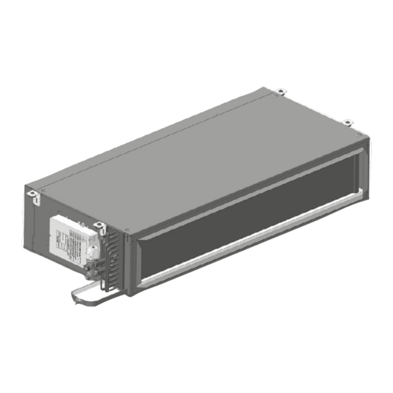
- Page 1 I N S TA L L AT I O N, O P E R AT I N G A N D M A I N T E N A N C E I N S T R U C T I O N S DUCTED FAN COIL UNITS 42NL &...
-
Page 3: Table Of Contents
CONTENTS 1 - PRECAUTIONS ............................... 11 1.1 - Operating limits ............................11 1.2 - Clearances required ............................ 11 1.3 - Receiving a shipment - installation methods ....................11 1.4 - Supply voltage .............................12 2 - SAFETY CONSIDERATIONS ..........................13 2.1 - General................................13 2.2 - Protection against electrocution ........................13 2.3 - General installation conditions ........................13 2.4 - Caution for the control of the unit ........................14... - Page 4 42NH/L - size 2 42NH/L - size 3 42NH/L - size 4 1114 42NH/L - size 5 1314 42NH/L - size 6 1314 42NH/L - size 7 1614 42NH/L - size 2 42NH/L - size 3 42NH/L - size 4 1114 42NH/L - size 5 1314...
- Page 5 42NH/L - size 2 42NH/L - size 3 42NH/L - size 4 1114 42NH/L - size 5 1314 42NH/L - size 6 1314 42NH/L - size 7 1614...
- Page 6 ±0.5% ±0.5%...
- Page 7 Ø16 Ø16 4w-v 2w-v + B 2w-v...
- Page 8 DOWN...
- Page 10 Figure titles and legends: 1 Clearance in mm without rectangular flange inlet Connections for two-way valve with balancing function : 2 Clearance in mm with rectangular flange inlet - Size 2 and 3 : 3/4’’ diameter 3 Clearance in mm with small or large plenum - Size 4 and 5 : 1’’ diameter Electrical danger pictogram Connections for other valves and coils: - Size 2, 3, 4 and 5 : 1/2’’ diameter Caution hand hazard pictogram - Size 6 and 7 : 3/4’’ diameter General danger pictogram Lifting unit for installation in a false ceiling 15 Meaning of wires - proportional valve actuator (not applicable for valves 8/9 Levelling the unit with balancing functions) 10 Condensate drain pipe ...
-
Page 11: Precautions
: Fig.2 and Fig. 3 NOTE : All informations about dimensions and weights are available in the PSD documentation on 1.1.3 - Operating environment Carrier Webportal The 42NH / 42NL has been designed for indoor 1.3 - Receiving a shipment - application in ‘urban’ conditions having a non-corrosive, installation methods dust-free and non-marine environment. -
Page 12: Supply Voltage
60 or 50 Hz -1ph (60Hz not available for 42NH3_5) NOTE: All performances data certified by Eurovent are based on 50Hz application. Carrier doesn’t ensure the same performances when the unit operates at 60Hz; the RPM and power input of the fan-motor are usually higher. -
Page 13: Safety Considerations
2.3 - General installation conditions WARNING: Switch off the main electrical power supply to the unit and accessories (if installed) IMPORTANT: The Carrier numeric controller, power before doing any work on the unit. module, or in general units fitted with controls loops must have an isolating device upstream (for 2.1 - General... -
Page 14: Caution For The Control Of The Unit
2.5 - Regulations ■ The power supply cable must be doubly insulated and fixed using a cable clamp. A hole is provided for this purpose in the plastic Carrier controller housing. The cable must be clamped on the outer insulation. ■ The control loop components must be installed in an environment, ... -
Page 15: Installation Of The Unit
The The positioning of the unit must not create an obstacle method of fixing the threaded hangers (not supplied that may lead to an unequal distribution and/or return by Carrier) depends on the ceiling type (maximum flow of the air. The ceiling must be sufficiently even to diameter of the threaded hangers is 10 mm). Once allow a simple installation without danger from the unit. the threaded hangers are fixed to the ceiling, tighten The supporting structure must be able to carry the unit the first nuts. -
Page 16: Removal Procedure
Switch off the unit power supply at the isolator of 20 mm/m over the whole horizontal pipe run. Install provided for the purpose during installation (isolator a 50 mm (minimum) siphon to prevent gases and odours not supplied by Carrier). from flowing back into the ceiling void. ■ Disconnect the power supply and connection cables. WARNING: After drain pipe connection, control clamping of the drain pipe and be sure there is no ■... -
Page 17: Components And Maintenance
4 - COMPONENTS AND MAINTENANCE 4.1 - Fan motor assembly When the unit is delivered with an WTC or a NTC controller, for AC motor, three of the 5 or 6 speeds are connected. Speeds arrangement can be changed on 4.1.1 - Fan assembly removal procedure site according to the electrical diagram. -
Page 18: Drain Pan Removal
(15 N·m is sufficient) to ensure in place by a collar (the collar is not supplied by they are not damaged. Carrier). NOTE: The orientation of the coil cannot be ■ Remove the metal sheet part under the pan by reversed. -
Page 19: Optional Filter And Filter Access
4.6 - Optional filter and filter access 4.7.2 - Fresh air controller with variable air volume 4.6.1 - Description The unit can be equipped with a variable fresh air flow controller from 0 to 55 l/s (0 to 200 m /h). The Carrier unit is fitted with G1 filter as standard. This is connected to the numeric Carrier controller and A G3 or M5 filter is also available as an option can regulate the fresh air intake in two ways: G3 and M5 filters both comply with the M1 fire class. ■ Either using a fixed rate set by the installer that can Different filter access are available: be reconfigured as required ■ Unit without rectangular flange air inlet (plain inlet): ... - Page 20 4 - COMPONENTS AND MAINTENANCE 4.8.1 - Optional balancing valves Two-way valve with waterflow balancing function is embedded with a differential pressure controller (with or without pressure test points to control the waterflow settings). The setting of the valve is shown in Fig. 16. The manual control knob (16a) is ready fitted to protect valve stem and pre-set mechanism and facilitates manual control of valve during commissioning. Setting procedure: ■ Remove control knob from the valve (16a) ■ Loosen knurled nut (16b). ■ Adjust the desired dial setting with the white knob (16c) - See table below. ■ Retighten knurled nut by hand (16d). Waterflow to adjust [l/h] 1/2’ valve Not Standard 3/4’ valve Available 1’’...
-
Page 21: Flexible Pipe Option
The actuator supply is 24 V a.c. with a heating/cooling changeover switch, if so do NOTE: 24V actuators are not compatible with Carrier not remove it. controllers (Thermostats A/B/C/D, WTC & NTC). ■ Fit the new valve body to the coil (fit new gaskets). 4.8.4 - Actuator replacement procedure ■ Reconnect the flexible condensate drain pipe which is held in place by a collar (the collar is not supplied ... -
Page 22: Optional Electric Heater
8 Amps. Accordingly, Carrier requires an additional protection relay for electric heater with above 1400 W capacity. All units delivered with an electrical box or a Carrier controller are always equipped with a relay if the capacity of the electrical heater is above 1400W. - Page 24 Order No. : EN 00DCG000132000E, 08.2022. Manufacturer: Carrier S.C.S, Rte de Thil - 01120 Montluel, France Supersedes order No. : X 00DCG000132000D, 09.2017. Manufacturer reserves the right to change any product specifications without notice. Printed in the European Union.
Need help?
Do you have a question about the Idrofan 42NH and is the answer not in the manual?
Questions and answers