Table of Contents
Advertisement
Quick Links
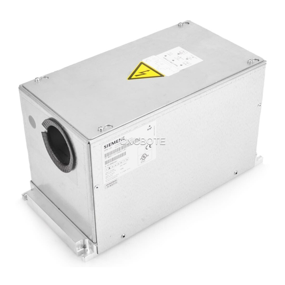
VPM 120
Spannungsbegrenzungsmodul
Betriebsanleitung
Best. Nr.: A5E00302281B
Anwendungsbereich
Das VPM wird bei permanentmagneterregten Synchron-
motoren mit hoher EMK eingesetzt, um die Zwischen-
kreisspannung am Umrichter im Fehlerfall durch
Kurzschluss der Motorklemmen zu begrenzen.
Maßbild (mm)
Bild 1
Siemens AG A&D SE WKC
6SN1113-1AA00-1JA1
C
150
6,4
9,5
125
C
A5E00302281B
Voltage Protection Module
Operating Instructions
Order No.: A5E00302281B
Field of application
The VPM is used for permanent-magnet synchronous
motors with high EMF to limit the DC link voltage at the
inverter when a fault occurs by short-circuiting the motor
terminals.
Dimension drawing (mm)
Fig. 1
180
180
20
20
4 x M5 screw mounting
cable and cable type
08 / 2009
1
2
3
4
5
X
Seite 1 von 13
Page 1 of 13
Advertisement
Table of Contents

Related Manuals for Siemens 6SN1113-1AA00-1JA1


Summarization of Contents
Product Overview and Application
Field of Application
Describes the VPM's use for permanent-magnet synchronous motors to limit DC link voltage during faults.
Dimension Drawing
Provides dimensional drawings and measurements for the VPM unit in millimeters.
Wiring Diagram and Connections
Wiring Diagram
Illustrates the electrical connections between the VPM, inverter, and motor.
Terminal Descriptions
Details the function of key terminals for pulse enable and voltage enabling.
Definitions, Safety Symbols, and Personnel
Qualified Personnel Requirements
Specifies the qualifications required for personnel handling the product and its installation.
Safety Symbol Definitions
Explains the meaning of safety symbols: DANGER, WARNING, CAUTION, and NOTICE.
Technical Notes and System Compatibility
Lists compatible systems and notes for using the VPM with other components.
General Safety and Installation Compliance
Electrical Hazards and Precautions
Highlights dangers from hazardous voltages and requirements for safe operation.
Installation Compliance Requirements
Stresses adherence to DIN/VDE regulations and national standards for installation.
Functionality and Principle of Operation
Functional Principle of VPM
Explains how the VPM limits motor terminal voltages during faults by short-circuiting.
Installation and Commissioning Procedures
Installation Safety Procedures
Details safety steps before installation, including switching off mains and securing.
Installation Guidelines
Covers wiring rules, component placement, clearances, and temperature limits.
Commissioning Process
Outlines the commissioning steps, which follow the converter system's instructions.
Troubleshooting and Functional Testing
Fault Finding and Remedies
Provides steps to troubleshoot issues with SIMODRIVE and SINAMICS systems.
Maintenance and Test Results
Test Results and Maintenance
Describes typical test results and routine maintenance tasks for the VPM.
Wiring Method and Environmental Conditions
Wiring Method Details
Specifies connection types for signalling contact X3 and power lines U, V, W, PE.
Installation Rules and Ambient Conditions
Covers installation regulations and environmental requirements for operation and storage.
Technical Data
Normal Operation Characteristics
Details VPM voltage type, DC link voltage, ramp-up time, response voltage, and frequency.
Short-circuit Operation Characteristics
Defines short-circuit operation and lists maximum permissible short-circuit times and currents.
Protection Function and Dimensions
Describes the signalling contact function and provides physical dimensions and weight.
Need help?
Do you have a question about the 6SN1113-1AA00-1JA1 and is the answer not in the manual?
Questions and answers