Table of Contents
Advertisement
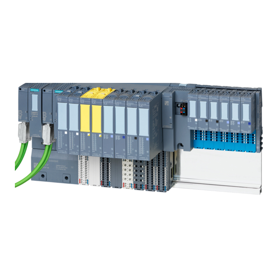
SIMATIC
ET 200SP HA
DI 16x24VDC HA
Equipment Manual
6DL1131-6BH00-0PH1
6DL1131-6BH00-0EH1
10/2020
A5E39265608-AD
Security information
Preface
2D Matrix code (QR code /
EAN code)
Product overview
Terminal
Parameters
Displays and interrupts
Technical specifications
Drivers, parameters,
diagnostics messages and
address space
1
2
3
4
5
6
7
8
A
Advertisement
Table of Contents

Related Manuals for Siemens 6DL1131-6BH00-0PH1


Summarization of Contents
Preface
Validity of the documentation
Details the I/O modules covered by the manual and complements system manuals.
2D Matrix code (QR code / EAN code)
Access to product-related information
Explains how to access product information via a mobile app and online resources.
Product overview
I/O module
Defines the DI 16x24VDC HA module and its key properties.
Accessories
Lists and describes accessories available for the I/O module.
Output disable switch
Explains the function and operation of the output disable switch.
Pulling the I/O module in runtime
Details the procedure for safely removing the I/O module while the system is running.
Terminal blocks
Describes available terminal blocks for connecting components to the I/O module.
Terminal
Pin assignment
Provides the general pin assignment for terminals when wiring a connector.
Sample connection schemes
Illustrates connection examples for 1-wire, 2-wire, and 3-wire configurations.
Schematic circuit diagram
Presents the block diagram for the I/O module's internal structure.
Parameters
Module/channel parameters
Specific parameters that affect the entire module or individual channels.
Parameter reassignment
Explains how configuration changes affect module reactions and other functions.
Explanation of module/channel parameters
Detailed descriptions of various module and channel configuration parameters.
Displays and interrupts
Status and error displays
Explains the LED indicators and their meaning for status and error reporting.
LEDs
Details the function and display of diagnostic (DIAG), maintenance (MT), and power (PWR) LEDs.
Channel status / fault LEDs
Describes how channel status and fault LEDs indicate input signal level and channel errors.
Interrupts
Lists events that trigger diagnostics or maintenance interrupts for the I/O module.
Technical specifications
General Information
Covers article number, firmware version, and usable terminal block types.
Supply voltage and input current
Specifies voltage ranges, reverse polarity protection, and input current consumption.
Digital inputs and characteristic curves
Details digital input properties, parameterization, and input characteristic curves.
Ambient conditions and dimensions
Outlines operating temperature ranges, isolation, dimensions, and weight of the module.
Drivers, parameters, diagnostics messages and address space
Parameter assignment
Explains how to reconfigure module channels in RUN using the WRREC instruction.
Structure of data record 128
Details the byte structure of data record 128 used for parameter transfer.
Diagnostics messages
Lists diagnostic messages, their causes, meanings, and recommended remedies.
Maintenance events
Describes maintenance events, their causes, and the required actions for resolution.
Hardware interrupts
Explains how hardware interrupts are generated for rising/falling edges and how they are recorded.
Address space
Maps the I/O module's address space for digital inputs and time stamping.
Need help?
Do you have a question about the 6DL1131-6BH00-0PH1 and is the answer not in the manual?
Questions and answers