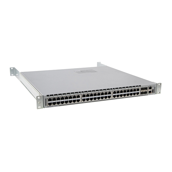
Summarization of Contents
Chapter 1 Overview
Installation Process
Describes the sequence of tasks for switch installation, including site prep and tool assembly.
Safety Information
Provides essential safety guidelines and warnings for handling and installing the equipment.
Obtaining Technical Assistance
Details the methods to contact Arista Networks for support, including email, web, and phone.
Chapter 2 Preparation
Site Selection
Outlines criteria for choosing an appropriate installation site, considering temperature, ventilation, and rack space.
Tools and Parts Required for Installation
Lists the necessary tools and components for mounting the switch in a rack.
Electrostatic Discharge (ESD) Precautions
Details measures to prevent damage to the switch from static electricity during installation.
Chapter 3 Rack Mounting the Switch
Two-Post Rack Mount
Explains the procedure for mounting the switch using brackets in a two-post rack system.
Four-Post Rack Mount
Describes the process of mounting the switch using rails and brackets in a four-post rack system.
Chapter 4 Cabling the Switch
Grounding the Switch
Covers procedures for connecting the switch to the data center ground for safety.
Connecting Power Cables
Details how to connect AC and DC power cables to the switch for operation.
Connecting Serial and Management Cables
Explains how to connect console, USB, and Ethernet management ports for access and configuration.
Chapter 5 Configuring the Switch
Manual Configuration Procedure
Outlines the steps to manually configure the switch, including setting passwords and IP addresses.
Appendix A Status Indicators
Front Indicators
Describes the status LEDs on the front panel of the switch for system, fan, and power supply monitoring.
Rear Status Indicators
Explains the status LEDs on the fan and power supply modules located on the rear of the switch.
Appendix B Parts List
Rack Mount Parts
Lists the components included in the accessory kit for mounting the switch in an equipment rack.
Appendix C Front Panel
Port-Speed Groups
Explains port grouping features for flexible Ethernet speed configuration on specific switch models.
Front Panels
Displays diagrams of the front panels of various Arista switches, identifying ports and indicators.


Need help?
Do you have a question about the DCS-7280CR3-96 and is the answer not in the manual?
Questions and answers