
Related Manuals for Arista CCS-722XPM-48Y4


Summarization of Contents
Chapter 1: Overview
1.1 Scope
This guide covers Arista Networks Cognitive Campus Switches. It is intended for trained service personnel and technicians.
1.2 Receiving and Inspecting the Equipment
Inspect shipping boxes for damage upon receipt. Retain packing materials if damage is suspected for carrier inspection.
1.3 Installation Process
Outlines the essential steps for switch installation: site selection, tool assembly, rack mounting, cabling, and configuration.
1.4 Safety Information
Directs users to the Arista Networks Safety Information document for critical safety warnings and guidelines.
1.5 Obtaining Technical Assistance
Details methods for obtaining technical support, including email, web portal, and phone contact information.
1.6 Specifications
Provides technical specifications including dimensions, weights, operating conditions, and power supply details.
Chapter 2: Preparation
2.1 Site Selection
Criteria for selecting an installation site, focusing on temperature, ventilation, and airflow orientation for optimal operation.
2.2 Tools and Parts Required for Installation
Lists required tools and parts for installation, including those provided in the accessory kit and additional items.
2.3 Electrostatic Discharge (ESD) Precautions
Guidelines to prevent ESD damage during installation and servicing, emphasizing static-free work environments and equipment handling.
Chapter 3: Rack Mounting the Switch
3.1 Two-Post or Four-Post Rack Mount
Instructions for mounting the switch in either a two-post or four-post rack, noting the identical installation process.
3.1.1 Attaching Mounting Brackets to the Chassis
Procedure for attaching the mounting brackets to the switch chassis using provided screws.
3.1.2 Inserting the Switch into the Rack
Steps for physically installing the switch into an equipment rack, securing it to the rack posts.
Chapter 4: Cabling the Switch
4.1 Grounding the Switch
Procedure for connecting the switch to the data center ground after rack mounting for electrical safety.
4.2 Connecting Power Cables
Information on connecting power cords, noting they are optional, must be ordered separately, and require approved cords.
4.2.1 AC Power Supplies
Details supported AC power supplies, their models, and connection requirements for the switch.
4.2.2 DC Power Supplies
Details supported DC power supplies, their models, and connection requirements for the switch.
4.2.2.1 Wire and Lug Preparation
Steps for preparing DC power wiring, including ensuring power removal and using appropriate lugs and torque.
4.2.2.2 Connecting a DC Power Supply to Power Source
Procedure for connecting DC power input wires to the switch terminals in the specified order.
4.3 Connecting Serial and Management Cables
Instructions for connecting console and Ethernet management cables for switch configuration and monitoring.
Appendix A: Status Indicators
A.1 Front Indicators
Overview of status indicators on the front panel, including system, fan, and power supply LEDs.
A.1.1 Switch Indicators
Details front panel LEDs for system, fan, and power supply status, including their states and meanings.
A.1.2 Port Indicators
Describes port LEDs indicating link and operational status for network ports on the switch.
A.2 Rear Status Indicators
Information on status LEDs for fan modules and power supplies located on the rear panel of the switch.
Appendix B: Part List
B.1 Rack Mount Parts
Lists components included in the accessory kit for rack mounting, such as brackets and screws.
B.2 Cables
Lists cables provided in the accessory kit for installation and optional power cables.
Appendix C: Front Panel
CCS-720XP-48ZC2 Front Panel
Illustrates the front panel of the CCS-720XP-48ZC2 switch, detailing ports and status indicators.
CCS-720XP-24ZY4 Front Panel
Illustrates the front panel of the CCS-720XP-24ZY4 switch, detailing ports and status indicators.
CCS-720XP-48Y6 Front Panel
Illustrates the front panel of the CCS-720XP-48Y6 switch, detailing ports and status indicators.
CCS-720XP-24Y6 Front Panel
Illustrates the front panel of the CCS-720XP-24Y6 switch, detailing ports and status indicators.
CCS-722XPM-48ZY8 Front Panel
Illustrates the front panel of the CCS-722XPM-48ZY8 switch, detailing ports and status indicators.
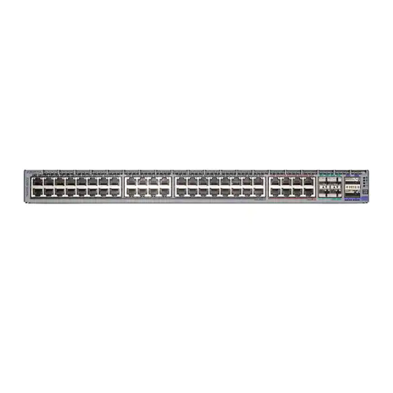
CCS-722XPM-48Y4 Front Panel
Illustrates the front panel of the CCS-722XPM-48Y4 switch, detailing ports and status indicators.
Appendix D: Rear Panel
Rear Panel for CCS-720XP-48ZC2
Illustrates the rear panel of the CCS-720XP-48ZC2 switch, detailing ports, power supplies, and fan modules.
Appendix E: Maintenance and Field Replacement
E.1 Considerations
Key considerations for maintenance and field replacement, including hot-swappable components and slot filling.
E.2 Power Supplies
Details procedures for removing and installing AC and DC power supplies, including safety steps.
E.2.1 AC Power Supplies
Step-by-step guide for removing an existing AC power supply and installing a new one.
E.2.2 DC Power Supplies
Step-by-step guide for removing and installing DC power supplies, including wiring and torque specifications.
E.3 Fan Modules
Procedure for hot-swapping fan modules, emphasizing timely replacement to prevent overheating.
E.3.1 Removing a Fan Module
Steps for safely removing a fan module from the switch, including grounding and using the release lever.
E.3.2 Installing a Fan Module
Steps for installing a new fan module into the switch, ensuring it is properly seated and verified.
Need help?
Do you have a question about the CCS-722XPM-48Y4 and is the answer not in the manual?
Questions and answers