
Subscribe to Our Youtube Channel
Related Manuals for Arista CCS-710P-12


Summary of Contents for Arista CCS-710P-12
- Page 1 Quick Start Guide Ethernet Switch CCS-710P-12 CCS-710P-16P Arista Networks www.arista.com DOC-05297-01...
- Page 2 The trademarks, logos and service marks ("Marks") displayed in this documentation are the property of Arista Networks in the United States and other countries. Use of the Marks are subject to Arista Network’s Term of Use Policy, available at www.arista.com/en/terms-of-use. Use of marks belonging to other parties is for informational purposes only.
-
Page 3: Table Of Contents
4.6.2 Inserting the Switch into the Rack................19 Chapter 5: Grounding the Switch............21 Chapter 6: Status Indicators..............23 Chapter 7: Parts List................27 Chapter 8: Front Panel................29 8.1 CCS-710P-12 Front Panel....................29 8.2 CCS-710P-16P Front Panel....................30 8.3 Operating Mode Button......................31... - Page 4 Chapter 9: Rear Panel................33 Chapter 10: Regulatory Model Numbers..........35 Appendix A: Screw Size Details............37 Appendix B: Class A EMC Statement..........39 Appendix C: China RoHS..............41 Appendix D: BSMI RoHS..............43...
-
Page 5: Chapter 1: Overview
Chapter 1 Overview This Quick Start Guide (QSG) describes the Arista Ethernet Switch of CCS-710P Series. This chapter contains the following topics: • Scope • Intended Audience • Receiving and Inspecting the Equipment • Installation Process • Safety Information •... -
Page 6: Safety Information
4. Connect the switch to the power source and network devices. 5. Configure the switch. Safety Information Refer to the Arista Networks document Safety Information and Translated Safety Warnings available at https://www.arista.com/en/support/product-documentation Obtaining Technical Assistance Any customer, partner, reseller or distributor holding a valid Arista Service Contract can obtain technical support in any of the following ways: •... -
Page 7: Chapter 2: Specifications
Chapter 2 Specifications This section lists the specifications of Arista Ethernet Switch (includes CCS-710P-12 and CCS-710P-16P). Table 1: Switch Specifications (Dimensions and Weights) Switch Size (L x W x H) Weight CCS-710P-12 (AN1758) 213.36 x 269 x 43.5 mm 2.05 kg (4.51 lbs) (8.4 x 10.59 x 1.7 inches) - Page 8 Table 4: Switch Specifications (PoE Power Budget) Switch PSU Model PoE Power Budget CCS-710P-12 (AN1758) PWR-150-ADP 110W CCS-710P-12 (AN1758) PWR-280-ADP 240W CCS-710P-16P (AN1786) 90W PoE PD CCS-710P-16P (AN1786) PWR-150-ADP 100W CCS-710P-16P (AN1786) PWR-280-ADP 230W...
-
Page 9: Chapter 3: Preparation
Chapter 3 Preparation This section describes the initial setup and preparation for installing the switch. This chapters contains the following topics: • Site Selection • Tools and Parts Required for Installation • Electrostatic Discharge (ESD) Precautions Site Selection The following criteria should be considered when selecting a site to install the switch: •... -
Page 10: Electrostatic Discharge (Esd) Precautions
Electrostatic Discharge (ESD) Precautions Observe these guidelines to avoid ESD damage when installing or servicing the switch. • Assemble or disassemble equipment only in a static-free work area. • Use a conductive work surface (such as an anti-static mat) to dissipate static charge. •... -
Page 11: Chapter 4: Mounting The Switch
Chapter 4 Mounting the Switch This section describes different types of mounting the switch. The chapter contains the following topics: • Wall Mount • L-Bracket Wall Mount (Default) • 3-in-1 Bracket Wall Mount (Optional) • Under Table Mount • L-Bracket Under Table Mount (Default) •... -
Page 12: 3-In-1 Bracket Wall Mount (Optional)
Screw M4x25mm Flat head screw M4x6mm Screw anchor M4 Flat surface wall Note: For more information regarding the screw size, refer to #unique_27/ unique_27_Connect_42_section_b1r_xt1_yqb 1. Position the L-Bracket aligning with the chassis holes on the side of the switch and fix it with M4x6mm flat head screws. - Page 13 Mounting the Switch Flat surface wall Figure 3: Wall Mounting the Switch Chassis Cross hole 3-in-1 bracket Flat head screw M4x6mm Flat surface wall Flat head screw M4x6mm Note: For more information regarding the screw size, refer to #unique_27/ unique_27_Connect_42_section_b1r_xt1_yqb 1.
- Page 14 Cross hole stud Aligning stud to the cross hole 6. Tighten the screws to mount the device firmly to the wall and connect to the power supply. 7. Place the PSU adapter bracket on the PSU and fix with cable ties around it. PSU adapter bracket Cable ties 8.
-
Page 15: Under Table Mount
Mounting the Switch Under Table Mount This section provides instructions for mounting the switch under the table/desk. 4.2.1 L-Bracket Under Table Mount (Default) This section provides instructions for mounting the switch under the table/desk using L-Bracket. Figure 4: Under Table Mounting the Switch using L-Bracket Flat wooden table L-Bracket Flat head screw M4x6mm... -
Page 16: 3-In-1 Bracket Under Table Mount (Optional)
4.2.2 3-in-1 Bracket Under Table Mount (Optional) This section provides instructions for mounting the switch under the table/desk using 3-in-1 mounting bracket. Figure 5: Attaching 3-in-1 Bracket under the Table Flat wooden table Screw hole Screw anchor M4 3-in-1 bracket Screw M4x25mm... - Page 17 Mounting the Switch Switch Figure 6: Under Table Mounting the Switch Flat wooden table Cross hole 3-in-1 bracket Flat head screw M4x6mm Note: For more information regarding the screw size, refer to #unique_27/ unique_27_Connect_42_section_b1r_xt1_yqb Note: Ensure that the flat wooden table surface has a minimum thickness of 25mm for under table mounting.
-
Page 18: Desktop Mount (Default)
Desktop Mount (Default) This section provides instructions for mounting the switch on the desktop or any flat surface. Figure 7: Attaching Rubber Feet to Bottom of Switch Rubber feet Note: Make sure that the device is not stacked and avoid placing anything on the top cover of the device. -
Page 19: Magnetic Mount (Optional)
Mounting the Switch Magnetic Mount (Optional) This section provides instructions for magnetic mounting the switch. Magnetic mounting is applicable to mount only on metal surfaces. Figure 8: Magnetic mount Rubber Magnet 3-in-1 bracket Switch facing downwards Cross hole Flat head screw M4x6mm Note: For more information regarding the screw size, refer to #unique_27/ unique_27_Connect_42_section_b1r_xt1_yqb... -
Page 20: Din Rail Mount (Optional)
DIN Rail Mount (Optional) This section provides instructions for mounting the switch using DIN rail. Figure 9: DIN Rail Mounting Chassis DIN mount bracket DIN rail hook Flat head screw M4x6mm DIN rail Note: For more information regarding the screw size, refer to #unique_27/ unique_27_Connect_42_section_b1r_xt1_yqb 1. - Page 21 Mounting the Switch 3. Attach the DIN rail to the mounting bracket with the help of DIN rail hook as shown in the below image. DIN mount bracket DIN rail hook DIN rail holder 4. Press the DIN rail holder firmly and rotate the chassis to fit in the device. 5.
-
Page 22: 1Ru Rack Mount (Optional)
6. Position the PSU adapter bracket on the DIN mount bracket by aligning with the screw holes and fix it with M4x8mm thread screws. The PSU is attached to the DIN rail. DIN rail DIN mount bracket Thread screw M4x8mm Cable ties PSU rubber pads 1RU Rack Mount (Optional) -
Page 23: Inserting The Switch Into The Rack
Mounting the Switch Rack Switch Note: Ensure that there is about 1U rack spacing between the two devices on the rack. 1. Align the rack mounting brackets with the chassis holes at the front of the switch. 2. Secure the mounting brackets using the screws provided in the rack mounting kit. 4.6.2 Inserting the Switch into the Rack This section describes the steps to attach the switch into the rack. - Page 24 Power adapter 4. Connect the power adapter to the switch as shown in the below image. Cable ring Cable ties 5. Position the rack against the rack posts and mount the rack to the equipment rack. Screw M4x8mm Rack posts 6.
-
Page 25: Chapter 5: Grounding The Switch
Chapter 5 Grounding the Switch This section provides instructions for grounding the switch. Normally, the functional grounding of the switch is achieved through the DC input connection. If you would like to do additional grounding, follow the instructions below: Figure 12: Grounding the Switch Screw M4 (with washer) Solder terminal lug (loop ring lug) Grounding point... -
Page 27: Chapter 6: Status Indicators
Chapter 6 Status Indicators This section describes the front panel LED status of the device. Figure 13: LED Status Indicators Table 5: Switch LED States LED Name LED State Device Status System Status LED No power or in the midst of a power cycle. - Page 28 LED Name LED State Device Status Power Supply Status LED Power supply adapter is not available. Green Power supply adapter is fully functional. Amber Power supply adapter has a fault. PD Port Power Status LED PD port power is not available. (710P-16P only) Green PD port power is fully functional.
- Page 29 Status Indicators Port LEDs Normal Mode PoE Mode Speed Mode 5GE RJ45 Port Port link is No PoE Blinking Amber 1G down (P15, 710P-16P Green Port link is up Amber 2.5G only) Amber Port is software Green disabled 5GE RJ45 Port Port link is No PoE Blinking Amber 1G...
-
Page 31: Chapter 7: Parts List
Arista Power Adapter, 280W, PoE, AC (Spare) KIT-CCS-710 Accessory Kit for Arista 710P Series switches KIT-CCS-710-DIN DIN-Rail Mount Kit for Arista 710P Series switches KIT-CCS-710-RM Rack Mount Kit for Arista 710P Series switches KIT-CCS-710-MGN Magnet Mount Kit for Arista 710P Series switches... -
Page 33: Chapter 8: Front Panel
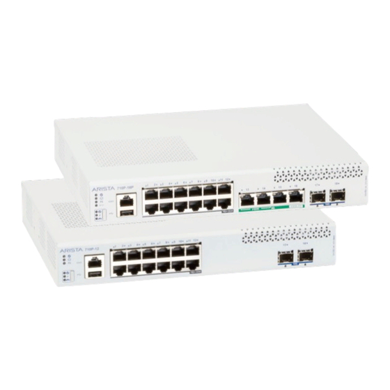
Chapter 8 Front Panel This section describes the front panel of the Ethernet Switch (CCS-710P-12 and CCS-710P-16P). This chapter contains the following topics: • CCS-710P-12 Front Panel • CCS-710P-16P Front Panel • Operating Mode Button CCS-710P-12 Front Panel The CCS-710P-12 front panel includes the following key components:... -
Page 34: Ccs-710P-16P Front Panel
CCS-710P-16P Front Panel The CCS-710P-16P front panel includes the following key components: Figure 15: CCS-710P-16P Front View System status LEDs 1GE RJ45 port LEDs 5GE port LEDs SFP+ ports SFP+ port LEDs 6A: Uplink 5 Gigabit Ethernet RJ45 port with 90W PD 6B: Uplink 5 Gigabit Ethernet RJ45 port 6C: 5 Gigabit Ethernet RJ45 ports with 60W PSE Gigabit Ethernet RJ45 ports with 30W PSE... -
Page 35: Operating Mode Button
Front Panel Operating Mode Button This section describes the functionality of the mode button located on the front panel of the switch. Figure 16: Mode Button States The mode button port LEDs will transition to different modes as listed below when the user presses the mode button for less than 2 seconds and the same is indicated by the corresponding mode status LED. -
Page 37: Chapter 9: Rear Panel
Chapter 9 Rear Panel The section describes the rear panel of the Ethernet Switch (CCS-710P-12 and CCS-710P-16P). The rear panel includes the following key components: Figure 17: CCS-710P-12 and CCS-710P-16P Rear View Earth grounding point Kensington lock hole Power supply... -
Page 39: Chapter 10: Regulatory Model Numbers
Chapter 10 Regulatory Model Numbers This section lists the regulatory model numbers (RMNs) of the ethernet switch described in this document. Table 8: Regulatory Model Numbers and Product Numbers Regulatory Model Number (RMN) Product Number AN1758 CCS-710P-12 AN1786 CCS-710P-16P... -
Page 41: Appendix A: Screw Size Details
Appendix A Screw Size Details Refer to the following template for detailed screw size information. -
Page 43: Appendix B: Class A Emc Statement
Appendix B Class A EMC Statement Refer to the following section for detailed Class A EMC Statement. Figure 18: Traditional Chinese Class A EMC Statement (Taiwan) -
Page 45: Appendix C: China Rohs
Appendix C China RoHS This appendix provides RoHS information for ethernet switch covered by this guide. Figure 19: China RoHS... -
Page 47: Appendix D: Bsmi Rohs
Appendix D BSMI RoHS This appendix provides RoHS information for ethernet switch covered by this guide. Figure 20: BSMI RoHS...
Need help?
Do you have a question about the CCS-710P-12 and is the answer not in the manual?
Questions and answers