Arista CCS-720XP Series Quick Start Manual

Arista CCS-720XP Series Quick Start Manual

Cognitive campus switches

Advertisement

Quick Start Guide
CCS-720XP and CCS-722XPM
Series 1 RU (Gen 3)
Cognitive Campus
Switches
Arista Networks
www.arista.com
DOC-00158-05

Advertisement

Table of Contents
loading
Need help?

Need help?

Do you have a question about the CCS-720XP Series and is the answer not in the manual?

Questions and answers

Subscribe to Our Youtube Channel

Summary of Contents for Arista CCS-720XP Series

  • Page 1 Quick Start Guide CCS-720XP and CCS-722XPM Series 1 RU (Gen 3) Cognitive Campus Switches Arista Networks www.arista.com DOC-00158-05...
  • Page 2 The trademarks, logos and service marks ("Marks") displayed in this documentation are the property of Arista Networks in the United States and other countries. Use of the Marks are subject to Arista Network Term of Use Policy, available at http://www.arista.com/en/terms-of-use. Use of marks belonging to other parties is for...
  • Page 3: Table Of Contents

    Contents Contents Chapter 1: Overview................1 1.1 Scope............................1 1.2 Receiving and Inspecting the Equipment................1 1.3 Installation Process.........................1 1.4 Safety Information........................2 1.5 Obtaining Technical Assistance..................... 2 1.6 Specifications.......................... 3 Chapter 2: Preparation................5 2.1 Site Selection..........................5 2.2 Tools and Parts Required for Installation................6 2.3 Electrostatic Discharge (ESD) Precautions................
  • Page 4 E.3 Fan Modules.........................32 Appendix F: Regulatory Model Numbers..........35 Appendix G: Taiwan RoHS Information..........37...
  • Page 5: Chapter 1: Overview

    • Safety Information • Obtaining Technical Assistance • Specifications Scope This guide is intended for properly trained service personnel and technicians who need to install the following Arista Networks Cognitive Campus Switches: CCS-720XP-48ZC2 CCS-720XP-24ZY4 CCS-720XP-48Y6 CCS-720XP-24Y6 CCS-722XPM-48ZY8 CCS-722XPM-48Y4 Note: Only qualified personnel should install, service, or replace this equipment.
  • Page 6: Safety Information

    Refer to the Arista Networks document Safety Information and Translated Safety Warnings available at: https://www.arista.com/en/support/product-documentation. Obtaining Technical Assistance Any customer, partner, reseller or distributor holding a valid Arista Service Contract can obtain technical support in any of the following ways: •...
  • Page 7: Specifications

    Some switches could use power supplies that may no longer be available or other PSUs besides the default shown. Contact your local Arista representative for more information. For switches that support both forward and reverse airflows, add -RED or -BLUE to the PSU...
  • Page 8 Table 5: Switch Specifications (Power Draw) Switch Power Draw Supported Power PoE Power Budget (Typical /Maximum) Supply Single / Dual PSU CCS-720XP-48ZC2 141 W / 156 W PWR-1021-AC-RED 909 W / 1787 W CCS-720XP-24ZY4 141 W / 156 W PWR-621-AC-RED 509 W / 1787 W CCS-720XP-48Y6 68 W / 93 W...
  • Page 9: Chapter 2: Preparation

    The fans and PSUs determine the airflow direction through the switch. The color of the visible handles or labels indicate the airflow direction. Note: The figures shown use representative Arista switches to illustrate airflow directions. Refer to rear panel to determine the airflow for your switch.
  • Page 10: Tools And Parts Required For Installation

    Figure 2: Air Exit Module Orient the switch such that the airflow through the switch is from the cooler to the hotter aisle. If the airflow direction is not compatible with the installation site, contact your sales representative. • Rack Space: Install the switch in a 19" rack or cabinet. The switch height is 1 RU. The accessory kit provides mounting brackets for two-post and four-post racks.
  • Page 11: Electrostatic Discharge (Esd) Precautions

    Preparation Four-Post Rack (Tool-less) No additional equipment required. Four-Post Rack (Conventional) • Screws or rack mounting nuts and bolts. • Screwdriver Accessory kit does not include screws for attaching the switch to the equipment rack. When installing the switch into an equipment rack with unthreaded post holes, nuts are also required to secure the switch to the rack posts.
  • Page 13: Chapter 3: Rack Mounting The Switch

    After completing the instructions for your rack type, proceed to Cabling the Switch. Note: Illustrations use a representative Arista switch. Your device may be different in appearance. Two-Post or Four-Post Rack Mount The switch can be installed in a two-post or four-post rack. The installation process is identical because the switch attaches to only two posts of a rack.
  • Page 14 Figure 4: Bracket Mount Attachment to Switch 3.1.2 Inserting the Switch into the Rack This procedure attaches the switch to the rack. 1. Lift the chassis into the rack. Position the flanges against the rack posts. 2. Select mounting screws that fit your equipment rack. 3.
  • Page 15: Chapter 4: Cabling The Switch

    8 Power supply 1 12 Ground Connecting Power Cables Power cords are optional and must be ordered separately. You must use an approved power cord compliant with local and national electrical codes or order one from Arista for use with the device.
  • Page 16 Note: Installation of this equipment must comply with local and national electrical codes. If necessary, consult with the appropriate regulatory agencies and inspection authorities to ensure compliance. Installation de cet équipement doit être conformes aux codes électriques locaux et nationaux. Si nécessaire, consulter les organismes de réglementation appropriés et des autorités de contrôle pour assurer la conformité.
  • Page 17 Cabling the Switch 3 Handle The power supplies have a C16 connector and require power cables that comply with IEC-320. 4.2.2 DC Power Supplies The following DC power supplies are supported. PWR-721-DC-RED Figure 8: DC Power Supply (PWR-721-DC-RED) displays a DC power supply. Figure 8: DC Power Supply (PWR-721-DC-RED) 1 Power supply status LED 4 Battery return (RTN)
  • Page 18 Note: Stranded copper wiring is required and should meet local and national installation requirements. Wires and grounding lugs are not supplied. 1. Attach an ESD grounding strap. 2. Prepare the stranded copper wiring for the power supply to be used. Table 6: Wiring, Lug, and Tightening Torques for DC PSU provides wiring, lug, and tightening torque information for the...
  • Page 19: Connecting Serial And Management Cables

    Cabling the Switch b. Negative source DC cable to the negative (- / -48V) terminal. Positive (+) source DC cable to the positive (+ / Rtn) terminal. Note: Ensure power is removed from DC circuits before performing any installation actions. Locate circuit breakers or fuses on DC power lines servicing the circuits.
  • Page 20 Figure 10: Rear Panel Management Ports 1 Speed status LED 4 USB port 2 Activity status LED 5 Serial console port 3 Ethernet management port Connect management ports as follows: • Console (Serial) Port: Connect to a PC with the RJ-45 to DB-9 serial adapter cable. The switch uses the following default settings: •...
  • Page 21: Chapter 5: Configuring The Switch

    Chapter 5 Configuring the Switch Arista switches ship from the factory in Zero Touch Provisioning (ZTP) mode. ZTP configures the switch without user intervention by downloading a startup configuration file or a boot script from a location specified by a DHCP server. To manually configure a switch, ZTP is bypassed. The initial configuration provides one username (admin) accessible only through the console port because it has no password.
  • Page 22 11. When the management port IP address is configured, use this command to access the switch from a host, using the address configured in Step 9: ssh admin@192.0.2.8 Refer to the Arista Networks User Manual for complete switch configuration information.
  • Page 23: Appendix A: Status Indicators

    Appendix A Status Indicators The Status Indicators section reviews the following topics: • Front Indicators • Rear Status Indicators Front Indicators Reviews the Switch and Port indicators of the device. A.1.1 Switch Indicators Front panel LEDs are located on the right side of the chassis and display system, fan, and power supply status.
  • Page 24 LED Name LED State Device Status Amber Two or more fans (any combination of fan modules or PSU fans) are disconnected or malfunctioning. The switch will automatically execute a âgraceful shutdownâ shortly. Fan Status LED Green All fan and power modules are operating normally. Amber Single fan module is removed or malfunctioning.
  • Page 25: Rear Status Indicators

    Status Indicators LED State Status Yellow Port is software disabled. Flashing Yellow Port failed diagnostics. Rear Status Indicators Fan and power supply modules are accessed from the rear panel. Each fan and power supply module contains an LED that reports the module status. Fan Status LEDs are on the fan modules, as displayed in Figure 13: Fan Status LED.
  • Page 26 Note: You can narrow down the error condition by logging in to the switch to view the specific device state. Refer to the Arista User Manual's Switch Environment Control chapter, under the topic Viewing Environment Status, for further information on the show environment...
  • Page 27: Appendix B: Part List

    Lists the cables required for installation of the device. Quantity Description RJ-45 Patch Panel Cable RJ-45 to DB9 Adapter Cable Optional (must be ordered separately) Power cables: IEC-320/C13- C14, 13 A, 250 V Note: All provided power cables are for use only with Arista products.
  • Page 29: 
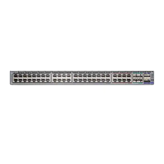
Appendix C: Front Panel

    Appendix C Front Panel This appendix displays the front panel of all switches covered by this guide. Figure 16: CCS-720XP-48ZC2 1 25G SFP ports 5 Power supply 2 status 2 System status LED 6 100G QSFP ports 3 Fan status LED 7 5G PoE+ ports 4 Power supply 1 status 8 2.5G PoE+ ports...
  • Page 30 4 Power supply 1 status Note: The 2.5G ports are PoE+ (30 W max) and the 5G ports are PoE+ (60 W max). Figure 18: CCS-720XP-48Y6 1 25G SFP ports 5 Power supply 2 status 2 System status LED 6 1G PoE+ ports 3 Fan status LED 4 Power supply 1 status Note: The 1G ports are PoE+ (30 W max).
  • Page 31 Front Panel Figure 20: CCS-722XPM-48ZY8 1 System status LED 5 25G SFP ports 2 Fan status LED 6 2.5G PoE+ ports 3 Power supply 1 status 4 Power supply 2 status Note: The 2.5G ports are PoE+ (60 W max). Figure 21: CCS-722XPM-48Y4 1 System status LED 5 10G SFP ports...
  • Page 33: Appendix D: Rear Panel

    Appendix D Rear Panel All switches covered by this guide use one of the rear panels shown below. Note: Depending on the installed power supply and fan modules, the appearance could be different from those shown. Figure 22: Rear Panel for CCS-720XP-48ZC2 (Representative switch) 1 Ground 6 Fan module 2 handle 11 Power supply 1...
  • Page 35: Appendix E: Maintenance And Field Replacement

    All slots must be filled or covered with a blank for operation (even though power supply or fans may not be functional). • Before you begin, refer to the Arista Networks document Safety Information and Translated Safety Warnings available at: https://www.arista.com/en/support/product-documentation. Note: Refer to the front...
  • Page 36: Dc Power Supplies

    5. Verify the LED(s) on the power supply. Note: The Power Supply status LED is a steady green for normal operation. 6. Verify the new power supply operation by issuing the show environment power command. switch#show environment power The output of the command lists the power supplies in operation and includes the one you replaced. E.2.2 DC Power Supplies Note: Use a three-eighth inch (3/8") hexagon-socket wrench for removing the lug nuts.
  • Page 37 Maintenance and Field Replacement 1. Ground yourself with an ESD wrist strap. 2. Push the fan module release lever and slide the fan module out of the switch. E.3.2 Installing a Fan Module You must make space for installing the fan module by removing an existing one Removing a Fan Module 1.
  • Page 39 Appendix F Regulatory Model Numbers This appendix lists the Regulatory Model Numbers (RMNs), where applicable, for the product models for the switches described in this document. Table 12: Regulatory Model Numbers and Product Numbers Regulatory Model Number Product Number(s) (RMN) AN1712 CCS-720XP-48ZC2 AN1714...
  • Page 41 Appendix G Taiwan RoHS Information This appendix provides Taiwan RoHS information for switches covered by this guide. For Taiwan BSMI RoHS Table, go to https://www.arista.com/assets/data/pdf/AristaBSMIRoHS.pdf.

Table of Contents