
Related Manuals for Russound CAM66X


Summary of Contents for Russound CAM66X
- Page 1 CAM6.6X-S1/S2 System 6-Zone, 6-Source XM Receiver and UNO Smart Keypads INSTRUCTION MANUAL...
-
Page 2: Important Safeguards
It is not necessary to make any other 17.Servicing - The user should not attempt to service the appliance beyond changes. If you have any questions please call Russound Inc. at that described in the operating instructions. All other servicing should 1-800-638-8055 or 603-659-5170 be referred to qualified service personnel. -
Page 3: Table Of Contents
TABLE OF CONTENTS USER SECTION Product Introduction ......................6 Component Guide CAM6.6 Controller.......................7 UNO-S1 Keypad ........................8 UNO-S2 Keypad .........................9 SRC2 Remote Control......................10 UNO-S1 Keypad Operation ....................11 UNO-S1 User Menu ......................12 UNO-S2 Keypad Operation ....................13 UNO-S2 User Menu ......................14 Internal Source - XM Tuner XM Radio Activation......................15 XM Radio Display ......................15 XM Radio Modes ......................16-19... - Page 4 TABLE OF CONTENTS Making Connections UNO Keypad Port Connections...................36 Source Audio Input Connections ..................37 Source IR Input Connections ....................37 Common IR Input Connection .....................38 Speaker Connections ......................39 Zone Fixed/Variable Audio Output ..................40 12VDC Home Theater Trigger In/Out ..................41 12VDC Mute Trigger In/Out....................42 RNET Link In/Out.......................43 RS-232 Interface .......................44 Optional Internal Source...
-
Page 5: User Section
USER SECTION Component Guides Explains front panel features of the CAM6.6 controller, UNO-S1 keypad, UNO-S2 keypad and SRC2 remote control. Operation Step-by-step outline of the system's normal operation, plus a look at adjustable features available through the User Menu. -
Page 6: Product Introduction
Master. If the party moves to the sunroom and porch, that room’s keypad can be set to Master instead. Here at Russound we are proud to continue providing innovative and intuitive audio product solutions to the world. When you link the industry-leading CAM6.6X-S1/S2 system with Russound’s commitment... -
Page 7: Component Guide Cam6.6 Controller
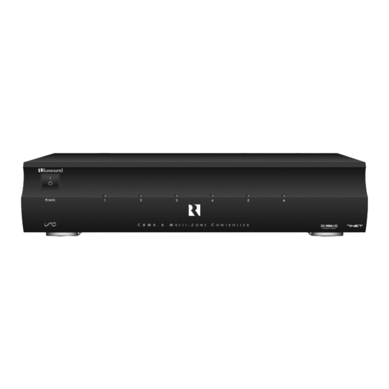
USER COMPONENT GUIDE CAM6.6 Controller-Front Panel MAIN POWER SWITCH - Supplies power to the CAM6.6 ROOM LED ON/OFF INDICATORS - Indicates when a room is on (green) or off (red) Main Power and Zone Status The power switch for the CAM6.6 controller is "on" in the up position. Any active room is indicated on the front of the controller by a green LED, which shows red when the room is inactive. -
Page 8: Uno-S1 Keypad
USER COMPONENT GUIDE UNO-S1 Keypad-Front Panel Blues LCD PANEL - 5-character backlit display shows status of the room, source, volume, and more SOURCE SELECT BUTTON - Scrolls through the sources directly connected to the CAM6.6. Press and hold brings up the USER MENU for loudness, bass, treble, etc. VOLUME UP/DOWN BUTTONS - Raises and lowers the volume for the room IR RECEIVER - Receives IR signals and passes them to the controller and source equip- ment. -
Page 9: Uno-S2 Keypad
USER COMPONENT GUIDE UNO-S2 Keypad-Front Panel CD PLAYER 1 LCD PANEL - 12-character backlit display shows status of the room, source, volume, and more SOURCE SELECT BUTTON - Scrolls through the sources directly connected to the CAM6.6. Press and hold brings up the USER MENU for loudness, bass, treble, etc. VOLUME UP/DOWN BUTTONS - Raises and lowers the volume for the room IR RECEIVER - Receives IR signals and passes them to the controller and source equip- ment. -
Page 10: Src2 Remote Control
(e.g., VCR, DVD, or CD player) with these buttons. SOURCE - Directly select sources connected to the Russound controller while in the Russound mode. F1 AND F2 BUTTONS - Selects and saves Favorite 1 or Favorite 2 preset selections. -
Page 11: Uno-S1 Keypad Operation
USER OPERATION UNO-S1 Keypad Zone On/Off Press and release to turn on the UNO User Menu with a press and hold action. (See System Keypad. This also turns on the corre- next page for User Menu) sponding CAM6.6’s room, and any presets previ- Volume Up/Down Buttons ously assigned will be activated, including set- The room’s audio output is adjusted using... -
Page 12: Uno-S1 User Menu
USER USER MENU SETTINGS UNO-S1 User Menu Operation The User Menu allows the user to adjust the When another UNO Systems Keypad selects the audio properties and control functions of a par- same source, a DND message will scroll on the ticular room. -
Page 13: Uno-S2 Keypad Operation
USER OPERATION UNO-S2 Keypad Zone On/Off Press and release to turn on the UNO is also used to enter the User Menu with a System Keypad. This also turns on the corre- press and hold action. (See next page for User sponding CAM6.6’s room, and any presets previ- Menu) ously assigned will be activated, including set-... -
Page 14: Uno-S2 User Menu
USER USER MENU SETTINGS UNO-S2 User Menu Operation The User Menu allows the user to adjust the 7. DO NOT DSTRB - On or Off (default) audio properties and control functions of a par- Do Not Disturb means do not disturb this room ticular room. -
Page 15: Internal Source - Xm Tuner
USER INTERNAL SOURCE - XM TUNER XM Radio Overview XM Radio Activation XM Radio is over 100 channels of radio broadcasts with the signal delivered by satellite and (depend- ing on location) transferred by terrestrial antennas. The radio is a subscription-based service with a monthly provider fee and an activation charge. -
Page 16: Xm Radio Modes
USER INTERNAL SOURCE - XM TUNER XM Radio Modes XM Radio Modes There are four user “modes” for selecting music on the XM Tuner: Preset (default or normal) Category Search Now Playing Display Preferences. These modes are accessed through certain button and key presses from the tuner panel, remote controls and keypads. - Page 17 USER INTERNAL SOURCE - XM TUNER XM Radio Modes Preset (default) Mode This is the normal operating mode of the XM tuner for channel up and down, bank selection and memory presets. Next Preset This button press accesses the next saved preset (6 presets for each bank) in the chosen bank. Previous Preset This button press accesses the previous saved preset in the chosen bank Next Bank...
- Page 18 USER INTERNAL SOURCE - XM TUNER XM Radio Modes Category Search Mode (1 1 . . C C A A T T S S E E A A R R C C H H ) XM Radio is organized by Channel Category (e.g., Rock, Country, News). Within each category is a series of channels (e.g., Top Tracks, Bluegrass Junction, XM Classics).
-
Page 19: Xm Radio Modes
USER INTERNAL SOURCE - XM TUNER XM Radio Modes Now Playing Mode (2 2 . . N N O O W W P P L L A A Y Y N N G G ) This mode displays information about the current XM selection. Appropriate button presses access the next or previous information item. -
Page 20: Uno-S1 Keypad Control
USER INTERNAL SOURCE - XM TUNER UNO-S1 Keypad Control UNO-S1 Keypad Control of Tuner channel selection. Once active, press Selecting the tuner to scroll through channels. The channel will scroll twice on the keypad then stop and display On the UNO-S2 keypad, press to select the the channel display format’s first five characters. -
Page 21: Uno-S2 Keypad Control
USER INTERNAL SOURCE - XM TUNER UNO-S2 Keypad Control UNO-S2 Keypad Control of Tuner Selecting the tuner then release. The display shows the signal On the UNO-S2 keypad, press to select the strength rating. To exit, press again. XM Tuner by choosing the tuner’s preassigned Selecting a Bank source number (1). -
Page 22: Uno-S2 Keypad Control
USER INTERNAL SOURCE - XM TUNER UNO-S2 Keypad Control XM Classics TUNER SELECTION - SCAN - (press and hold) XM Signal Strength mode Select source number toggle assigned to XM TUNER (1) MUTE - Mutes/unmutes tuner audio output TUNE UP/DOWN - Used for manual channel selection BANK SELECT -... -
Page 23: Src2 Remote Control
USER INTERNAL SOURCE - XM TUNER SRC2 Remote Control SRC2 Remote Control of Tuner Selecting the tuner Selecting a Bank To select the XM tuner, push and choose To select a bank, press and hold for bank the source number preassigned to the XM Tuner up or for bank down. - Page 24 USER INTERNAL SOURCE - XM TUNER SRC2 Remote Control RUSSOUND SELECTION - “R” must be POWER - Power managed by CAM6.6 the selected source for control of the CAM6.6 and any connected compo- NUMERIC INPUT - Number buttons for direct nents.
-
Page 25: Installer Section
INSTALLER SECTION Getting Started Includes an installation overview, including tools needed and wiring instructions. Component Guides Reviews front and back panel features of the CAM6.6 controller and the UNO-S1 and UNO-S2 keypads. Keypad Installation Explains UNO-S1 and UNO-S2 keypad installation and wiring. Making Connections Details front and back panel connections of the controller and the keypad. -
Page 26: Getting Started
• Check for any visible signs of damage. If you encounter any concealed damage, consult your • What are the intended listening zones? Russound dealer before proceeding to install the • What system options and accessories might unit. be required for features such as local sources, •... -
Page 27: Wiring Instructions
INSTALLER WIRING INSTRUCTIONS CAUTION Do not connect the controller's main power feed until all other connections have been made and verified. Live connection or removal of the keypad wiring or other wiring when the system is powered can cause communication problems in the network. Double-check terminations during each phase of the installation to prevent accidental damage. -
Page 28: Component Guide
CAM6.6 Controller-Rear Panel NTENNA CAM6.6 RNET LINK IN AND LINK OUT - Links multiple CAM6.6’s, also links future Russound components that are RNET compatible RS-232 INTERFACE - The RS-232 Interface allows the zones to be controlled by PC or other devices that have an RS-232 Interface. The RS-232 Interface also allows for firmware updates and programming. - Page 29 INSTALLER COMPONENT GUIDE CAM6.6 Controller-Rear Panel OPTIONAL INTERNAL SOURCE - Factory installed optional internal source, XM radio module AC 240V-AC 110V Switch - Switches A/C input voltage between 110VAC and 240VAC AC 120/240 INPUT - Grounded 3-terminal plug detachable power cord connection for the CAM6.6 FUSE HOLDER - Holds a replaceable fuse for A/C input connection 110VAC operation-F 3A H 250V, 240VAC operation-F 1.25A H 250V...
-
Page 30: Uno-S1 Keypad Front Panel
OS Update Port - Used to update the UNO-S1 keypad operating system firmware. If an update is released, it will be available online through the Document Center on www.russound.com. Look for it in the “Firmware and Downloads” section under Multi-Zone product type. The Advanced Programming Cable is available from Russound,... -
Page 31: Uno-S1 Keypad Rear Panel
INSTALLER COMPONENT GUIDE UNO-S1 Keypad-CAT-5 Connection , NH U.S.A. EWMARKET UNO-S1 System Control Keypad 110 PUNCHDOWN CONNECTOR - Termination for CAT-5 connection between the UNO-S1 Keypad and the CAM6.6 controller. CAT-5 Connection Caution: The UNO-S1 Keypad uses a 110-punchdown termi- Take care when using an impact 110 punchdown tool, as nal to provide a simple installation and strong connec- this may overspread the contact points. -
Page 32: Uno-S2 Keypad Front Panel
OS UPDATE PORT - The OS Update Port is used to update the UNO-S2 Keypad oper- ating system software in the future. If an update is released, it will be available online through the Document Center on www.russound.com. Look for it in the “Firmware and Downloads” section under Multi-Zone product type. The Programming Cable is... -
Page 33: Uno-S2 Keypad Rear Panel
INSTALLER COMPONENT GUIDE UNO-S2 Keypad-CAT-5 Connection EXTERNAL IR RECEIVER IN CONNECTOR - Connection for an external IR Receiver. OS UPDATE JUMPER - Selects “Run” or “OS Update” mode. RESET BUTTON - Reset whenever changing from RUN to OS update 110 PUNCHDOWN CONNECTOR - Termination for CAT-5 connection between the UNO-S2 Keypad and the CAM6.6 controller. -
Page 34: Keypad Installation
INSTALLER UNO-S1 KEYPAD-INSTALLATION Keypad Location The best infrared remote performance is achieved Route CAT-5 wire to the junction box from the with the keypad away from any direct sunlight, CAM6.6. plasma TV, and low voltage lighting controls. Also Use the supplied 110 punchdown tool to con- consider convenience when choosing a location. -
Page 35: Uno-S2 Keypad Location And Installation
INSTALLER UNO-S2 KEYPAD-INSTALLATION Keypad Location Keypad Installation To install a double-gang keypad, you will need to Ensure jumper settings on keypads are in the use a UL/CSA approved plastic double-gang run positions. electrical box. Mount the keypad in the electrical box and Route CAT-5 wire to the junction box from the attach the cover plate. -
Page 36: Making Connections
INSTALLER MAKING CONNECTIONS UNO Keypad Port Connection The UNO System Keypad Ports are located on CAT-5 T568A RJ-45 wiring configuration, use the back of the CAM6.6 in the top left of center. CAT-5 from the RJ-45 Wall Plate to the keypad. Connections made at the UNO Keypad Ports are If using more than one keypad on a zone, con- made using CAT-5 T568A RJ-45 wire configura-... -
Page 37: Source Audio Input Connections
CAM6.6 optional internal source is used, the Connections. Source 1 inputs are not available, and the switch 1. Using an IR emitter (the Russound 845.1 is next to it is set to “Internal Source Output.” If the recommended), attach the end of the emitter Optional Internal Source is not installed, or if you ”... -
Page 38: Common Ir Input Connection
MAKING CONNECTIONS Common IR Connection Common IR Connections IR emitter with a 1/8’’ plug. The Russound The Common IR jack on the rear of the CAM6.6 845.1 single IR emitter is recommended, or use allows control of any source equipment without an IR connecting block such as the Russound that source being selected on the keypad. -
Page 39: Speaker Connections
INSTALLER MAKING CONNECTIONS Speaker Connections The speakers are connected to the CAM6.6 WHITE -- L+ (left channel positive) using modular snap connectors. Each of these GREEN -- L- (left channel negative) color-coded connectors is designated for the speaker set of a particular amplified zone. To BLACK -- R- (right channel negative) avoid confusion, connect one zone speaker set RED -- R+ (right channel positive) -
Page 40: Zone Fixed/Variable Audio Output
Zone 1 and Zone 2. Each of these zone audio if additional amplification is desired (e.g., output connections features a stereo line out Russound R235LS two-channel amplifier). Use RCA connection plus a switch to allow for either quality RCA signal cables to ensure a constant a fixed or a variable line level output. -
Page 41: 12Vdc Home Theater Trigger In/Out
12VDC trigger device or component being shared with a home theater system. When such as the Russound ACT-1 triggered outlet. the last zone on the CAM6.6 is turned off, 12VDC The connections for the trigger out are made presence to the trigger input will prevent the using a two-conductor cable with 1/8”... -
Page 42: 12Vdc Mute Trigger In/Out
INSTALLER MAKING CONNECTIONS 12VDC Mute Trigger In/Out 12VDC Mute Trigger In 12VDC Mute Trigger Out When 12VDC is applied to the Mute Trigger In, Mute Trigger Out 12VDC output is used for trig- the system will fully mute any source connected gering an external amplifier, muting device or to the Source Audio Input. -
Page 43: Rnet Link In/Out
The RNET Link In and Link Out is used to con- The RNET Link In and Link Out is also used to nect two or more CAM6.6 or CAV6.6 con- connect the CAM6.6 to other Russound prod- trollers. The connection is made using a CAT-5 ucts with RNET. -
Page 44: Rs-232 Interface
Document Center at PC for programming of the controller. The RS- www.russound.com. Look for the Technical 232 com port is located on the back of the Documents under Multi-source/Multi-room CAM6.6 and uses a DB-9 cable connection. For products. -
Page 45: Optional Internal Source
INSTALLER MAKING CONNECTIONS Optional Internal Source - XM Tuner Antennas XM Antenna XM Signal Strength Mode Connect the included XM antenna for XM recep- To test the XM reception, turn the unit on. When tion to the back panel of the XM module. The the XM radio is powered for the first time, the antenna comes with 20 feet of cable. -
Page 46: Initial Install Test
4. Check to see that the keypad is connected to the Zone #3 Keypad Port and verify the CAT-5 is properly terminated at both ends. If none of these steps produce successful results, call Russound Tech Support for further assistance. -
Page 47: System Programming Overview
INSTALLER SYSTEM PROGRAMMING OVERVIEW This manual includes items that are designed to assist in the programming process. Forms (Pages 49-51) Three blank reproducible forms are included as planning tools when determining sources, settings and zone preferences. The Source and Zone Information forms and the Macro Editor form should be completed before programming, and referred to during the Installation Menu process. - Page 48 INSTALLER SYSTEM PROGRAMMING OVERVIEW 3. Basic Setup (SOURCE SETUP) (Pages 55-56) This procedure is mandatory to set up each source for keypad source control and is the cornerstone of the programming process. 4. Peripheral Setup (Pages 53-55) (FOR OPTIONAL INTERNAL SOURCE) This procedure provides setup and naming procedures for the XM tuner.
-
Page 49: Source Information Form
INSTALLER SETUP FORMS... -
Page 50: Zone Information Form
INSTALLER SETUP FORMS... -
Page 51: Macro Editor Form
INSTALLER SETUP FORMS... -
Page 52: Installation Menu Overview
INSTALLER INSTALLATION MENU OVERVIEW There are three item types in the installation menu: Menu Item (m) – Acts as a folder that holds procedures and/or feature parameters. Procedure (p) – A sequence of feature parameters to perform a guided operation, such as configuring an UNO key. -
Page 53: Peripheral Setup
INSTALLER INSTALLATION MENU The following items make up the Installation Menu: PERIPH SETUP (PerSu) SOURCE SETUP (SrcSu) ZONE SETUP (ZonSu) CTRLR SETUP (CtlSu) POWER MGT (PwMgt) LEARN IR (LrnIR) MACRO EDITOR (MacEd) SYSTEM INFO (SInfo) PERIPH SETUP (PerSu) Peripheral Setup allows the CAM6.6’s optional internal source to be configured. The following items can be found in the PERIPH SETUP menu: MEM NAME (MemNm) BANK NAME (BnkNm) - Page 54 INSTALLER INSTALLATION MENU 2. BANK NAME – Use the up/down keys to select a character and left/right keys (BnkNm) to change a character position. A blinking cursor indicates the placement of the character being entered. Names can be from 1 to 12 characters in length.
-
Page 55: Source Setup
INSTALLER INSTALLATION MENU 1. BUILD TIME Displays the firmware Build Time of the tuner. (BTime) 2. BUILD DATE Displays the firmware Build Date of the tuner. (BDate) 3. VERSION Displays the firmware version of the tuner. (Ver) SOURCE SETUP (SrcSu) Source Setup allows the system’s sources to be configured. - Page 56 INSTALLER INSTALLATION MENU a. Selected: Learned IR Choose Learned IR if the pre-programmed IR code library does (LrnIR) not support the source component. i. LEARNED SRC – Select the learned source bank to be assigned to the source (LnSrc) component. (See Learning IR procedure for instructions on how to learn IR codes.) ii.
- Page 57 INSTALLER INSTALLATION MENU KEY CONFIG (KeyCf) Key Configuration defines zone-specific key functions for each source. See Key Config. - Flow Chart page 70 1. ZONE NUM – Select the zone the key will be configured for. Changes are made (Zone#) for that zone only;...
- Page 58 INSTALLER INSTALLATION MENU 9. SAVE CHANGES? – Select “yes” to save changes. Procedure advances to ZONE NUM (Save?) (step 1) SOURCE NAMES (SrcNm) This procedure allows the installer to customize the source names for the sources attached to the CAM6.6. See Source Names/Vol Trim - Flow Chart page 71 1.
- Page 59 INSTALLER INSTALLATION MENU 4. NUMERIC TEXT – Select Numeric descriptive text. (NmTxt) 5. PREFIX CMD – Tells the system whether a command will be issued prior to the (Prefx) selection of the numerical value (e.g., Disc 1,2). If “no,” procedure advances to SUFFIX CMD (step 9) 6.
- Page 60 INSTALLER INSTALLATION MENU i. LEARNED SRC – Select the learned source bank to be assigned to the source (LnSrc) component. Procedure advances to KEY FUNCTION (step 12) b. Selected: Unassigned The numeric IR Suffix command is cleared. Procedure advances (Unasg) to SOURCE NUM (step 1) c.
-
Page 61: Zone Setup
INSTALLER INSTALLATION MENU c. Selected: Default Default selects the same device type and device code previously (Deflt) setup in BASIC SETUP. Procedure advances to KEY FUNCTION (step 4) d. Selected: Macro: (To build macros, see Macro Editor page 65) i. MACRO - Macro loads a series of commands which are processed when (Macro) activated. -
Page 62: Controller Setup
INSTALLER INSTALLATION MENU disabled zone. If enabled, an All On command activated from another zone will turn on the enabled zone. 3. PARTY ENABLE - This feature is either disabled or enabled. If disabled, Party Mode (PtyEn) activation from another zone will not affect the disabled zone. If enabled (default), the zone will participate with Party Mode. - Page 63 INSTALLER INSTALLATION MENU All sources that have power management enabled are initialized by a “POWER ON” command/ macro. Power management is initialized when the first keypad is turned on or when the home theater trigger input has 12VDC present. The 12VDC trigger output is turned on when the first zone is turned on. All sources that have power management enabled are turned off by the “POWER OFF”...
-
Page 64: Learn Ir
INSTALLER INSTALLATION MENU 6. POWER OFF CMD – Tells the controller to turn off the selected source equipment (by (OfCmd) SOURCE NUMBER) when the last of the UNO System Keypads is turned off. If “no,” procedure advances to SAVE CHANGES (step 10) 7. -
Page 65: Macro Editor
INSTALLER INSTALLATION MENU 2. KEY FUNCTION – Select the function to be learned or deleted. (KeyFn) 3. LEARN/DELETE – Select Learn IR Now or Delete IR. If Learn IR Now, a “USE (Ln/Dl) REMOTE” prompt appears. Point the learning remote at the controller’s IR window. -
Page 66: System Info
INSTALLER INSTALLATION MENU b. Selected: Unassigned Selected command and subsequent commands are cleared. (Unasg) Procedure advances to COMMAND NUM (step 3) c. Selected: Default Default selects the same device type and device code previously (Deflt) setup in BASIC SETUP. Procedure advances to KEY FUNCTION (step 6) d. -
Page 67: Setup Menu Flow Charts
INSTALLER SETUP MENU FLOW CHARTS... - Page 68 INSTALLER SETUP MENU FLOW CHARTS...
- Page 69 INSTALLER SETUP MENU FLOW CHARTS...
- Page 70 INSTALLER SETUP MENU FLOW CHARTS...
- Page 71 INSTALLER SETUP MENU FLOW CHARTS...
- Page 72 INSTALLER SETUP MENU FLOW CHARTS...
- Page 73 INSTALLER SETUP MENU FLOW CHARTS...
- Page 74 INSTALLER SETUP MENU FLOW CHARTS...
- Page 75 INSTALLER SETUP MENU FLOW CHARTS...
- Page 76 INSTALLER SETUP MENU FLOW CHARTS...
- Page 77 INSTALLER SETUP MENU FLOW CHARTS...
- Page 78 INSTALLER SETUP MENU FLOW CHARTS...
- Page 79 INSTALLER SETUP MENU FLOW CHARTS...
-
Page 80: Reference Section Ir Device Code List
INSTALLER IR CODES Device Codes for TVs: 0180, 0030 Signature 0016 Kenwood 0030, 0019 Sony 0000, 1100 Konka 0628, 0632, 0638, 0703, 0707 Soundesign 0180, 0178, 0179 0030, 0019 0056 Squareview 0171 Admiral 0093, 0463 0047, 0747, 0054, 0154, 0156, Starlite 0180 Advent... - Page 81 INSTALLER IR CODES Philips 1818, 1061 Dynatech 0000 Protec 0072 Pioneer 1010 Electrohome 0037 Pulsar 0039 Princeton 0113, 0295 Electrophonic 0037 Quasar 0035, 0162, 1162, 0454, 1035 Samsung 1190, 1204 Emerex 0032 0035, 0060, 0760, 0048, 1035, 1060, 0807, 0149, 0042, 0240 Sensory Science 1126 Emerson 0037, 0184, 0000, 0121, 1278,...
- Page 82 Cal i f orni a Audi o Labs 0029 One For All 0167 Carver 0157, 0179 0531 RadioShack 0240 Classic 1297 Aiwa 1089, 1405, 0158, 1388 Russound 1232, 1233 0000 Alco 1390 Sanyo 0336 DMX Electronics 0157 Anam 1609 Security System 0167 Denon...
-
Page 83: Ir Keycode List
INSTALLER KEY CODES TV (HDTV) KEY FUNCTION UNO-S1 TV (HDTV) KEY FUNCTION UNO-S1 TV (HDTV) Digit 1 Pause Pause Learned Only Digit 2 Record Recrd Learned Only Digit 3 Menu Menu Menu (Picture) Digit 4 Menu Up MenuU Menu Up, Adjust Up Digit 5 Menu Dn MenuD... - Page 84 INSTALLER KEY CODES TV (HDTV) KEY FUNCTION UNO-S1 TV (HDTV) KEY FUNCTION UNO-S1 TV (HDTV) Off, Power On/Off PIP Chan Up PIPCU PIP Channel Up Learned Only PIP Chan Dn PIPCD PIP Channel Down Learned Only Input 1 In 1 VID1,Video,TVp1 Learned Only Input 2...
- Page 85 INSTALLER KEY CODES CABLE KEY FUNCTION UNO-S1 CABLE KEY FUNCTION UNO-S1 CABLE Digit 1 Pause Pause Pause Digit 2 Record Recrd Record Digit 3 Menu Menu Menu, Settings Digit 4 Menu Up MenuU Menu Up Digit 5 Menu Dn MenuD Menu Down Digit 6 Menu Left...
- Page 86 INSTALLER KEY CODES CABLE KEY FUNCTION UNO-S1 CABLE KEY FUNCTION UNO-S1 CABLE Off, Power On/Off PIP Chan Up PIPCU Learned Only Learned Only PIP Chan Dn PIPCD Learned Only Learned Only Input 1 In 1 A,VID1,Video,TVp1 Learned Only Input 2 In 2 B,VID2,TVp2 Learned Only...
- Page 87 INSTALLER KEY CODES VIDEO ACC KEY FUNCTION UNO-S1 VIDEO ACC KEY FUNCTION UNO-S1 VIDEO ACC Digit 1 Pause Pause Pause Digit 2 Record Recrd Record Digit 3 Menu Menu Menu, Home Digit 4 Menu Up MenuU Menu Up Digit 5 Menu Dn MenuD Menu Dn...
- Page 88 INSTALLER KEY CODES VIDEO ACC KEY FUNCTION UNO-S1 VIDEO ACC KEY FUNCTION UNO-S1 VIDEO ACC Off, Power On/Off PIP Chan Up PIPCU PIP Channel Up Learned Only PIP Chan Dn PIPCD PIP Channel Down Learned Only Input 1 In 1 VID1,Video,TVp1 Learned Only Input 2...
- Page 89 INSTALLER KEY CODES SAT/DSS KEY FUNCTION UNO-S1 SAT/DSS KEY FUNCTION UNO-S1 SAT/DSS Digit 1 Pause Pause Pause Digit 2 Record Recrd Record Digit 3 Menu Menu Menu (PVR, Tivo) Digit 4 Menu Up MenuU Menu Up Digit 5 Menu Dn MenuD Menu Down Digit 6...
- Page 90 INSTALLER KEY CODES SAT/DSS KEY FUNCTION UNO-S1 SAT/DSS KEY FUNCTION UNO-S1 SAT/DSS Off, Power On/Off PIP Chan Up PIPCU Learned Only Learned Only PIP Chan Dn PIPCD Learned Only Learned Only Input 1 In 1 VID1,Video,TVp1 Learned Only Input 2 In 2 VID2,TVp2 Learned Only...
- Page 91 INSTALLER KEY CODES KEY FUNCTION UNO-S1 VCR KEY FUNCTION UNO-S1 Digit 1 Pause Pause Pause Digit 2 Record Recrd Record Digit 3 Menu Menu Menu (PVR,Tivo) Digit 4 Menu Up MenuU Menu Up Digit 5 Menu Dn MenuD Menu Down Digit 6 Menu Left MenuL...
- Page 92 INSTALLER KEY CODES KEY FUNCTION UNO-S1 VCR KEY FUNCTION UNO-S1 VCR Off, Power On/Off PIP Chan Up PIPCU Learned Only Learned Only PIP Chan Dn PIPCD Learned Only Learned Only Input 1 In 1 VID1,Video,TVp1 Learned Only Input 2 In 2 VID2,TVp2 Learned Only Input 3...
- Page 93 INSTALLER KEY CODES LASER DISC KEY FUNCTION UNO-S1 LASER DISC KEY FUNCTION UNO-S1 LASER DISC Pause Pause Pause Digit 1 Record Recrd Learned Only Digit 2 Menu Menu Menu, Program Digit 3 Menu Up MenuU Menu Up Digit 4 Menu Dn MenuD Menu Down 5Digit 5 Menu Left...
- Page 94 INSTALLER KEY CODES LASER DISC KEY FUNCTION UNO-S1 LASER DISC KEY FUNCTION UNO-S1 LASER DISC Off, Power On/Off PIP Chan Up PIPCU Learned Only Learned Only PIP Chan Dn PIPCD Learned Only Learned Only Input 1 In 1 VID1,Video,TVp1 Learned Only Input 2 In 2 VID2,TVp2...
- Page 95 INSTALLER KEY CODES KEY FUNCTION UNO-S1 DVD KEY FUNCTION UNO-S1 DVD Digit 1, Traack 1 Pause Pause Pause Digit 2, Track 2 Record Recrd Record Digit 3, Track 3 Menu Menu Disk Menu Digit 4, Track 4 Menu Up MenuU Menu Up Digit 5, Track 5 Menu Dn MenuD Menu Dn...
- Page 96 INSTALLER KEY CODES KEY FUNCTION UNO-S1 DVD KEY FUNCTION UNO-S1 DVD Off, Power On/Off PIP Chan Up PIPCU Learned Only Learned Only PIP Chan Dn PIPCD Learned Only Learned Only Input 1 In 1 VID1,Video,TVp1 Learned Only Input 2 In 2 VID2,TVp2 Learned Only Input 3...
- Page 97 INSTALLER KEY CODES RECEIVER KEY FUNCTION UNO-S1 RECEIVER KEY FUNCTION UNO-S1 RECEIVER Pause Pause Pause Digit 1 Record Recrd Record Digit 2 Menu Menu Disk menu, Menu Digit 3 Menu Up MenuU Menu Up, Adjust Up Digit 4 Menu Dn MenuD Menu Dn, Adjust Dn Digit 5...
- Page 98 INSTALLER KEY CODES RECEIVER KEY FUNCTION UNO-S1 RECEIVER KEY FUNCTION UNO-S1 RECEIVER Off, Power On/Off PIP Chan Up PIPCU Learned Only Learned Only PIP Chan Dn PIPCD Learned Only Learned Only Input 1 In 1 Learned Only Input 2 In 2 Tuner Learned Only Input 3...
- Page 99 INSTALLER KEY CODES AMP/MISC AUDIO KEY FUNCTION UNO-S1 AMP/MISC AUDIO KEY FUNCTION UNO-S1 AMP/MISC AUDIO Digit 1 Pause Pause Pause Digit 2 Record Recrd Record Digit 3 Menu Menu Menu, Program Digit 4 Menu Up MenuU Menu Up, Adjust Up Digit 5 Menu Dn MenuD...
- Page 100 INSTALLER KEY CODES AMP/MISC AUDIO KEY FUNCTION UNO-S1 AMP/MISC AUDIO KEY FUNCTION UNO-S1 AMP/MISC AUDIO Off, Power On/Off PIP Chan Up PIPCU Learned Only Learned Only PIP Chan Dn PIPCD Learned Only Learned Only Input 1 In 1 Learned Only Input 2 In 2 Tuner...
- Page 101 INSTALLER KEY CODES KEY FUNCTION UNO-S1 CD KEY FUNCTION UNO-S1 CD Digit 1, Track 1,Dsc1 Pause Pause Pause Digit 2, Track 2,Dsc2 Record Recrd Record Digit 3, Track 3,Dsc3 Menu Menu Disk, Edit Digit 4, Track 4,Dsc4 Menu Up MenuU Menu Up Digit 5, Track 5,Dsc5 Menu Dn MenuD Menu Down...
- Page 102 INSTALLER KEY CODES KEY FUNCTION UNO-S1 KEY FUNCTION UNO-S1 Off, Power On/Off PIP Chan Up PIPCU Learned Only Learned Only PIP Chan Dn PIPCD Learned Only Learned Only Input 1 In 1 Learned Only Input 2 In 2 Tuner Learned Only Input 3 In 3 DVD, LD...
-
Page 103: Home Control
INSTALLER KEY CODES HOME CONTROL KEY FUNCTION UNO-S1 HOME CONTROL KEY FUNCTION UNO-S1 HOME CONTROL Digit 1 Pause Pause Pause Digit 2 Record Recrd Record Digit 3 Menu Menu Menu Digit 4 Menu Up MenuU Menu Up, Mode Digit 5 Menu Dn MenuD Menu Dn, Timer... - Page 104 INSTALLER KEY CODES HOME CONTROL KEY FUNCTION UNO-S1 HOME CONTROL KEY FUNCTION UNO-S1 HOME CONTROL Off, Power On/Off PIP Chan Up PIPCU Learned Only Learned Only PIP Chan Dn PIPCD Learned Only Learned Only Input 1 In 1 Source/Scene 1 Learned Only Input 2 In 2...
-
Page 105: Source Names
INSTALLER SOURCE NAMES UNO-S1 UNO-S2 UNO-S1 UNO-S2 UNO-S1 UNO-S2 CustomName3 DVD 3 DVD Player 3 Aux 1 AUX 1 CustomName4 FDoor Front Door Aux 2 AUX 2 CustomName5 Hers Her Music Blues Blues CustomName6 His Music Cable Cable CustomName7 www. Intrnet Radio Cbl 1 Cable 1... -
Page 106: Source Names
INSTALLER SOURCE NAMES UNO-S1 UNO-S2 UNO-S1 UNO-S2 RepTV Replay TV Tun 1 Tuner 1 Rock Rock Tun 2 Tuner 2 Satellite Tun 3 Tuner 3 Sat 1 Satellite 1 Sat 2 Satellite 2 Sat 3 Satellite 3 VCR 1 VCR 1 SatRd Sat Radio VCR 2... -
Page 107: Sample Configurations
SAMPLE CONFIGURATIONS MULTIPLE CONTROLLERS WITH ONE TUNER Sharing a single CAM6.6X (internal tuner) with multiple Peripheral Setup Menu: Controller ID = All Controllers controllers Output/Input Switch = Internal Source Output RCA cable connected to Source 1 This arrangement can support up to six CAM6.6 units for up to 36 zones/6 sources. - Page 108 SAMPLE CONFIGURATIONS MULTIPLE CONTROLLERS WITH TWO TUNERS System with two CAM6.6X (internal tuner) controllers CAM6.6X (1) - Controller Setup Menu: Controller ID = 1 The configuration below is suitable for 7-12 zones that Peripheral Setup Menu: Controller ID = 1 will have access to the tuner in the controller to which its keypad is connected only.
- Page 109 SAMPLE CONFIGURATIONS MULTIPLE CONTROLLERS WITH THREE TUNERS Sharing an ST2 Dual Tuner with multiple CAM6.6 con- to Source 2 input on CAM6.6X (1) trollers (with and without tuners) RCA cable connected from ST2 Tuner 2 audio output to Source 3 input on CAM6.6X (1) The configuration below is suitable for 7 to 12 zones that can access the ST2 Dual Tuner and the CAM6.6X CAM6.6 (no tuner installed) -...
-
Page 110: Sample Configurations
SAMPLE CONFIGURATIONS MULTIPLE CONTROLLERS WITH ST2 DUAL TUNER Sharing an ST2 Dual Tuner with multiple CAM6.6 con- to Source 1 input on CAM6.6 (1) trollers (no built-in tuners) RCA cable connected from ST2 Tuner 2 audio output to Source 2 input on CAM6.6 (1) This configuration is suitable for 7 to 12 zones that can all access the ST2 Dual Tuner. -
Page 111: Technical Specifications
TECHNICAL SPECIFICATIONS CAM6.6X Controller Dimensions: 17"W x 12"D x 3.5"H (43 x 30.5 x 9 cm) Weight: 18 lbs. (8.1 kg) Power Supply: 110 or 240 VAC Fuse Rating: 110V input; F3A H 250V US and Canada 240V input; T1.25A H 250V Europe Frequency Response: 20Hz-20kHz +/- 1dB Watts per channel:... -
Page 112: Warranty
In these cases, repairs will be made on the basis of the retail value of the parts and labor. To return for repairs, the unit must be shipped to Russound at the owner's expense, along with a note explaining the nature of service required. Be sure to pack the unit in a corrugated container with at least three (3) inches of resilient material to protect the unit from damage in transit. - Page 113 NOTES...
- Page 114 NOTES...
- Page 115 NOTES...
- Page 116 Russound 5 Forbes Road, Newmarket, NH 03857 28-0112 Rev. 1 11/23/05 tel 603.659.5170 • fax 603.659.5388 e-mail: tech@russound.com Copyright © 2004-2005 Russound ® . All rights reserved. www.russound.com...
Need help?
Do you have a question about the CAM66X and is the answer not in the manual?
Questions and answers