
Related Manuals for Samson 5825-30


Summarization of Contents
Safety Instructions and Measures
Intended Use, Personnel Qualifications, and Misuse
Details on intended use, operator qualifications, and foreseeable misuse of the actuators.
Safety Features and Operator Responsibilities
Information on safety features, operator duties, and residual hazards.
Referenced Standards and Documentation
Lists applicable standards, directives, regulations, and related technical documents.
Notes on Severe Personal Injury Hazards
Critical safety notes regarding electric shock and pressure equipment risks.
Notes on Personal Injury Hazards
Warnings about moving parts and illegible markings causing injury.
Notes on Property Damage Hazards
Cautions about voltage tolerances, tightening torques, and manual adjustment damage.
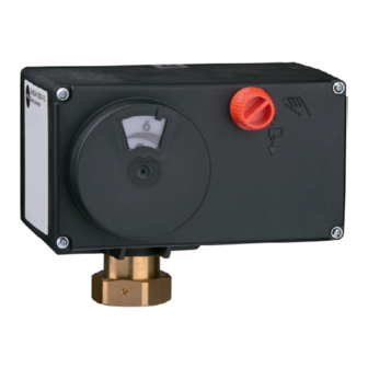
Markings on the Device
Nameplate Overview
Description of the information presented on the actuator's nameplate.
Firmware Version Details
Details on the history and changes between different firmware versions.
Design and Principle of Operation
Actuator Types and Fail-Safe Action
Explains Type 5824 and Type 5825 actuators, including fail-safe mechanisms.
Communication and Additional Equipment
Details serial interface, communication, and optional components like limit contacts.
Technical Data
Comprehensive technical specifications for Type 5824 actuators.
Dimensions in mm
Provides dimensional drawings and measurements for the actuators.
Shipment and On-Site Transport
Accepting Delivered Goods
Procedures for receiving and inspecting the delivered actuator.
Removing Packaging and Transporting
Steps for unpacking, transporting, and storing the actuator safely.
Installation
Installation Conditions and Preparation
Requirements for mounting orientation, environment, and actuator preparation.
Aligning the Travel Indication Scale
Instructions for adjusting the travel indication scale.
Mounting the Actuator
Steps for attaching the actuator to the valve using different methods.
Installing the Control Valve
Guidance on integrating the control valve into the pipeline.
Electrical Connection
Detailed instructions and warnings for wiring the actuator.
Operation Overview
Device Controls and LED Indicators
Identifies external controls and explains LED status indications.
Direction of Action and Function Switches
How switches determine actuator movement direction and input signal range.
Start-up and Configuration
Initializing the Actuator
Procedure for initial setup and zero calibration of the actuator.
Configuring the Actuator with TROVIS-VIEW
Using TROVIS-VIEW software for actuator configuration.
Adjusting the Limit Contacts
Steps for setting the limit contacts for desired switching points.
Detailed Operation
Positioner and LED Blinking Patterns
Explains positioner function and various LED blinking patterns for status and errors.
Manual Mode and Override
Describes manual operation via handwheel or Allen key.
Operation Using Memory Pen
How to use a memory pen for configuration and data logging.
Command Mode and TROVIS-VIEW Readings
Using command mode and viewing operating values, states, messages, and statistics.
Malfunctions
Troubleshooting Guide
Table of common errors, possible reasons, and recommended actions.
Error Indication by LEDs
Explains LED blinking patterns indicating specific error conditions.
Servicing
Maintenance and Warranty Information
Notes on factory checks, warranty voidance, and no maintenance requirement.
Decommissioning
Safety Precautions for Decommissioning
Procedures and safety warnings for safely taking the actuator out of operation.
Removal
Removal Procedures (Force-locking and Form-fit)
Step-by-step instructions for removing the actuator from the valve.
Repairs
Returning Actuators for Service
Guidelines for contacting after-sales service and returning defective actuators.
Disposal
Product Disposal and Recycling
Information on proper disposal, compliance with regulations, and recycling options.
Certificates
EU Declaration of Conformity
EU declarations of conformity for Type 5824 and Type 5825 actuators.
TR CU Certificate
Certificate of conformity for the Eurasian Economic Union market.
Declaration of Incorporation
Declaration stating the product is an incomplete machine per Machinery Directive.
Annex A (Configuration Instructions)
Input Signal Configuration
Details on setting input signal range, including split-range operation.
Position Feedback Signal Configuration
Adjusting the span of the position feedback signal.
Function Settings: Input Signal Failure & End Position Guiding
Configuring input signal failure detection and end position guiding.
Function Settings: Blockage, Travel, Velocity
Settings for blocking protection, limited travel, and velocity adjustments.
Function Settings: Dead Band, Characteristic, Start-up
Configuring dead band, characteristic types, and start-up procedures.
Manual Level and Other Functions
Using manual level, performing reset, zero calibration, and transit time measurement.
Annex B (Accessories and Service)
Available Accessories
List of hardware accessories and software for the actuators.
After-Sales Service and Support
Contact information for after-sales service, required specifications, and website resources.
Configuration List and Customer-Specific Data
Table detailing default settings, adjustment ranges, and settings for functions.
Need help?
Do you have a question about the 5825-30 and is the answer not in the manual?
Questions and answers