
Related Manuals for Samson 5825-20


Summarization of Contents
Safety Instructions and Measures
Intended Use of Electric Actuators
Details the proper applications and limitations for Type 5824 and 5825 Electric Actuators.
Foreseeable Misuse of Actuators
Lists applications and activities that are not suitable or compliant with the intended use.
Qualifications for Operating Personnel
Specifies the training and qualification requirements for personnel handling the actuators.
Personal Protective Equipment (PPE)
Information on required personal protective equipment for handling actuators and control valves.
Unauthorized Revisions and Modifications
States that unauthorized revisions or modifications are not permitted by SAMSON.
Actuator Safety Features
Explains the function of limit switches and fail-safe action for Type 5825.
Warning About Residual Hazards
Advises on preventing hazards from process medium, pressure, or moving parts.
Operator Responsibilities
Outlines the operator's duties regarding safe use, compliance, and instruction of personnel.
Operating Personnel Responsibilities
Defines the operating personnel's obligations for understanding instructions and safety regulations.
Referenced Standards and Regulations
Lists relevant EU directives, EAC regulations, and standards applicable to the actuators.
Referenced Documentation
Lists additional mounting and operating instructions for compatible SAMSON valves.
Severe Personal Injury Risks
Details risks of fatal injury from electric shock and bursting in pressure equipment.
Personal Injury Risks
Covers crush hazards from moving parts and risks from illegible markings or labels.
Property Damage Risks
Highlights risks of damage from excessive supply voltage, tightening torques, or manual adjustment.
Device Markings and Nameplate
Nameplate Information
Explains the various labels and identifiers found on the actuator's nameplate.
Firmware Version History
Details the changes made in different firmware versions (e.g., 1.03, 1.04, 1.10, 1.11).
Design and Principle of Operation
Fail-Safe Action Explanation
Explains the fail-safe mechanism for Type 5825, where the actuator stem moves to a specific position on power failure.
Communication Interfaces
Details the RS-232 serial interface for communication with TROVIS-VIEW software.
Additional Equipment Options
Explains limit contacts as an optional feature for 24 V versions, not retrofittable.
Technical Data Specifications
Provides detailed technical specifications for Type 5824 actuators, including travel, speed, thrust, and voltage.
Physical Dimensions
Illustrates the physical dimensions of Type 5824 and 5825 actuators with and without yokes.
Shipment and On-Site Transport
Accepting Delivered Goods
Instructions for comparing shipment with delivery note and checking for transport damage.
Removing Actuator Packaging
Guidance on when to remove packaging and checking the scope of delivery.
Transporting the Actuator
Recommendations for protecting the actuator during transport and observing temperature limits.
Lifting the Actuator
Notes that lifting equipment is not required due to the actuator's low service weight.
Storing the Actuator
Provides instructions and warnings regarding proper storage to prevent actuator damage.
Installation Procedures
Installation Conditions
Defines the work position and mounting orientation requirements for actuator installation.
Preparation Before Installation
Details checks for actuator damage and preparation of necessary tools and materials.
Aligning Travel Indication Scale
Explains how to align the travel indication scale based on the valve type.
Mounting the Actuator
Describes how to mount the actuator directly onto the valve or using a yoke.
Installing Valve into Pipeline
Instructs to install the valve according to its specific mounting and operating instructions.
Electrical Connection Guide
Provides safety warnings and instructions for connecting the actuator's electrical wiring.
Actuator Operation
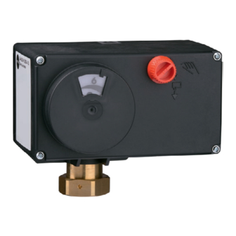
Device Overview and Controls
Identifies the external operating elements: travel indication scale and handwheel.
LED Status Indicators
Explains the meaning of red and yellow LEDs and their blinking patterns for different operating states.
Direction of Action Switch
Details how the switch position determines the actuator's direction of action based on input signal changes.
Function Switch Settings
Explains the function switch's role in determining input signal range and starting initialization.
Start-Up and Configuration
Initializing the Actuator
Describes the procedure for initializing the actuator to achieve correct position feedback.
Configuring the Actuator
Explains how to configure the actuator using the TROVIS-VIEW software via the serial interface.
Adjusting Limit Contacts
Details how to adjust the limit contacts using cam disks and adjusters for make or break contacts.
Actuator Operation Modes
Positioner Functionality
Explains that the actuator stem position directly follows the input signal.
Interpreting LED Blinking Patterns
Provides explanations for the blinking patterns of the red and yellow LEDs during various operations.
Manual Operation Modes
Details how to operate the actuator stem manually using the handwheel or an Allen key.
Operation with Memory Pen
Explains how to use a memory pen for configuration data transfer, copying, and data logging.
Troubleshooting Malfunctions
Error Indication via LEDs
Describes LED blinking patterns that indicate specific errors like limit contact issues or EEPROM faults.
Emergency Action Procedures
Outlines emergency actions for valve failure, especially for actuators with fail-safe action.
Actuator Removal
Removal: Force-Locking Attachment
Step-by-step instructions for removing the actuator with a force-locking attachment.
Removal: Form-Fit Attachment
Step-by-step instructions for removing the actuator with a form-fit attachment.
Repairs and Returns
Returning Actuators to SAMSON
Procedures for returning defective actuators to SAMSON for examination and service.
Annex A: Configuration Instructions
Input Signal Configuration
Details how the input signal (voltage or current) determines actuator stem position and range values.
Split-Range Operation
Explains how to adapt input signal ranges for parallel operation of multiple actuators.
Position Feedback Signal
Describes adjusting the position feedback signal span and its role in indicating actuator stem position.
Detect Input Signal Failure
Details the function to detect and react to input signal failures, including LED indication.
End Position Guiding Configuration
Explains the end position guiding function for earlier stem movement based on input signal thresholds.
Blockage Protection
Explains the blocking protection feature to prevent valve seizing and its indication via yellow LED.
Travel Adjustment Settings
Covers limited travel range, travel adjustment (absolute/relative), and idle time settings.
Velocity Settings
Details the three speed levels (Slow, Standard, Fast) and transit time calculation.
Dead Band Configuration
Explains the dead band setting, which determines actuator sensitivity to input signal changes.
Characteristic Curve Settings
Describes how to set the relationship between input signal and actuator stem position (Linear, Equal Percentage, etc.).
Starting Up the Actuator
Instructs to start initialization via the 'Service' folder ('Start-up').
Service Folder Functions
Lists available functions in the 'Service' folder like Manual level, error messages, and LED activation.
Annex B: Accessories and Service
Available Accessories
Lists hardware accessories like memory pens, cables, adapters, and software like TROVIS-VIEW.
After-Sales Service Contact
Provides contact information, email, and required specifications for after-sales support.
Configuration List and Customer Data
Presents a detailed list of configuration parameters, default settings, and adjustment ranges.
Need help?
Do you have a question about the 5825-20 and is the answer not in the manual?
Questions and answers