
Related Manuals for Supermicro SuperChassis 116AC2-R706WB


Summarization of Contents
Preface
About This Manual
Manual introduction for system integrators and PC technicians.
Manual Organization
Chapter 1 Introduction
Outlines the structure and content of the introduction chapter.
Chapter 2 Standardized Warning Statements for DC Systems
Outlines the structure and content of the warnings chapter.
Chapter 3 Chassis Components
Outlines the structure and content of the chassis components chapter.
Chapter 4 System Interface
Outlines the structure and content of the system interface chapter.
Chapter 5 Chassis Setup and Maintenance
Outlines the structure and content of the setup and maintenance chapter.
Chapter 6 Rack Installation
Outlines the structure and content of the rack installation chapter.
Chapter 1 Introduction
1-1 Overview
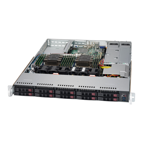
Describes the SC116 1U chassis features, cooling, and drive bays.
1-2 Shipping List
Lists shipping information and part numbers for chassis models.
1-3 Chassis Features
Details hard drive bays, PCI slots, and other chassis features.
1-4 Contacting Supermicro
Provides contact information for Supermicro headquarters, Europe, and Asia-Pacific.
1-5 Returning Merchandise for Service
Outlines the procedure for returning products for warranty service.
Chapter 2 Standardized Warning Statements for DC Systems
2-1 About Standardized Warning Statements
Explains the purpose of standardized warnings and where to find them.
Circuit Breaker
Details the requirements for the circuit breaker protection.
Power Disconnection Warning
Warns to disconnect all power sources before accessing chassis interior.
Equipment Installation
States that only trained and qualified personnel should install equipment.
Restricted Area
Warns that the unit is for installation in restricted access areas.
Battery Handling
Warns about the danger of battery explosion if replaced incorrectly.
Redundant Power Supplies
Warns that the unit may have multiple power supply connections.
Backplane Voltage
Warns about hazardous voltage/energy on the backplane during operation.
Comply with Local and National Electrical Codes
States that equipment installation must comply with local and national electrical codes.
Product Disposal
Advises handling product disposal according to national laws and regulations.
Hot Swap Fan Warning
Warns that fans may still be turning when removing the fan assembly.
DC Power Supply
Advises using approved wiring terminations for stranded wiring.
DC Power Disconnection
Instructs to ensure power is removed from the DC circuit before proceeding.
Hazardous Voltage or Energy Present on DC Power Terminals
Warns of hazardous voltage or energy on DC power terminals.
Chapter 3 Chassis Components
3-1 Overview
Introduces the chapter covering chassis components and their functions.
3-2 Components
Details the Chassis, Backplane, Fans, and Mounting Rails.
3-3 Where to get Replacement Components
Advises purchasing replacement parts from authorized Supermicro distributors.
Chapter 4 System Interface
4-1 Overview
Introduces LEDs and their meanings for system status.
4-2 Control Panel Buttons
Details the function of the power on/off and UID buttons.
4-3 Control Panel LEDs
Explains the Universal Information LED states and their indications.
4-4 Drive Carriers
Describes the SAS/SATA drives and their corresponding LEDs.
4-5 Power Supply LEDs
Explains the LED indicators for the power supply unit states.
Chapter 5 Chassis Setup and Maintenance
5-1 Overview
Introduces the chapter on component installation and maintenance procedures.
5-3 Removing the Chassis Cover
Provides step-by-step instructions for removing the chassis cover.
5-4 Installing and Removing Hard Drives
Details the procedure for installing and removing hot-swappable hard drives.
5-5 Removing the Backplane
Explains how to remove the backplane from the chassis.
5-6 Backplane Installation
Provides step-by-step instructions for installing the backplane.
5-7 Installing the Motherboard
Covers installing the motherboard, including standoffs.
Expansion Card Setup
Details how to set up expansion cards and riser cards.
5-8 Installing the Air Shroud
Explains how to install the air shroud to maximize fan efficiency.
Checking the Airflow
Provides steps to check for unobstructed airflow and system status LEDs.
5-9 System Fans
Describes the system fans and how to add or replace them.
5-10 Power Supply
Details the redundant power supplies and how to replace them.
Chapter 6 Rack Installation
6-1 Overview
Introduces the chapter on installing the system into a rack.
6-2 Unpacking the System
Details how to inspect the chassis upon arrival and choose a location.
6-3 Preparing for Setup
Covers rail assemblies, mounting brackets, and choosing a setup location.
Rack Precautions
Lists precautions for rack installation stability and safety.
General Server Precautions
Provides general safety precautions for installing server components.
Rack Mounting Considerations
Discusses ambient temperature, airflow, mechanical loading, and grounding.
6-4 Rack Mounting Instructions
Provides information on installing the SC116 into a rack unit with rails.
Identifying the Sections of the Rack Rails
Explains the components of the rack rail assemblies.
Inner Rail Extension (Optional)
Describes the optional inner rail extensions and how to install them.
Outer Rails
Details how to assemble and install the outer rails.
Installing the Chassis into a Rack
Guides on aligning and sliding the chassis into the rack rails.
Installing the Chassis into a Telco rack
Explains how to install the chassis into a Telco or post-style rack.
Appendix A SC116 Chassis Cables
A-1 Overview
Introduces the appendix listing supported cables for the system.
A-2 Cables Included with SC116 Chassis (SAS/SATA)
Details cables included for specific SC116TQ and SC116AC models.
A-3 Compatible Cables
Lists compatible cables, including alternate SAS/SATA cables.
Extending Power Cables
Provides a chart for power cable extenders based on pin count.
Front Panel to the Motherboard
Lists ribbon cables for connecting the front panel to the motherboard.
Appendix C BPN-SAS-116TQ Backplane Specifications
C-1 ESD Safety Guidelines
Offers guidelines for protecting equipment from Electrostatic Discharge (ESD).
C-2 General Safety Guidelines
Provides general safety guidelines for component installation and removal.
C-3 An Important Note to Users
Notes that images may differ from the actual received card.
C-4 Introduction to the BPN-SAS-116TQ Backplane
Introduces the BPN-SAS-116TQ backplane's design and performance.
C-5 Rear Connectors
Details the connectors located on the rear side of the backplane.
C-6 Rear Connector and Pin Definitions
Defines pin assignments for backplane power, upgrade, sideband, and SAS/SATA connectors.
C-7 Rear Jumper Locations and Pin Definitions
Explains jumper locations and their pin definitions for backplane configuration.
C-8 Front Connectors and LED Indicators
Details front connectors and their associated SAS/SATA drive and failure LEDs.
Appendix D BPN-SAS3-116A Backplane Specifications
D-1 ESD Safety Guidelines
Offers guidelines for protecting equipment from Electrostatic Discharge (ESD).
D-2 General Safety Guidelines
Provides general safety guidelines for component installation and removal.
D-3 A Note to Users
Notes that images may differ from the actual received PCB revision.
D-4 Rear Connectors
Details the connectors located on the rear side of the backplane.
D-5 Rear Connector Definitions
Defines pin assignments for backplane power, upgrade, SAS, and sideband connectors.
D-6 Rear Jumper
Explains jumper locations and their pin definitions for backplane configuration.
D-7 Front Connectors and LED Indicators
Details front connectors and their associated HDD activity and failure LEDs.
Appendix E BPN-SAS3-116A-N2 Backplane Specifications
E-1 ESD Safety Guidelines
Offers guidelines for protecting equipment from Electrostatic Discharge (ESD).
E-2 General Safety Guidelines
Provides general safety guidelines for component installation and removal.
E-3 Version Information
Provides version information for the BPN-SAS3-116A-N2 backplane manual.
E-4 Rear Connector Locations
Details the connectors located on the rear side of the backplane.
E-5 Rear Connector Definitions
Defines pin assignments for power, DC input, sideband, SAS, and NVMe connectors.
E-6 Rear Jumpers
Explains jumper locations and their pin definitions for backplane configuration.
E-7 Front Connectors and LED Indicators
Details front connectors and their associated HDD activity and failure LEDs.
Need help?
Do you have a question about the SuperChassis 116AC2-R706WB and is the answer not in the manual?
Questions and answers