Table of Contents
Advertisement
Quick Links
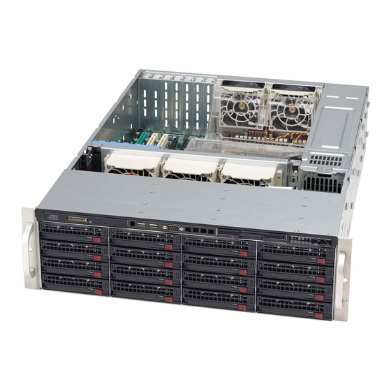
SC836 Chassis Series
SC836BE1C-R1K03B
SC836BHA-R1K28B
SC836BHE26-R1K28B
SC836BE26-R1K28B
SC836BE16-R920B
SC836BA-R920B
SC836E16-R500B
SC836E26-R1200B
SC836BE1C-R1K23B
SC836TQ-R800V / SC836TQ-R800B
USER'S MANUAL
SC836BE2C-R1K03B
SC836BHE16-R1K28B
SC836BE16-R1K28B
SC836BA-R1K28B
SC836BE26-R920B
SC836TQ-R500B
SC836E16-R1200B
SC836A-R1200B
SC836TQ-R710B
Revision 2.2
Advertisement
Table of Contents

Related Manuals for Supermicro SuperChassis 836BE1C-R1K23B


Summarization of Contents
Preface
About this Manual
Manual's purpose and intended audience.
Warnings
Symbols and general warnings used within the manual.
Contacting Supermicro
Contact information for Supermicro headquarters, Europe, and Asia-Pacific.
Chapter 1 Introduction
1-1 Overview
General description of the SC836 chassis and its features.
1-2 Shipping List
Information on obtaining the latest shipping lists and part numbers.
1-3 Chassis Features
Details about the SC836 chassis's physical and functional characteristics.
1-4 Returning Merchandise for Service
Procedure for returning products for warranty service.
1-5 Where to get Replacement Components
Guidance on purchasing replacement parts and components.
Chapter 2 Standardized Warning Statements for AC Systems
About Standardized Warning Statements
Introduction to industry standard warnings for user safety.
Installation Instructions
Instructions to follow before connecting the system to the power source.
Circuit Breaker
Requirement for building's short-circuit protection device rating.
Power Disconnection Warning
Critical safety warning about disconnecting power before servicing.
Equipment Installation
Guidelines stating that only trained and qualified personnel should install equipment.
Restricted Area
Information that the unit is intended for installation in restricted access areas.
Battery Handling
Warning regarding the danger of battery explosion if replaced incorrectly.
Redundant Power Supplies
Warning that all power connections must be removed to de-energize the unit.
Backplane Voltage
Warning about hazardous voltage or energy on the backplane during operation.
Comply with Local and National Electrical Codes
Requirement to comply with local and national electrical codes for installation.
Product Disposal
Guidelines for handling the ultimate disposal of the product according to laws.
Hot Swap Fan Warning
Warning about fans potentially still turning when removing the fan assembly.
Power Cable and AC Adapter
Warning about using only provided/designated cables and adapters to prevent malfunction or fire.
Chapter 3 System Interface
3-1 Overview
Overview of the server's control panel, hard drives, and power supply status lights.
3-2 Control Panel Buttons
Description of the chassis's push-buttons that control system power.
3-3 Control Panel LEDs
Explanation of the six system status LEDs on the control panel.
Information LED
Alerts operator of several states like overheat, fan failure, or power failure.
Chapter 4 Chassis Setup and Maintenance
4-1 Overview
Covers component installation and chassis maintenance procedures.
4-2 Removing Power from the System
Procedure to ensure power is removed before setup or maintenance.
4-3 Removing the Chassis Cover
Step-by-step guide to safely remove the chassis cover.
4-4 Installing Hard Drives
Instructions for installing hot-swap drives into the chassis.
4-5 Expansion Cards
Details on installing full-height, full-length expansion cards into PCI slots.
4-6 Installing the Air Shroud
Instructions for installing the air shroud to optimize fan effectiveness.
4-7 System Fans
Information on the chassis's hot-swappable fans and their replacement.
4-8 Power Supply
Details on the chassis's redundant, hot-swappable power supply units.
Chapter 5 Rack Installation
5-1 Unpacking the System
Instructions for inspecting the system upon unpacking for any shipping damage.
5-2 Preparing for Setup
Guidance on selecting a suitable location and preparing the rack unit.
Choosing a Setup Location
Recommendations for rack placement, clearance, and environmental considerations.
5-3 Warnings and Precautions
Safety warnings and precautions for rack installation and server handling.
5-4 Installing the System into a Rack
Step-by-step instructions for installing the server into a rack using provided rails.
Identifying the Sections of the Rack Rails
How to identify the inner and outer rails for chassis installation.
Releasing the Inner Rail
Procedure for releasing the inner rail from the outer rails for mounting.
Installing the Inner Rails on the Chassis
Steps to attach the inner rails to the chassis.
Installing the Outer Rails onto the Rack
Process for mounting the outer rails onto the rack structure.
Sliding the Chassis onto the Rack Rails
Instructions for safely sliding the chassis onto the installed rack rails.
Appendix A Chassis Cables
A-1 Standard and Optional Cables for SC836 Models
Tables listing included and optional cables by model and part number.
A-2 SAS Cables
Lists optional compatible SAS cables for various motherboard SAS connectors.
A-3 Extending Power Cables
Chart for selecting power cable extenders based on pin count and length.
A-4 Front Panel to the Motherboard
List of cables for connecting the chassis front panel to the motherboard.
Appendix C Backplane Specifications
C-1 Overview
Details about backplanes used in various SC836 chassis models.
C-2 Safety Guidelines
ESD and general safety guidelines for handling backplanes.
C-3 BPN-SAS-836A Backplane
Pin definitions and layout for the BPN-SAS-836A backplane.
C-4 BPN-SAS-836TQ Backplane
Connector and component layout for the BPN-SAS-836TQ backplane.
C-5 BPN-SAS2-836EL Backplane and SAS2 JBOD Configuration
Information on BPN-SAS2-836EL backplanes and SAS2 JBOD setups.
C-6 BPN-SAS3-836EL Backplane and SAS3 JBOD Configuration
Details on BPN-SAS3-836EL backplanes and SAS3 JBOD configurations.
Appendix D SC836B Added Features
D-1 Identifying the Drive Kit Components
Identification of components included in the rear drive kit for SC836B models.
D-2 Installing the Drive Cage
Steps to install the rear hard drive cage and its backplane.
D-3 Installing Hard Drives in the Rear Drive Carriers
Procedure for installing 2.5" hard drives into the rear drive carriers.
D-4 Installing Hard Drives into the Rear Drive Bays
Instructions for inserting the hard drive carrier into the rear drive bay.
D-5 Removing Drives From the Rear Drive Bays
Steps to remove hard drives and carriers from the rear drive bays.
Appendix E CSE-PTJBOD-CB3 Control Board
E-1 Overview
Introduction to the CSE-PTJBOD-CB3 JBOD control board and its capabilities.
E-2 Safety Guidelines
ESD and general safety guidelines for handling the JBOD control board.
E-3 Components, Connectors, Jumpers and LEDs
Identification and location of components, connectors, jumpers, and LEDs on the CSE-PTJBOD-CB3.
Connectors Jumpers and LED Indicators
Details on front SAS2/SAS3 and SC847D jumpers and their settings.
SC847D JBOD Chassis Cabling
Diagram for connecting the CB3 power board to SC847D JBOD chassis backplanes.
E-5 JBOD Power Up/Power Down Sequences
Procedures for powering up and powering down the JBOD system.
E-6 IPMI Static IP to DHCP Setting
Steps to configure the CB3 control board from static IP to DHCP mode.
Need help?
Do you have a question about the SuperChassis 836BE1C-R1K23B and is the answer not in the manual?
Questions and answers