
Related Manuals for Supermicro SuperChassis 116AC2-R706WB2


Summarization of Contents
Preface
About This Manual
Details the purpose and audience of this user manual.
Manual Organization
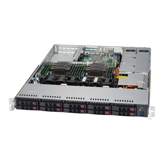
Introduction
Provides an overview of the SC116 1U chassis features.
Shipping List
Lists the components included in the SC116 chassis package.
Chassis Features
Details the key features of the SC116 1U high-performance chassis.
Contacting Supermicro
Provides contact information for Supermicro headquarters, Europe, and Asia-Pacific.
Returning Merchandise for Service
Outlines the procedure for returning products for warranty service.
Standardized Warning Statements for DC Systems
About Standardized Warning Statements
Explains industry-standard warnings for user safety and potential hazards.
Circuit Breaker
Specifies the required rating for the short-circuit protection device.
Power Disconnection Warning
Instructs users to disconnect all power sources before accessing the chassis.
Equipment Installation
Emphasizes that only trained personnel should install or service equipment.
Restricted Area
Notes that the unit is intended for installation in restricted access areas.
Battery Handling
Warns about the danger of explosion if batteries are replaced incorrectly.
Redundant Power Supplies
Advises to remove all power connections to de-energize units with multiple power supplies.
Backplane Voltage
Warns of hazardous voltage on the backplane during operation.
Comply with Local and National Electrical Codes
States that installation must comply with local and national electrical codes.
Product Disposal
Mandates handling product disposal according to national laws and regulations.
Hot Swap Fan Warning
Alerts that fans may still be turning when removing the fan assembly.
DC Power Supply
Guides on using approved wiring terminations for stranded wiring.
DC Power Disconnection
Emphasizes ensuring power is removed from the DC circuit before procedures.
Hazardous Voltage or Energy Present on DC Power Terminals
Warns of hazardous voltage/energy on DC power terminals and to replace covers.
Chassis Components
Overview
Describes the most common components included with your chassis.
Component Details
Lists chassis, backplane, fans, mounting rails, power supply, and air shroud.
System Interface
Overview
Explains LEDs on the control panel and drive carriers for system status.
Control Panel Buttons
Details the power and UID buttons on the front panel.
Control Panel LEDs
Describes the Universal Information LED states and their meanings.
Drive Carriers
Details the SAS/SATA drives and their respective drive carrier LEDs.
Power Supply LEDs
Explains the LED indicators for power supply status (on/off/temperature).
Chassis Setup and Maintenance
Overview
Covers steps for installing components and performing chassis maintenance.
Installation and Maintenance Procedures
Lists procedures for component installation and general system maintenance.
Removing the Chassis Cover
Provides step-by-step instructions for removing the chassis cover.
Installing and Removing Hard Drives
Details the process for installing and removing hot-swappable hard drives.
Removing the Backplane
Guides on how to safely remove the backplane from the chassis.
Backplane Installation
Provides instructions for installing the backplane into the chassis.
Installing the Motherboard
Explains how to install the motherboard, including standoffs.
Expansion Card Setup
Describes how to install expansion cards using riser cards.
Installing the Air Shroud
Details the installation process for the air shroud.
Checking the Airflow
Provides guidance on ensuring proper airflow within the chassis.
System Fans
Covers adding and replacing system fans for optimal cooling.
Power Supply
Explains redundant power supplies and how to replace a failed unit.
Rack Installation
Overview
Provides a quick setup guide for installing the system into a rack.
Unpacking the System
Instructs on inspecting the chassis for damage upon arrival.
Preparing for Setup
Details necessary items and initial steps for rack installation preparation.
Rack Precautions
Lists safety precautions for installing equipment in a rack.
General Server Precautions
Provides general safety precautions for server installation in racks.
Rack Mounting Considerations
Discusses factors like temperature, airflow, and loading for rack mounting.
Rack Mounting Instructions
Guides on identifying and assembling the chassis rack rail components.
Inner Rail Extension (Optional)
Details how to attach optional inner rail extensions for chassis stabilization.
Outer Rails
Provides instructions for assembling and installing the outer rail components.
Installing the Chassis into a Rack
Guides on sliding the chassis with its rails into the server rack.
Installing the Chassis into a Telco rack
Explains the process of installing the chassis into a Telco or post-style rack.
Appendix A: Chassis Cables
Overview
Lists supported cables for the SC116 chassis system.
Cables Included with SC116 Chassis (SAS/SATA)
Details cables provided with specific SC116 chassis models (SAS/SATA).
Compatible Cables
Lists alternate SAS/SATA cables for motherboards with different connectors.
Appendix B: Power Supply Specifications
700W (80 PLUS Gold Certified)
Lists specifications for the 700W 80 PLUS Gold Certified power supply.
700W/750W (80 PLUS Platinum Certified)
Lists specifications for the 700W/750W 80 PLUS Platinum Certified power supply.
Appendix C: BPN-SAS-116TQ Backplane Specifications
ESD Safety Guidelines
Provides guidelines for preventing Electrostatic Discharge (ESD) damage.
General Safety Guidelines
Covers general safety practices for handling computer components.
An Important Note to Users
Notes that graphics may differ from the actual received product.
Introduction to the BPN-SAS-116TQ Backplane
Introduces the BPN-SAS-116TQ backplane and its design.
Rear Connectors and Pin Definitions
Identifies rear connectors and their pin definitions on the backplane.
Rear Jumper Locations and Pin Definitions
Details rear jumper locations and their corresponding pin definitions.
Front Connectors and LED Indicators
Maps front connectors and LEDs to SAS/SATA drive numbers and activity.
Appendix D: BPN-SAS3-116A Backplane Specifications
ESD Safety Guidelines
Provides guidelines for preventing Electrostatic Discharge (ESD) damage.
General Safety Guidelines
Covers general safety practices for handling computer components.
A Note to Users
Notes that graphics may differ from the actual received product.
Rear Connectors and Definitions
Identifies rear connectors and their definitions on the backplane.
Rear Jumper
Details rear jumper locations and their corresponding settings.
Front Connectors and LED Indicators
Maps front connectors and LEDs to SAS/SATA drive numbers and activity.
Appendix E: BPN-SAS3-116A-N2 Backplane Specifications
ESD Safety Guidelines
Provides guidelines for preventing Electrostatic Discharge (ESD) damage.
General Safety Guidelines
Covers general safety practices for handling computer components.
Version Information
Provides version information for the BPN-SAS3-116A-N2 manual.
Rear Connector Locations
Identifies rear connector locations on the backplane.
Rear Connector Definitions
Details rear connector definitions for power, NVMe, and sideband connections.
Rear Jumpers
Details rear jumper settings for NVMe mapping and manufacturing use.
Front Connectors and LED Indicators
Maps front connectors and LEDs to SAS/SATA/NVMe drive numbers and activity.
Need help?
Do you have a question about the SuperChassis 116AC2-R706WB2 and is the answer not in the manual?
Questions and answers