Advertisement
Quick Links
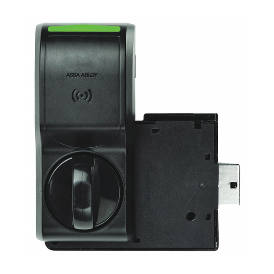
Package Contents
Lock Reader
Interface Cable,
System Side
Recommended Tools
Drill, Drill bits: 5/32", 1/2"
Approved Credential:
i.e. iCLASS or Prox ID card
Specifications
Voltage: 12–24 VDC ±10% (Power Supply not provided)
K200-622 (Reader) Current Consumption:
12 VDC:
24 VDC:
Operating Temperature: -10C to 50C
Holding Force: 250 lbs
Part Number 3085006.001, Rev. B
K200-622
Cabinet Lock Series
Installation Instructions
Mounting
Template
Machine
screw with
Strike Plate
washer
Lock Body
Double door bracket
Phillips drivers P0, P2
Pencil, Wire Stripper
38 mA peak for Red and Green LED only
226 mA peak for Red and Green LED and Motor Drive
17 mA peak for Red and Green LED only
118 mA peak for Red and Green LED and Motor Drive
Key Override Paddle
2-56x3/8"
6 x 1/2"
2X
3X
6-32 screws
5/16"
3X
1"
1-1/4"
1-5/8"
2X
1-3/4"
2X
1X
2X
Interface Cable, Lock Side
Optional:
Cam lock for key override
HES, Inc.
Phoenix, AZ
1.800.626.7590
www.hesinnovations.com
Shaft Extension
0-80x½"
2-56x1-1/4"
1X
1X
1-7/8"
2‐1/2"
2X
2X
1
Advertisement

Related Manuals for HES K200-622-B2


Summary of Contents for HES K200-622-B2
- Page 1 K200-622 HES, Inc. Cabinet Lock Series Phoenix, AZ 1.800.626.7590 Installation Instructions www.hesinnovations.com Package Contents Key Override Paddle Lock Reader Mounting Template Shaft Extension 2-56x3/8” 6 x 1/2” 0-80x½” 2-56x1-1/4” Machine screw with 6-32 screws Strike Plate washer Interface Cable, System Side 5/16”...
- Page 2 External Interface Signals Summary: Lock Signal Lock Signal From/To Direction and Wire Electrical Interface Logic Name Color P1-1/J1-1 Input, Power to Reader Input Power Red/24 AWG P1-12/J1-2 Open = Unlocked Tamper / Door Output, Dry Contact Position + Yellow/24 AWG (0–35 VDC, <100mA) Closed = Locked P1-3/J1-3...
- Page 3 SYSTEM OVERVIEW The K200-622 wired cabinet lock (K200) extends access control to a cabinet or drawer. The K200 lock is capable of reading radio-frequency identification (RFID) credentials and providing that credential data to an electronic access control (EAC) system via Wiegand data signaling. The EAC is responsible for determining whether user access should be granted or denied.
- Page 4 TRANSFER the location of the inside wall of the cabinet to the door. MEASURE the horizontal distance between the inside edge of the cabinet and the door edge. NOTE: The drawn line depicts the location of the strike mounting surface. LOCATE the lock centerline notch on the latch and MARK this point on the inside of the cabinet door using a pencil.
- Page 5 PLACE and USE the Lock/Reader Template. NOTE: The orientation will be reversed for a right hand door. CUT through line to separate the Strike Plate Template. PEEL OFF the protective layer of the Lock Template, ALIGN it to both the latch centerline and the line depicting the inside wall of cabinet, and PRESS to secure.
- Page 6 IF a Cam Lock key override will be used, AND the orientation allows for installation, THEN INSTALL the Key Override Paddle. INSERT the paddle’s arm into the opening shown, and ALIGN the rails of the paddle to the ones on the lock. SLIDE the paddle gently until it stops.
- Page 7 INSTALL the lock. REMOVE the cover from lock. PLACE the lock on the inside of the door, threading the cable through the lock. ATTACH the lock to the antenna/reader using two 8-32 [4.00 mm] lock mount screws (see Table 2 for length), and TIGHTEN the screws.
- Page 8 CONNECT the antenna/reader wire to the lock body. NOTE: The antenna/reader wire connector is engineered to fit only one way. INSERT the antenna/reader wire connector, ensuring correct orientation TUCK excess cable into the lock body. ATTACH the cover. CONNECT the 10-position Molex Micro-Fit Cable between the K200 and the EAC. Part Number 3085006.001, Rev.
- Page 9 NOTE: It is recommended that 10-conductor, 24 AWG, cable be used. ENSURE the following power cabling guidelines are followed: Wire AWG Supply Voltage Allowed Cable Length (ft.)* 20 AWG 6679 22 AWG 4201 24 AWG 2641 * Round trip loss. V = 2 x I x R x xft xft = V / (2 x I x R) POSITION the cable out of the way, as required.
-
Page 10: Fcc Statement
INSTALL for the double-door strike plate mounting bracket. (OPTIONAL) NOTE: The double-door strike plate bracket requires that one door can be secured. PLACE the bracket on door, making sure it aligns with the mark made in Step 2c and the edge of the door. MARK the door. -
Page 11: Conformité Aux Normes Fcc
CE Statement HES hereby declares that these proximity readers are in compliance with the essential requirements and other relevant provisions of Directive 1999/5/EC (http://ec.europa.eu/enterprise/sectors/rtte/files/guide2009-04-20_en.pdf). Conformité aux normes FCC Cet appareil est confrome à la Partie 15 des règlements de la FCC. Son fonctionnement est souimes aux deux conditions suivantes: (1) cet appareil ne peut causer d’interférences, et... - Page 12 For Technical Support please call 1-800-626-7590 For information on other HES cabinet lock solutions, visit hesinnovations.com © 2015, Hanchett Entry Systems, Inc., an ASSA ABLOY Group Company. Part Number 3085006.001, Rev. B...
Need help?
Do you have a question about the K200-622-B2 and is the answer not in the manual?
Questions and answers