Table of Contents
Advertisement
Quick Links
KS200
(Wiegand)
Integrated Wired Server Cabinet Lock
Installation & Operating Instructions
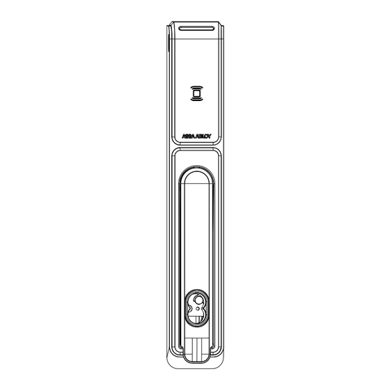
Operation
To activate the KS200/KS210 integrated electronic access control
Server Cabinet Lock, present a known/valid credential to the card
reader. For emergency override, insert a valid key in to the SFIC (Small
Format Interchangeable Core) cylinder and rotate to the unlocked
position. Upon access granted, verify functionality by lifting and
rotating the handle to release the locking cam and open the door.
NOTE: The unit shall be powered by a UL294 listed power supply or access control
output with a power limited Class 2 output. The DC input feed to the device shall be
protected by 1A max rated over current protection provided at the installation site.
ASSA ABLOY recommends the use of Securitron and Life Safety Power power
management products for use with ASSA ABLOY branded electromechanical
and integrated electronic access control locking devices.
Product Contents
A KS200/KS210 Lock Body
B Lock Interface Cable
C Rear Mounting Bracket
D Connectors (3)
E Screws (3) #8/32 x 1/4"
Pan Head Phillips
F Locking Cam
Recommended Tools
• Phillips #2 Screwdriver
• Cutting Wheel (As Required)
Recommended Accessories
• SFIC Mechanical Core and Keys
• KS-DPS Door Open/Closed Status
• CBL6-QC12 6 ft Door Interface Cable
• CBL12-QC12 12 ft System Side Interface Cable
• WT-2 Securitron Wiegand Test Box
& KS210
G Screw (1) #1/4-20 x 1/2"
Truss Head Phillips
H SFIC Cam & Spacer
I Plug-In External DPS Adapter
(Optional)
WARNING: This product can expose you to chemicals including lead, which is known to the state of California
to cause cancer and birth defects or other reproductive harm. For more information go to P65Warnings.ca.gov.
(OSDP)
Diagram 1: Product Components
A
C
H
KS200
• Contains FCC ID:
JQ6-ICLASSBTM
• Contains IC ID:
2236B-ICLASSBTM
• WPC ID: ETA-SD-20210402373
B
D
E
F
G
I
KS210
• FCC ID: VC3-KS210
• IC ID: 7160A-KS210
• WPC ID: ETA-SD-20210402371
1 of 8
Advertisement
Table of Contents

Related Manuals for HES ASSA ABLOY KS200


Summary of Contents for HES ASSA ABLOY KS200
- Page 1 KS200 & KS210 (Wiegand) (OSDP) Integrated Wired Server Cabinet Lock Installation & Operating Instructions Operation Diagram 1: Product Components To activate the KS200/KS210 integrated electronic access control Server Cabinet Lock, present a known/valid credential to the card reader. For emergency override, insert a valid key in to the SFIC (Small Format Interchangeable Core) cylinder and rotate to the unlocked position.
- Page 2 40 mA Power are determined by the end-product application. • Communication KS200 (Wiegand Max Avg 100 mA 75 mA Hereby, Hanchett Entry Systems, Inc (HES) TTL, SIAAC-01-1996) KS210 (OSDP Peak 130 mA 130 mA declares that the radio equipment type KS200/ RS-485, SIA v2.2, IEC 60839-11-5)
- Page 3 Mounting Diagram 2 Door Preparation 1. LOCATE the 6" x 1" [150 x 25 mm] lock cutout on the door. Diagram 2. 2. INSERT the KS200/KS2100 Lock Body Diagram 3 Insert Lock Body (A) into the 6" x 1" [150 x 25 mm] cutout. Make sure the unit bottom tabs grab the back of the wall.
- Page 4 7. External DPS Adapter Activation. Diagram 7. Diagram 7 DPS Activation • REMOVE the jumper on the back of the KS200/KS210 Lock Body (A). • CONNECT the 2-Pin Plug-In External DPS Adapter (I) to the back of the KS200/KS10 Lock Body. External •...
- Page 5 Cam Selection NOTE: RE-USE existing cam when possible. Diagram 10 KS Cam Length Selection 10a BACK 10b SIDE Length Depth PART NO. CAM LENGTH CAM DEPTH Included 38mm – 4 (standard) 1-1/2" [38mm] 1" [25.4mm] KS-CAM38 38mm – 1 (optional) 1-1/2"...
- Page 6 ATTENTION: Installation wiring for the product and wiring methods shall be in accordance with the National Connections & Wiring Electrical Code (NEC), ANSI/NFPA 70. Observe precautions for handling electrostatic sensitive devices. Diagram 12 Server Cabinet Wiring Example Cabinet Door 8-Pin Molex 4-Pin Molex Connector Connector...
- Page 7 Optional Quick Connect Additional OSDP Guide Information (Sold Separately) 1. CONNECT the Lock Side Interface Cable to the Available at: assaabloyesh.com/en/tech-info/digital-asset-search/ optional 6 ft Door Interface Cable (CBL6-QC12). NOTE: SEE Server Cabinet Wiring Example, Diagram 12. 1. Understanding OSDP Implementations (HID/Mercury FAQ) 2.
- Page 8 If this equipment does cause harmful interference to radio or television reception, Por el presente, HES, Inc. declara que estos lectores de which can be determined by turning the equipment proximidad cumplen con los requisites esenciales y otras off and on, the user is encouraged to try to correct the disposiciones relevantes de la Directiva 2014/53/EU.
Need help?
Do you have a question about the ASSA ABLOY KS200 and is the answer not in the manual?
Questions and answers