
Related Manuals for Lenze m850-S120


Summary of Contents for Lenze m850-S120
- Page 1 Project planning EN Geared servo motors g500-S / m850 shaft-mounted helical geared servo motor...
-
Page 3: Table Of Contents
Contents Contents About this document Document description Further documents Notations and conventions Product information Product description Identification of the products Features The modular system Designs Mounting positions Information on project planning Safety instructions Basic safety instructions Application as directed Foreseeable misuse Residual hazards General information Drive dimensioning... - Page 4 Contents Technical data Notes regarding the given data Standards and operating conditions Conformities and approvals Protection of persons and device protection EMC data Environmental conditions Data overview Radial forces and axial forces Selection tables Inverter mains connection 400 V, Self-ventilated motors Dimensions Basic dimensions Gearbox with pre-stage...
-
Page 5: About This Document
Please observe the notes in the following chapters! ▶ Safety instructions ^ 18 ▶ Information on mechanical installation ^ 39 ▶ Information on electrical installation ^ 40 Further documents Information and tools with regard to the Lenze products can be found on the Internet: www.Lenze.com à Downloads... -
Page 6: Notations And Conventions
About this document Notations and conventions Notations and conventions Conventions are used in this document to distinguish between different types of information. Numeric notation Decimal separator Point Generally shown as a decimal point. Example: 1 234.56 Warnings UL Warnings Are used in English and French. UR warnings Text Engineering Tools... -
Page 7: Product Information
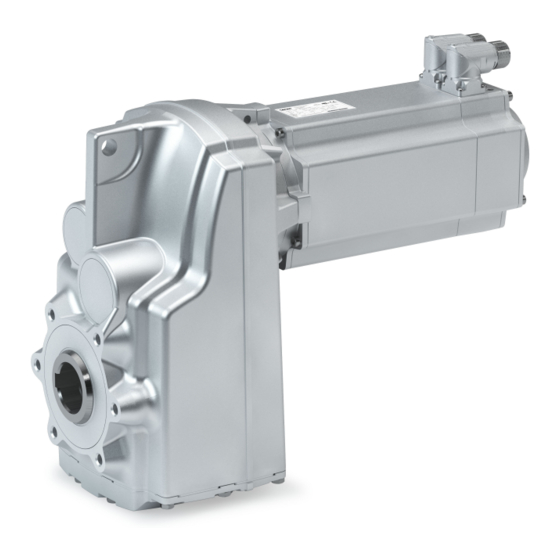
• Synchronous servo motor m850 as basis for geared motor In a power range of 2.0 to 9.2 kW, Lenze offers servo motors with an easily scalable modular design. The drives are designed for the open-loop or closed-loop controlled servo inverter operation. -
Page 8: Identification Of The Products
Product information Identification of the products Identification of the products Gearbox product name Gearbox type Product series Type Rated torque Nm Product g500-S130 g500-S220 g500-S400 g500-S660 Shaft-mounted helical g500 gearbox g500-S950 2100 g500-S2100 3100 g500-S3100 4500 g500-S4500 Product name: m850 synchronous servo motor Product range Version Flange height... -
Page 9: Features
Product information Features Features The following figure provides an overview of the elements and connections on the product. Their position, size and appearance may vary. Ventilation Temperature monitoring (depending on the mounting position) Motor connection Oil filler plug (depending on the mounting position) Remove oil control plug (depending on the mounting position) Torque support... -
Page 10: The Modular System
Product information The modular system The modular system Values printed in bold are standard designs. Values that are not printed in bold are potential extensions, some of them including a surcharge. Geared motors up to 660 Nm Gearbox g500-S130 g500-S220 g500-S400 g500-S660 Min. - Page 11 Product information The modular system Geared motors from 950 Nm to 4500 Nm Gearbox g500-S950 g500-S2100 g500-S3100 g500-S4500 Min. motor assignment m850-S120 m850-S120 m850-S120 m850-S120 Max. motor assignment m850-S190 m850-S190 m850-S190 m850-S190 Technical data Max. output torque 2100 3100 4500 Min.
-
Page 12: Designs
Product information The modular system Designs Designs Gearbox designs Observe the available gearbox designs! 4The modular system ^ 10 g500-S130 ... S660 Hollow shaft, with foot Without centring (HBR) Hollow shaft, without foot Without centring (HDR) With centering (HCR) Flange with through holes (HCK) - Page 13 Product information The modular system Designs Shrink disc, without foot Without centring (SDR) With centring (SCR) Flange with through holes (SCK) Solid shaft, with foot Without centring (VBR) Solid shaft, without foot Without centring (VDR) With centering (VCR) Flange with through holes (VCK)
- Page 14 Product information The modular system Designs g500-S950 ... S4500 Hollow shaft, with foot Without centring (HBR) With centring (HAR) Flange with through holes (HAK) Shrink disc, with foot Without centring (SBR) With centring (SAR) Flange with through holes (SAK) Solid shaft, with foot Without centring (VBR) With centring (VAR) Flange with through holes (VAK)
- Page 15 Product information The modular system Designs Models at the output Motor connection ICN connector ICN hybrid connector for One Cable Technology (OCT) Cooling: Self-ventilated Feedback Feedback and brake...
-
Page 16: Mounting Positions
Product information The modular system Mounting positions Mounting positions Details of the mounting position are needed to ensure the corresponding lubricant amount, position of the ventilation, oil checks and oil drain plug on the gearbox. To reduce the number of different versions, the following gearboxes can also be ordered with combined mounting positions: g500-S130 ... - Page 17 Product information The modular system Mounting positions Position of the ICN connectors Position of the hollow shaft with shrink disc The output flange is only available in position "F". Output flange and shrink disc are not possible in the same position.
-
Page 18: Information On Project Planning
Information on project planning Safety instructions Information on project planning Safety instructions Disregarding the following basic safety measures and safety information may lead to severe personal injury and damage to property! Observe all specifications of the corresponding documentation supplied. This is the precondition for safe and trouble-free operation and for obtaining the product features specified. -
Page 19: Basic Safety Instructions
The procedural notes and circuit details described are only proposals. It is up to the user to check whether they can be adapted to the particular applications. Lenze does not take any responsibility for the suitability of the procedures and circuit proposals described. -
Page 20: Application As Directed
Information on project planning Safety instructions Application as directed Application as directed The product must only be actuated under the operating conditions and power limits • specified in this documentation. The product meets the protection requirements of 2014/35/EU: Low-Voltage Directive. •... -
Page 21: Residual Hazards
Information on project planning Safety instructions Residual hazards Residual hazards Even if notes given are taken into consideration and protective measures are implemented, the occurrence of residual risks cannot be fully prevented. The user must take the residual hazards mentioned into consideration in the risk assessment for his/her machine/system. - Page 22 Information on project planning Safety instructions Residual hazards Motor protection Version with plug: • Never disconnect the plug when energized. The plug could be destroyed. Switch off the voltage supply or disable the inverter prior to disconnecting the plug. Installed thermal detectors are no full protection for the machine. •...
-
Page 23: General Information
• and the foundations. NOTICE A thermal check with the Drive Solution Designer (DSD) or contacting your Lenze representative is required if ▶ the input speed n > 1500 rpm is fallen below in case of the gearbox ratios given in the following. -
Page 24: Drive Dimensioning
With the «Drive Solution Designer«, you can design the drive both quickly and to a high quality. The software contains profound and proven expertise with regard to drive applications and mechatronic drive components. Please get in touch with your Lenze representative. NOTICE The dimensioning is suitable for the operating modes S1, S2, S3 and S6... - Page 25 Information on project planning Drive dimensioning Workflow S1 operation S2, S3 and S6 operation Check operating conditions Define required input variables Determine correction factor Operating modes and operating time Operating modes and operating time Ambient temperature and installation height Ambient temperature and installation height Mounting position Mounting position Mean speed utilization...
- Page 26 Information on project planning Drive dimensioning Define required input variables Necessary input variables Note Symbol Unit Operating time/day Mean speed utilization of the geared motor Relating to the load speed n Ambient temperature °C Site altitude Amsl Radial force rated Axial force rated Transmission element at the output...
- Page 27 Information on project planning Drive dimensioning Mean speed utilisation Daily operating time Mean speed utilisation relating to the load speed n 100 % 80 % 60 % 50 % 25 % Correction factor 1.0 h 1.29 1.33 1.38 1.42 1.55 2.0 h 1.15 1.20...
- Page 28 Information on project planning Drive dimensioning Determination of the required gearbox load capacity Define the required load factor at runtime t Runtime t ≤ 10 % Take the load factor k from diagram into account Runtime t > 10 % Take intensity k from calculation into account Calculate intensity...
- Page 29 Information on project planning Drive dimensioning Order data Ratio i Geared motor Example 3.267 g500-H140 m850-S120/S3960 Example 3.661 g500-S130 m850-S120/S3960 Example 4.889 g500-B240 m850-S120/S3960 Operating modes S2, S3, and S6 Calculation of the required drive power Calculation Result Unit Output torque ≥...
-
Page 30: Final Configuration
Information on project planning Final configuration Final configuration Screening Connection dimensions Output shaft Output flange/foot Mounting position Geared motor Connector/terminal box Driven shaft/output flange Product extensions Torque plate Shaft cover Connector/terminal box Brake Feedback Blower Temperature monitoring Second shaft end Handwheel Protection cover More information about the final configuration:... -
Page 31: Surface And Corrosion Protection
Various surface coatings ensure that the motors operate reliably even at high air humidity, in outdoor installation or in the presence of atmospheric impurities. Any color from the "RAL Classic" collection can be chosen for the top coat. The OKS-XL (extra Large) version requires a check by your responsible Lenze subsidiary. Surface and corrosion... -
Page 32: Lubricants
Information on project planning Final configuration Lubricants Lubricants The following gearboxes are lubricated for life: g500-S130 • Recommended lubricants: Lubricant CLP HC 220 CLP HC 320 CLP HC 46 CLP HC 220 USDA H1 USDA H1 Ambient temperature -30 … +40 °C -20 …... -
Page 33: Ventilation
Information on project planning Final configuration Ventilation Ventilation No ventilation is required for the gearboxes g500-S130 … S220. The gearbox g500-S220 can optionally be fitted with a ventilation unit. From g500-S400 onwards, the gearboxes are supplied with ventilation units as standard. - Page 34 Information on project planning Final configuration Ventilation g500-S220 ... S660 Mounting position M1 (A) Mounting position M2 (D) Mounting position M3 (B) Filling and ventilation ② Control ③ Drain ② g500-S220 ② g500-S400 ③...
- Page 35 Information on project planning Final configuration Ventilation Mounting position M4 (C) Mounting position M5 (F) Mounting position M6 (E) Filling and ventilation ③④ ② Control ② Drain g500-S220 ② g500-S400 ③ g500-S660 ④...
- Page 36 Information on project planning Final configuration Ventilation g500-S950 ... S4500 Mounting position M1 (A) Mounting position M2 (D) Mounting position M3 (B) Filling and ventilation Control Drain...
- Page 37 Information on project planning Final configuration Ventilation Mounting position M4 (C) Mounting position M5 (F) Mounting position M6 (E) Filling and ventilation Control ⑤ Drain g500-S3100 ⑤ Gearbox with oil compensation reservoir for mounting position M4 (C) In order to guarantee a reliable lubrication of the toothed parts in mounting position M4 (C) (motor is on the gearbox vertical from the top), a high filling level is required in the gearbox.
- Page 38 Information on project planning Final configuration Ventilation Dimensions of the oil compensation reservoir For the following gearboxes in mounting position M4 (C), which exceed the specified min. input speed, an oil expansion reservoir is required depending on the specified gear ratio: g500-S2100 g500-S3100 g500-S4500...
-
Page 39: Information On Mechanical Installation
• nameplate and in this documentation. Ambient media − especially chemically aggressive ones − may damage shaft sealing rings, • lacquers and plastics. Lenze offers special surface and corrosion protection in this case. • Transport Ensure appropriate handling. • Make sure that all component parts are securely mounted. Secure or remove loose •... -
Page 40: Information On Electrical Installation
The manufacturer of the system or machine is responsible for adherence to the limits • required in connection with EMC legislation. Preparation The notes for the electrical connection can be found in the enclosed mounting instructions. EMC-compliant wiring The EMC-compliant wiring is described in detail in the documentation of the Lenze inverters. -
Page 41: Technical Data
The ratings apply to the operating mode S1 (acc. to EN 60034). • NOTICE In case of other operating conditions, the achievable values can differ for those mentioned. ▶ In case of extreme operating conditions, please get in touch with your Lenze representative. -
Page 42: Standards And Operating Conditions
Technical data Standards and operating conditions Conformities and approvals Standards and operating conditions Conformities and approvals Conformities 2011/65/EU RoHS Directive 2014/35/EU Low-Voltage Directive 2014/30/EU EMC Directive (reference: CE-typical drive system) TP TR 004/2011 Eurasian conformity: Safety of low voltage equipment TP TC 020/2011 Eurasian conformity: Electromagnetic compatibility of technical means Approvals... -
Page 43: Data Overview
Technical data Data overview Data overview In order to calculate the exact ratio, the number of teeth z (driven) can be divided by the number of teeth z (driving). These are rounded values. The rated torque can be gathered from the last digits of the product name e.g. g500-B110 (110 Nm). - Page 44 Technical data Data overview g500-S130, 3-stage Max. output torque Ratio Number of teeth Backlash Standard 2,max ± 20 % 83.698 18832 94.649 21296 107.113 101222 117.177 131824 1125 132.508 149072 1125 149.460 9416 169.016 10648 183.089 8239 207.044 9317 230.169 51788 251.277 75383...
- Page 45 Technical data Data overview g500-S220, 2-stage Max. output torque Ratio Number of teeth Backlash Standard 2,max ± 20 % 3.840 5.267 6.767 7.667 9.280 10.514 11.876 1247 12.992 1624 13.456 1978 14.720 16.571 18.776 20.300 23.000 26.422 1189 29.937 1886 32.867 37.238 42.533...
- Page 46 Technical data Data overview g500-S220, 3-stage Max. output torque Ratio Number of teeth Backlash Standard 2,max ± 20 % 40.012 13804 45.333 52.587 3944 59.581 6256 67.298 21199 76.249 33626 86.079 5423 97.528 43010 111.747 8381 126.610 13294 143.205 30073 162.252 23851 185.248...
- Page 47 Technical data Data overview g500-S400, 2-stage Max. output torque Ratio Number of teeth Backlash Standard 2,max ± 20 % 3.339 4.579 5.860 3569 6.411 4648 7.467 8.436 10.240 11.569 13.105 1376 14.336 1792 14.806 4042 16.197 5264 18.286 20.659 1880 22.400 25.308 29.156...
- Page 48 Technical data Data overview g500-S400, 4-stage Max. output torque Ratio Number of teeth Backlash Standard 2,max ± 20 % 425.529 95744 480.766 281248 544.576 514624 615.266 1511708 2457 696.550 131648 786.968 1933580 2457 904.249 203456 1021.627 597652 1097.429 411536 1239.884 1208887 1406.370 738344...
- Page 49 Technical data Data overview g500-S660, 3-stage Max. output torque Ratio Number of teeth Backlash Standard 2,max ± 20 % 49.867 56.818 12784 63.817 8041 69.813 5236 72.713 68714 79.545 89488 1125 89.048 1870 101.460 6392 109.083 1309 124.289 5593 137.133 2057 156.249 35156...
- Page 50 Technical data Data overview g500-S950, 2-stage Max. output torque Ratio Number of teeth Backlash Standard 2,max ± 20 % 4.380 5.391 6.038 3472 7.702 1240 9.100 10.183 11.200 12.544 1568 14.037 5264 16.000 17.905 19.600 21.933 25.511 1148 28.548 3854 31.267 34.989 3149...
- Page 51 Technical data Data overview g500-S950, 4-stage Max. output torque Ratio Number of teeth Backlash Standard 2,max ± 20 % 319.059 1076824 3375 357.042 3615052 10125 406.963 10988 455.411 258218 513.607 577808 1125 574.751 1939784 3375 655.111 5896 733.101 138556 802.511 36113 898.048 242473...
- Page 52 Technical data Data overview g500-S2100, 2-stage Max. output torque Ratio Number of teeth Backlash Standard 2,max ± 20 % 1331 4.593 1487 6.029 2279 1487 6.870 1487 8.272 3127 1866 9.452 4017 1872 10.504 1313 2030 12.406 4429 2047 13.787 4343 2050 14.137...
- Page 53 Technical data Data overview g500-S2100, 3-stage Max. output torque Ratio Number of teeth Backlash Standard 2,max ± 20 % 1945 40.056 2050 44.515 12019 2050 54.933 2050 61.049 13736 2050 70.302 4429 2050 76.907 5768 2050 78.128 73831 2050 85.468 96152 1125 2050...
- Page 54 Technical data Data overview g500-S2100, 4-stage Max. output torque Ratio Number of teeth Backlash Standard 2,max ± 20 % 2050 320.263 181589 2050 350.353 236488 2050 389.356 3942232 10125 2050 446.878 84460 2050 496.628 281588 2050 547.426 29561 2050 608.369 492779 2050 712.523...
- Page 55 Technical data Data overview g500-S3100, 2-stage Max. output torque Ratio Number of teeth Backlash Standard 2,max ± 20 % 1842 4.951 2847 2110 6.499 3139 2235 7.406 2264 8.917 4307 2275 10.932 2263 3022 11.128 1391 2965 12.584 1573 3100 14.606 4601 3100...
- Page 56 Technical data Data overview g500-S3100, 4-stage Max. output torque Ratio Number of teeth Backlash Standard 2,max ± 20 % 3100 316.910 356524 1125 3100 358.375 403172 1125 3100 404.222 3638 3100 457.111 4114 3100 495.172 89131 3100 559.961 100793 3100 644.510 522053 3100...
- Page 57 Technical data Data overview g500-S4500, 2-stage Max. output torque Ratio Number of teeth Backlash Standard 2,max ± 20 % 2352 4.914 2457 2451 6.450 2535 7.056 4087 8.944 1118 4163 9.984 1248 4451 11.740 3698 4500 12.843 4816 4500 13.105 1376 4500 14.336...
- Page 58 Technical data Data overview g500-S4500, 3-stage Max. output torque Ratio Number of teeth Backlash Standard 2,max ± 20 % 4150 38.090 49708 1305 4291 42.520 18496 4500 52.794 9503 4500 58.933 4500 64.978 2924 4500 72.533 1088 4500 72.775 81872 1125 4500 81.237...
- Page 59 Technical data Data overview g500-S4500, 4-stage Max. output torque Ratio Number of teeth Backlash Standard 2,max ± 20 % 4500 324.889 2924 4500 362.667 1088 4500 397.989 35819 4500 444.267 6664 4500 518.017 209797 4500 578.252 78064 4500 634.887 342839 4500 708.711 31892...
-
Page 60: Radial Forces And Axial Forces
Technical data Radial forces and axial forces Radial forces and axial forces Permissible radial force The calculation of the permissible radial force must take account of the additional load factor rad, perm rad,max Permissible axial force If there is no radial force, the maximum axial force is 50% of the value in the table F rad,max = 0.5 x F ax, zul... - Page 61 1.3 and an input speed of 1400 rpm. In case of different operating conditions, considerably higher forces can be transmitted. Please get in touch with your Lenze representative A hollow shaft with shrink disc (SAR/SBR/SCR/SDR/SAK/SCK) requires a check by Lenze.
-
Page 62: Selection Tables
Technical data Selection tables Selection tables Notes on the selection tables The selection tables represent the available combinations of gearbox, number of stages, ratio and motor for the mounting position M1. They only serve as a rough overview. The following legend shows the layout of the selection tables: Example Explanation Inverter power supply 400 V, self-ventilated motors... -
Page 63: Inverter Mains Connection 400 V, Self-Ventilated Motors
Technical data Selection tables Inverter mains connection 400 V, Self-ventilated motors Inverter mains connection 400 V, Self-ventilated motors 2 kW Inverter operation Geared motor Number of stages g500- m850 2, max 2, th kgcm² 17.0 1082 52.0 8.063 3.661 S130 120S40 21.0 64.0... - Page 64 Technical data Selection tables Inverter mains connection 400 V, Self-ventilated motors Inverter operation Geared motor Number of stages g500- m850 2, max 2, th kgcm² 7.147 25.056 S660 120S40 6.870 25.308 S400 120S40 8.330 25.511 S950 120S40 6.709 26.422 S220 120S40 7.109 28.548...
- Page 65 Technical data Selection tables Inverter mains connection 400 V, Self-ventilated motors Inverter operation Geared motor Number of stages g500- m850 2, max 2, th kgcm² 46.3 1184 46.3 8.404 85.468 S2100 120S40 44.5 44.5 6.665 89.048 S660 120S40 44.3 44.3 6.955 89.333 S950...
- Page 66 Technical data Selection tables Inverter mains connection 400 V, Self-ventilated motors Inverter operation Geared motor Number of stages g500- m850 2, max 2, th kgcm² 1826 3100 6.915 404.222 S3100 120S40 1866 3100 6.707 406.829 S3100 120S40 1872 4410 6.903 408.000 S4500 120S40...
- Page 67 Technical data Selection tables Inverter mains connection 400 V, Self-ventilated motors 2.9 kW Inverter operation Geared motor Number of stages g500- m850 2, max 2, th kgcm² 28.0 84.0 20.860 3.339 S400 140S32 32.0 97.0 18.296 3.840 S220 140S32 38.0 18.607 4.579 S400...
- Page 68 Technical data Selection tables Inverter mains connection 400 V, Self-ventilated motors Inverter operation Geared motor Number of stages g500- m850 2, max 2, th kgcm² 18.274 21.933 S950 140S32 16.096 22.400 S400 140S32 16.020 23.000 S220 140S32 16.347 25.056 S660 140S32 16.070 25.308...
- Page 69 Technical data Selection tables Inverter mains connection 400 V, Self-ventilated motors Inverter operation Geared motor Number of stages g500- m850 2, max 2, th kgcm² 42.8 1477 42.8 16.924 75.750 S2100 140S32 42.1 1911 42.1 17.632 76.907 S2100 140S32 41.5 1941 41.5 17.846...
- Page 70 Technical data Selection tables Inverter mains connection 400 V, Self-ventilated motors 3.1 kW Inverter operation Geared motor Number of stages g500- m850 2, max 2, th kgcm² 24.0 1186 94.0 17.560 3.339 S400 120M40 26.0 1082 63.0 13.963 3.661 S130 120M40 28.0 1031...
- Page 71 Technical data Selection tables Inverter mains connection 400 V, Self-ventilated motors Inverter operation Geared motor Number of stages g500- m850 2, max 2, th kgcm² 14.230 25.511 S950 120M40 13.009 28.548 S660 120M40 14.163 28.548 S950 120M40 12.644 29.156 S400 120M40 12.867 31.167...
- Page 72 Technical data Selection tables Inverter mains connection 400 V, Self-ventilated motors Inverter operation Geared motor Number of stages g500- m850 2, max 2, th kgcm² 40.4 2050 40.4 13.796 98.095 S2100 120M40 39.6 39.6 12.849 99.968 S950 120M40 38.7 2838 38.7 14.468 102.393...
- Page 73 Technical data Selection tables Inverter mains connection 400 V, Self-ventilated motors 3.7 kW Inverter operation Geared motor Number of stages g500- m850 2, max 2, th kgcm² 29.0 1186 23.360 3.339 S400 120L40 34.0 1031 20.796 3.840 S220 120L40 34.0 1010 27.001 3.920...
- Page 74 Technical data Selection tables Inverter mains connection 400 V, Self-ventilated motors Inverter operation Geared motor Number of stages g500- m850 2, max 2, th kgcm² 20.888 19.600 S950 120L40 33.890 20.041 S3100 120L40 18.536 20.300 S220 120L40 18.692 20.659 S400 120L40 19.289 21.933...
- Page 75 Technical data Selection tables Inverter mains connection 400 V, Self-ventilated motors Inverter operation Geared motor Number of stages g500- m850 2, max 2, th kgcm² 58.1 1157 58.1 19.459 68.162 S2100 120L40 56.5 54.0 18.843 70.037 S950 120L40 56.3 2050 56.3 20.379 70.302...
- Page 76 Technical data Selection tables Inverter mains connection 400 V, Self-ventilated motors Inverter operation Geared motor Number of stages g500- m850 2, max 2, th kgcm² 3372 10.0 4500 10.0 18.744 397.989 S4500 120L40 3764 4500 18.740 444.267 S4500 120L40...
- Page 77 Technical data Selection tables Inverter mains connection 400 V, Self-ventilated motors 4.8 kW Inverter operation Geared motor Number of stages g500- m850 2, max 2, th kgcm² 45.0 35.260 3.339 S400 140M32 52.0 32.696 3.840 S220 140M32 53.0 38.901 3.920 S660 140M32 62.0...
- Page 78 Technical data Selection tables Inverter mains connection 400 V, Self-ventilated motors Inverter operation Geared motor Number of stages g500- m850 2, max 2, th kgcm² 30.496 22.400 S400 140M32 1176 44.483 22.663 S3100 140M32 30.747 25.056 S660 140M32 30.470 25.308 S400 140M32 31.930...
- Page 79 Technical data Selection tables Inverter mains connection 400 V, Self-ventilated motors Inverter operation Geared motor Number of stages g500- m850 2, max 2, th kgcm² 1029 42.8 1576 42.8 31.324 75.750 S2100 140M32 1029 42.1 2050 42.1 32.032 76.907 S2100 140M32 1045 41.5...
- Page 80 Technical data Selection tables Inverter mains connection 400 V, Self-ventilated motors 5 kW Inverter operation Geared motor Number of stages g500- m850 2, max 2, th kgcm² 61.0 69.601 3.920 S660 190S30 68.0 73.917 4.380 S950 190S30 83.0 66.064 5.376 S660 190S30 84.0...
- Page 81 Technical data Selection tables Inverter mains connection 400 V, Self-ventilated motors Inverter operation Geared motor Number of stages g500- m850 2, max 2, th kgcm² 61.447 25.056 S660 190S30 62.630 25.511 S950 190S30 1821 80.202 26.437 S4500 190S30 1914 71.508 27.785 S3100 190S30...
- Page 82 Technical data Selection tables Inverter mains connection 400 V, Self-ventilated motors Inverter operation Geared motor Number of stages g500- m850 2, max 2, th kgcm² 1266 36.2 3100 36.2 63.218 82.769 S3100 190S30 1307 35.1 2050 35.1 62.704 85.468 S2100 190S30 1385 33.1...
- Page 83 Technical data Selection tables Inverter mains connection 400 V, Self-ventilated motors 5.9 kW Inverter operation Geared motor Number of stages g500- m850 2, max 2, th kgcm² 56.0 49.760 3.339 S400 140L32 66.0 53.401 3.920 S660 140L32 74.0 57.717 4.380 S950 140L32 77.0...
- Page 84 Technical data Selection tables Inverter mains connection 400 V, Self-ventilated motors Inverter operation Geared motor Number of stages g500- m850 2, max 2, th kgcm² 47.942 17.905 S950 140L32 45.131 18.286 S400 140L32 1419 83.354 18.286 S4500 140L32 1461 63.670 18.822 S3100 140L32...
- Page 85 Technical data Selection tables Inverter mains connection 400 V, Self-ventilated motors Inverter operation Geared motor Number of stages g500- m850 2, max 2, th kgcm² 54.8 1957 54.8 47.559 59.156 S3100 140L32 1012 54.1 1657 54.1 46.454 59.927 S2100 140L32 1015 53.1 2050...
- Page 86 Technical data Selection tables Inverter mains connection 400 V, Self-ventilated motors 7.5 kW Inverter operation Geared motor Number of stages g500- m850 2, max 2, th kgcm² 91.0 125.801 3.920 S660 190M30 130.117 4.380 S950 190M30 122.264 5.376 S660 190M30 126.248 5.391 S950...
- Page 87 Technical data Selection tables Inverter mains connection 400 V, Self-ventilated motors Inverter operation Geared motor Number of stages g500- m850 2, max 2, th kgcm² 1991 128.578 24.570 S3100 190M30 118.830 25.511 S950 190M30 2106 136.402 26.437 S4500 190M30 2251 127.708 27.785 S3100...
- Page 88 Technical data Selection tables Inverter mains connection 400 V, Self-ventilated motors Inverter operation Geared motor Number of stages g500- m850 2, max 2, th kgcm² 1960 35.1 2050 32.3 118.904 85.468 S2100 190M30 2077 33.1 3100 33.1 119.132 90.546 S3100 190M30 2129 32.3...
- Page 89 Technical data Selection tables Inverter mains connection 400 V, Self-ventilated motors 9.2 kW Inverter operation Geared motor Number of stages g500- m850 2, max 2, th kgcm² 201.801 3.920 S660 190L25 206.117 4.380 S950 190L25 238.551 4.593 S2100 190L25 275.458 4.951 S3100 190L25...
- Page 90 Technical data Selection tables Inverter mains connection 400 V, Self-ventilated motors Inverter operation Geared motor Number of stages g500- m850 2, max 2, th kgcm² 195.688 19.600 S950 190L25 2040 208.690 20.041 S3100 190L25 2157 223.827 20.067 S4500 190L25 1824 202.169 20.869 S2100...
-
Page 91: Dimensions
Technical data Dimensions Dimensions Notes on the basic dimensions Gearboxes Without pre-stage With pre-stage g500-S130 2-stage 3-stage g500-S220 ... S4500 2-/3-stage 4-stage The ratio range of gearboxes with pre-stage is extended via an additional housing with gear stage between the gearbox and motor. The basic dimensions are shown without pre-stage and are valid up to the following deviating dimensions for gearbox with pre-stage valid: Total length “L”... - Page 92 Technical data Dimensions Gearboxes Min. length of the machine shaft g500-S130 g500-S220 g500-S400 g500-S660 g500-S950 g500-S2100 g500-S3100 g500-S4500...
-
Page 93: Basic Dimensions
Technical data Dimensions Basic dimensions Basic dimensions g500-S130, 2-stage Gearbox version: Hollow shaft without foot (HDR/HCR/HCK) Motor m850- S120/S3960 S120/M3960 Total length Motor length Length of motor options Δ L Motor diameter Motor/connection distance... - Page 94 Technical data Dimensions Basic dimensions g500-S130, 2-stage Gearbox version: Hollow shaft with foot (HBR) Motor m850- S120/S3960 S120/M3960 Total length Motor length Length of motor options Δ L Motor diameter Motor/connection distance...
- Page 95 Technical data Dimensions Basic dimensions g500-S130, 2-stage Gearbox version: Hollow shaft with shrink disc, without foot (SDR/SCR/SCK) Motor m850- S120/S3960 S120/M3960 Total length Motor length Length of motor options Δ L Motor diameter Motor/connection distance...
- Page 96 Technical data Dimensions Basic dimensions g500-S130, 2-stage Gearbox version: Solid shaft without foot (VDR/VCR/VCK) Motor m850- S120/S3960 S120/M3960 Total length Motor length Length of motor options Δ L Motor diameter Motor/connection distance...
- Page 97 Technical data Dimensions Basic dimensions g500-S130, 2-stage Gearbox version: Solid shaft with foot (VBR) Motor m850- S120/S3960 S120/M3960 Total length Motor length Length of motor options Δ L Motor diameter Motor/connection distance...
- Page 98 Technical data Dimensions Basic dimensions g500-S220, 2-/3-stage Gearbox version: Hollow shaft without foot (HDR/HCR/HCK) Motor m850- S120/S3960 S120/M3960 S120/L3960 S140/S3240 S140/M3240 Total length Motor length Length of motor options Δ L Motor diameter Motor/connection distance...
- Page 99 Technical data Dimensions Basic dimensions g500-S220, 2-/3-stage Gearbox version: Hollow shaft with foot (HBR) Motor m850- S120/S3960 S120/M3960 S120/L3960 S140/S3240 S140/M3240 Total length Motor length Length of motor options Δ L Motor diameter Motor/connection distance...
- Page 100 Technical data Dimensions Basic dimensions g500-S220, 2-/3-stage Gearbox version: Hollow shaft with shrink disc, without foot (SDR/SCR/SCK) Motor m850- S120/S3960 S120/M3960 S120/L3960 S140/S3240 S140/M3240 Total length Motor length Length of motor options Δ L Motor diameter Motor/connection distance...
- Page 101 Technical data Dimensions Basic dimensions g500-S220, 2-/3-stage Gearbox version: Solid shaft without foot (VDR/VCR/VCK) Motor m850- S120/S3960 S120/M3960 S120/L3960 S140/S3240 S140/M3240 Total length Motor length Length of motor options Δ L Motor diameter Motor/connection distance...
- Page 102 Technical data Dimensions Basic dimensions g500-S220, 2-/3-stage Gearbox version: Solid shaft with foot (VBR) Motor m850- S120/S3960 S120/M3960 S120/L3960 S140/S3240 S140/M3240 Total length Motor length Length of motor options Δ L Motor diameter Motor/connection distance...
- Page 103 Technical data Dimensions Basic dimensions g500-S400, 2-/3-stage Gearbox version: Hollow shaft without foot (HDR/HCR/HCK) Motor m850- S120/S3960 S120/M3960 S120/L3960 S140/S3240 S140/M3240 S140/L3240 Total length Motor length Length of motor options Δ L Motor diameter Motor/connection distance...
- Page 104 Technical data Dimensions Basic dimensions g500-S400, 2-/3-stage Gearbox version: Hollow shaft with foot (HBR) Motor m850- S120/S3960 S120/M3960 S120/L3960 S140/S3240 S140/M3240 S140/L3240 Total length Motor length Length of motor options Δ L Motor diameter Motor/connection distance...
- Page 105 Technical data Dimensions Basic dimensions g500-S400, 2-/3-stage Gearbox version: Hollow shaft with shrink disc, without foot (SDR/SCR/SCK) Motor m850- S120/S3960 S120/M3960 S120/L3960 S140/S3240 S140/M3240 S140/L3240 Total length Motor length Length of motor options Δ L Motor diameter Motor/connection distance...
- Page 106 Technical data Dimensions Basic dimensions g500-S400, 2-/3-stage Gearbox version: Solid shaft without foot (VDR/VCR/VCK) Motor m850- S120/S3960 S120/M3960 S120/L3960 S140/S3240 S140/M3240 S140/L3240 Total length Motor length Length of motor options Δ L Motor diameter Motor/connection distance...
- Page 107 Technical data Dimensions Basic dimensions g500-S400, 2-/3-stage Gearbox version: Solid shaft with foot (VBR) Motor m850- S120/S3960 S120/M3960 S120/L3960 S140/S3240 S140/M3240 S140/L3240 Total length Motor length Length of motor options Δ L Motor diameter Motor/connection distance...
- Page 108 Technical data Dimensions Basic dimensions g500-S660, 2-/3-stage Gearbox version: Hollow shaft without foot (HDR/HCR/HCK) Motor m850- S120/ S120/ S120/ S140/ S140/ S140/ S190/ S190/ S190/ S3960 M3960 L3960 S3240 M3240 L3240 S3000 M3000 L2520 Total length Motor length Length of motor options Δ...
- Page 109 Technical data Dimensions Basic dimensions g500-S660, 2-/3-stage Gearbox version: Hollow shaft with foot (HBR) Motor m850- S120/ S120/ S120/ S140/ S140/ S140/ S190/ S190/ S190/ S3960 M3960 L3960 S3240 M3240 L3240 S3000 M3000 L2520 Total length Motor length Length of motor options Δ...
- Page 110 Technical data Dimensions Basic dimensions g500-S660, 2-/3-stage Gearbox version: Hollow shaft with shrink disc, without foot (SDR/SCR/SCK) Motor m850- S120/ S120/ S120/ S140/ S140/ S140/ S190/ S190/ S190/ S3960 M3960 L3960 S3240 M3240 L3240 S3000 M3000 L2520 Total length Motor length Length of motor options Δ...
- Page 111 Technical data Dimensions Basic dimensions g500-S660, 2-/3-stage Gearbox version: Solid shaft without foot (VDR/VCR/VCK) Motor m850- S120/ S120/ S120/ S140/ S140/ S140/ S190/ S190/ S190/ S3960 M3960 L3960 S3240 M3240 L3240 S3000 M3000 L2520 Total length Motor length Length of motor options Δ...
- Page 112 Technical data Dimensions Basic dimensions g500-S660, 2-/3-stage Gearbox version: Solid shaft with foot (VBR) Motor m850- S120/ S120/ S120/ S140/ S140/ S140/ S190/ S190/ S190/ S3960 M3960 L3960 S3240 M3240 L3240 S3000 M3000 L2520 Total length Motor length Length of motor options Δ...
- Page 113 Technical data Dimensions Basic dimensions g500-S950, 2-/3-stage Gearbox version: Hollow shaft with foot (HAR/HBR/HAK) Motor m850- S120/ S120/ S120/ S140/ S140/ S140/ S190/ S190/ S190/ S3960 M3960 L3960 S3240 M3240 L3240 S3000 M3000 L2520 Total length Motor length Length of motor options Δ...
- Page 114 Technical data Dimensions Basic dimensions g500-S950, 2-/3-stage Gearbox version: Hollow shaft with shrink disc, with foot (SAR/SBR/SAK) Motor m850- S120/ S120/ S120/ S140/ S140/ S140/ S190/ S190/ S190/ S3960 M3960 L3960 S3240 M3240 L3240 S3000 M3000 L2520 Total length Motor length Length of motor options Δ...
- Page 115 Technical data Dimensions Basic dimensions g500-S950, 2-/3-stage Gearbox version: Solid shaft with foot (VAR/VBR/VAK) Motor m850- S120/ S120/ S120/ S140/ S140/ S140/ S190/ S190/ S190/ S3960 M3960 L3960 S3240 M3240 L3240 S3000 M3000 L2520 Total length Motor length Length of motor options Δ...
- Page 116 Technical data Dimensions Basic dimensions g500-S2100, 2-/3-stage Gearbox version: Hollow shaft with foot (HAR/HBR/HAK) Motor m850- S120/ S120/ S120/ S140/ S140/ S140/ S190/ S190/ S190/ S3960 M3960 L3960 S3240 M3240 L3240 S3000 M3000 L2520 Total length Motor length Length of motor options Δ...
- Page 117 Technical data Dimensions Basic dimensions g500-S2100, 2-/3-stage Gearbox version: Hollow shaft with shrink disc, with foot (SAR/SBR/SAK) Motor m850- S120/ S120/ S120/ S140/ S140/ S140/ S190/ S190/ S190/ S3960 M3960 L3960 S3240 M3240 L3240 S3000 M3000 L2520 Total length Motor length Length of motor options Δ...
- Page 118 Technical data Dimensions Basic dimensions g500-S2100, 2-/3-stage Gearbox version: Solid shaft with foot (VAR/VBR/VAK) Motor m850- S120/ S120/ S120/ S140/ S140/ S140/ S190/ S190/ S190/ S3960 M3960 L3960 S3240 M3240 L3240 S3000 M3000 L2520 Total length Motor length Length of motor options Δ...
- Page 119 Technical data Dimensions Basic dimensions g500-S3100, 2-/3-stage Gearbox version: Hollow shaft with foot (HAR/HBR/HAK) Motor m850- S120/ S120/ S120/ S140/ S140/ S140/ S190/ S190/ S190/ S3960 M3960 L3960 S3240 M3240 L3240 S3000 M3000 L2520 Total length Motor length Length of motor options Δ...
- Page 120 Technical data Dimensions Basic dimensions g500-S3100, 2-/3-stage Gearbox version: Hollow shaft with shrink disc, with foot (SAR/SBR/SAK) Motor m850- S120/ S120/ S120/ S140/ S140/ S140/ S190/ S190/ S190/ S3960 M3960 L3960 S3240 M3240 L3240 S3000 M3000 L2520 Total length Motor length Length of motor options Δ...
- Page 121 Technical data Dimensions Basic dimensions g500-S3100, 2-/3-stage Gearbox version: Solid shaft with foot (VAR/VBR/VAK) Motor m850- S120/ S120/ S120/ S140/ S140/ S140/ S190/ S190/ S190/ S3960 M3960 L3960 S3240 M3240 L3240 S3000 M3000 L2520 Total length Motor length Length of motor options Δ...
- Page 122 Technical data Dimensions Basic dimensions g500-S4500, 2-/3-stage Gearbox version: Hollow shaft with foot (HAR/HBR/HAK) Motor m850- S120/ S120/ S120/ S140/ S140/ S140/ S190/ S190/ S190/ S3960 M3960 L3960 S3240 M3240 L3240 S3000 M3000 L2520 Total length Motor length Length of motor options Δ...
- Page 123 Technical data Dimensions Basic dimensions g500-S4500, 2-/3-stage Gearbox version: Hollow shaft with shrink disc, with foot (SAR/SBR/SAK) Motor m850- S120/ S120/ S120/ S140/ S140/ S140/ S190/ S190/ S190/ S3960 M3960 L3960 S3240 M3240 L3240 S3000 M3000 L2520 Total length Motor length Length of motor options Δ...
- Page 124 Technical data Dimensions Basic dimensions g500-S4500, 2-/3-stage Gearbox version: Solid shaft with foot (VAR/VBR/VAK) Motor m850- S120/ S120/ S120/ S140/ S140/ S140/ S190/ S190/ S190/ S3960 M3960 L3960 S3240 M3240 L3240 S3000 M3000 L2520 Total length Motor length Length of motor options Δ...
-
Page 125: Gearbox With Pre-Stage
Technical data Dimensions Gearbox with pre-stage Gearbox with pre-stage g500-S130, 3-stage g500-S220 ... S4500, 4-stage The geared motor dimensions can be found in the basic dimensions, except the total length "L" and the center distance "a". 4Basic dimensions ^ 93 The total length "L"... -
Page 126: Weights
Technical data Weights Basic weights Weights Basic weights The basic weights are listed in the selection tables. Weights with lubricant for mounting position M1, all data approximate values. The exact values can be found in the delivery documents tables 4Selection ^ 62 Observe weights ... -
Page 127: Product Extensions
Product extensions Torque plates Product extensions Torque plates Torque support is usually provided by means of the foot or flange. The integrated torque plate is another simple possibility. In this case, torque support is provided only via one point and is suitable for shaft-mounted gearboxes, among other things. Moreover, suitable rubber buffers ensure stress-free installation and absorb any slight impacts. -
Page 128: Shaft Covers
Product extensions Shaft covers Shaft covers The shrink disc cover is provided for the shrink disc to be protected from contact. Shrink disc cover Gearboxes Dimensions g500-S130 63.0 g500-S220 76.0 g500-S400 90.0 g500-S660 90.0 g500-S950 g500-S2100 g500-S3100 g500-S4500... -
Page 129: Motor Connection
In order to provide for a quick and error-free connection of Lenze motors to Lenze inverters, we recommend using prefabricated Lenze system cables. - Page 130 Product extensions Motor connection Connection via ICN connector Position of the connections Standard connection One Cable Technology (OCT) Position Meaning Position Meaning ICN-M23 connector, 6-pole For One Cable Technology (OCT) ICN-M40 connector, 8-pole ICN-M23 connector, hybrid • Power connection ICN-M40 connector, hybrid •...
- Page 131 Product extensions Motor connection Connection via ICN connector Standard connection Connection of power and brake ICN-M23 connector assignment 6-pole ICN M23 6-pole Contact Name Meaning PE conductor Holding brake DC +/AC Holding brake DC -/AC Power phase U Power phase V Power phase W ICN-M40 connector assignment 8-pole...
- Page 132 Product extensions Motor connection Connection via ICN connector Feedback and temperature monitoring connection ICN-M23 connector assignment Resolver Code 0° ICN M23 for resolvers Contact Name Meaning +Ref Transformer windings -Ref Transformer windings Supply: Electronic nameplate (Only for motors and inverters that support +VCC ETS this function) +COS...
- Page 133 Product extensions Motor connection Connection via ICN connector Motor/connector assignment NOTICE When making your selection, the motor data and permissible currents of the cables according to the system cable system manual must be observed. Power terminal connectors Motor code m850- S120/S3960 S120/M3960 S120/L3960...
- Page 134 Product extensions Motor connection Connection via ICN connector One Cable Technology (OCT) Connection of power, brake, feedback and temperature monitoring ICN-M23 connector assignment, hybrid For One Cable Technology (OCT) with digital absolute value encoder ICN M23 Hybrid for One Cable Technology (OCT) with digital absolute value encoder Contact Name Meaning...
- Page 135 Product extensions Motor connection Connection via ICN connector ICN-M40 connector assignment, hybrid For One Cable Technology (OCT) with digital absolute value encoder DSL1 DSL2 ICN M40 Hybrid for One Cable Technology (OCT) with digital absolute value encoder Contact Name Meaning Power phase U Power phase V Power phase W...
- Page 136 Product extensions Motor connection Connection via ICN connector Hybrid cables for One Cable Technology (OCT) Connector with bayonet lock ICN-M23 Hybrid Order code for hybrid cable 1.5 mm Cable length 2.0 m EYP0080A0020M11A00 Cable length 3.5 m EYP0080A0035M11A00 Cable length 5.0 m EYP0080A0050M11A00 Cable length 7.5 m EYP0080A0075M11A00...
-
Page 137: Brakes
If long motor supply cables are used, pay attention to the ohmic voltage drop along the cable and compensate for it with a higher voltage at the input end of the cable. The following applies to Lenze system cables: Resulting supply voltage ´... - Page 138 Product extensions Brakes NOTICE In case of travel axes, the compliance of the permissible ratio of mass inertia load/brake motor (J ) ensures that the permissible maximum switching energy of the brake will not be exceeded and at least the values given for the emergency stop functions from the given speed (see rated data) are applied.
-
Page 139: Spring-Applied Brakes
Product extensions Brakes Spring-applied brakes Spring-applied brakes Rated data NOTICE Engagement and disengagement times apply to rated voltage (± 0 %) and suppressor circuit of the brakes with a varistor with DC switching. Without a suppressor circuit, the times may be longer. -
Page 140: Feedback
Motors can perform speed-dependent safety functions for safe speed and/or safe relative position monitoring in a drive system by Lenze inverters or Controllers. In case of inverters, these functions are implemented by integrable safety modules and in case of Controllers by the additionally required Safety Controller. -
Page 141: Resolver
Product extensions Feedback Resolver Resolver The stator-supplied, 2-pole resolver with two stator windings shifted by 90 degrees and a rotor winding with a transformer winding can record both the speed and the rotor position, just like a single-turn absolute value encoder. The rotor position can be determined within one mechanical motor revolution after a voltage failure. -
Page 142: Absolute Value Encoder
Product extensions Feedback Absolute value encoder Absolute value encoder Absolute value encoders can detect the speed, the rotor position, and the machine position with a very high resolution. They are used for the positioning of dynamic applications and do not require homing. With the aid of the open feedback protocol HIPERFACE DSL®... -
Page 143: Temperature Monitoring
Product extensions Temperature monitoring Thermal detectors PT1000 Temperature monitoring Thermal detectors PT1000 The thermal detector used continuously monitors the motor temperature. The temperature information is transferred to the inverter using the system cable of the feedback system. This is not a full motor protection! This makes it possible to determine the motor temperature in the permissible operating range with great accuracy. -
Page 144: Product Codes
Product codes Product codes Gearbox product code Example Product type Gearbox Product family Version Gearbox type Shaft-mounted helical gearbox Output torque 130 Nm 220 Nm 400 Nm 660 Nm 950 Nm 2100 Nm 3100 Nm 4500 Nm 8000 Nm 14000 Nm 19000 Nm Type of construction Geared motor... - Page 145 40 x 100 rpm Degree of protection IP5x IP6x Cooling No cooling Brake attachment No brake Spring-applied brake Permanent magnet brake Encoder mounting Resolver Absolute value encoder Digital absolute value encoder Hiperface DSL® Product approval CE; cULus Manufacturer Lenze Internal key...
-
Page 146: Motor Data
Motor data Rated data Inverter mains connection 400 V, Self-ventilated motors Motor data Rated data Inverter mains connection 400 V, Self-ventilated motors Motor m850-S120/ m850-S120/ m850-S120/ m850-S140/ m850-S140/ m850-S140/ S3960 M3960 L3960 S3240 M3240 L3240 Standstill torque 6.50 11.0 15.0 11.0 21.0 28.0... - Page 147 Motor data Rated data Inverter mains connection 400 V, Self-ventilated motors Motor m850-S190/S3000 m850-S190/M3000 m850-S190/L2520 Standstill torque 27.0 46.0 67.0 Rated torque 16.0 24.0 35.0 rated Max. torque 71.0 Rated speed 3000 3000 2520 rated Max. speed 4500 4500 4500 Rated power rated Standstill current...
-
Page 148: Torque Characteristics
Torque characteristics Torque characteristics The torque/speed characteristic for your motor/inverter combination can be found on the Internet: http://www.lenze.com à Product Finder à M-n characteristics The following data apply to a mains voltage 3 x 400 V of the inverter. m850-S120/S3960... - Page 149 Motor data Torque characteristics m850-S120/L3960 = 4 V = 36 V = 3x I = 2x I 500 1000 1500 2000 2500 3000 3500 4000 4500 5000 5500 6000 r/min m850-S140/S3240 = 4 V = 36 V = 2x I 1000 1500 2000...
- Page 150 Motor data Torque characteristics m850-S140/M3240 = 4 V = 36 V = 3x I = 2x I 1000 1500 2000 2500 3000 3500 4000 4500 5000 r/min m850-S140/L3240 = 4 V = 36 V = 3x I = 2x I 1000 1500 2000...
- Page 151 Motor data Torque characteristics m850-S190/S3000 = 4 V = 36 V = 3x I = 2x I 1000 1500 2000 2500 3000 3500 4000 r/min m850-S190/M3000 = 4 V = 36 V = 3x I = 2x I 1000 1500 2000 2500 3000...
- Page 152 Motor data Torque characteristics m850-S190/L2520 = 4 V = 36 V = 3x I = 2x I 1000 1500 2000 2500 3000 3500 4000 r/min...
-
Page 153: Environmental Notes And Recycling
Lenze products and their packaging: Lenze products are partly subject to the EU Directive 2011/65/EU on the restriction of certain hazardous substances in electrical and electronic equipment (RoHS). This is documented accordingly in the EU declaration of conformity and with the CE mark. -
Page 154: Appendix
Appendix Good to know Approvals and directives Appendix Good to know Approvals and directives China Compulsory Certification documents the compliance with the legal product safety requirements of the PR of China - in accordance with Guobiao standards. CSA certificate, tested according to US and Canada standards Union Européenne documents the declaration of the manufacturer that EU Directives are complied with. -
Page 155: Operating Modes Of The Motor
Appendix Good to know Operating modes of the motor Operating modes of the motor In continuous operation a motor reaches its permissible temperature limit if it outputs the rated power dimensioned for continuous operation. However, if the motor is only subjected to load for a short time, the power output by the motor may be greater without the motor reaching its permissible temperature limit. -
Page 156: Enclosures
Appendix Good to know Enclosures Enclosures The degree of protection indicates the suitability of a motor for specific ambient conditions with regard to humidity as well as the protection against contact and the ingress of foreign particles. The degrees of protection are classified by EN 60529. The first code number after the code letters IP indicates the protection against the ingress of foreign particles and dust. - Page 160 © 06/2021 · 2.0 · www.Lenze.com...
Need help?
Do you have a question about the m850-S120 and is the answer not in the manual?
Questions and answers