
Related Manuals for GESTRA NRG 19-51


Summarization of Contents
Manual Content Overview
Scope of Supply and Product Package
Details the items included in the product package for each electrode model.
How to Use This Manual
Manual Accessibility and Availability
Emphasizes the importance of keeping the manual accessible and transferring it with the equipment.
Illustrations and Symbol Key
Explains the meaning of symbols and list formats used throughout the manual.
Hazard Symbols in This Manual
Identifies the hazard symbol used for dangerous situations.
Types of Warnings and Their Meanings
DANGER: Severe Injury or Fatality Risk
Warning of a dangerous situation resulting in death or serious injury.
WARNING: Possible Serious Injury Risk
Warning of a dangerous situation that may possibly result in death or serious injury.
CAUTION: Minor or Moderate Injury Risk
Warning of a situation that may result in minor or moderate injury.
ATTENTION: Property or Environmental Damage Risk
Warning of a situation that results in damage to property or the environment.
Technical Terms and Definitions
GESTRA Equipment Designations
Lists equipment and type designations used by GESTRA AG.
SELV Definition
Defines Safety Extra Low Voltage.
Understanding Operating Point
Describes operating parameters within a plant's nominal range.
Product Usage and Compliance
Intended Purpose of Level Electrodes
Explains the intended use of NRG 1...-51 level electrodes with NRS 1-51 level switch.
Applicable Directives and Standards
Lists directives and standards the equipment has been tested and approved for.
Admissible System Components
Specifies system components that can be operated with the electrode.
Warnings Against Improper Use
Warns about dangers of using the equipment in potentially explosive atmospheres.
Essential Safety Precautions
Safety: Scalding Hazard from Pressure
Warns about removing electrode under pressure; advises depressurizing first.
Safety: Burn Hazard from Hot Electrode
Advises allowing the electrode to cool before performing any work.
Safety: Electric Shock Hazard
Stresses switching off voltage before performing electrical work.
Safety: Escaping Steam/Water Hazard
Details risks from impacts and advises checking for damage/leaks.
Safety: Repair and Replacement Policy
States only GESTRA AG can repair; use identical replacements.
Personnel Qualifications and Liability
Required Personnel for Different Activities
Specifies qualifications needed for integration, installation, operation, and maintenance.
Product Liability Disclaimer
Manufacturer is not liable for damages resulting from improper use.
Electrode Functionality and System Integration
How the Level Electrode Functions
Explains how the electrode uses conductivity to measure water level and self-monitors.
Protective Tube and Level Pot Requirements
Discusses the need for protective tubes and level pots for safe operation.
Connection Pipe and Flushing Guidelines
Recommends pipe sizes and flushing for level pots.
Safety: Internal Electrode Protection
Emphasizes protective tube need and caution during flushing.
Safety: Qualified Personnel for Operation
Reiterates that installation, connection, and service require qualified staff.
Attention: Importance of Rating Plate
Stresses the importance of the rating plate for equipment identification.
Technical Specifications and Data
Service Pressure Ratings
Lists service pressure and temperature limits for each electrode model.
Mechanical Connection Details
Specifies the thread type for mechanical connection.
Materials of Construction
Details the materials used for the electrode body, extension, and insulation.
Available Electrode Lengths
Lists the available standard lengths for the electrodes.
Electrical Connection Types
Describes the types of electrical connections used for the electrodes.
Protection Ratings (IP/NEMA)
Specifies the IP and NEMA protection ratings for the electrodes.
Admissible Ambient Temperature
States the maximum permissible ambient temperature for operation.
Product Weight Information
Provides the weight of the electrodes with and without extension.
Additional Technical Data
Mentions operating control type and pollution degree.
Rating Plate and Identification Details
Rating Plate: Designation and Pressure
Shows how equipment designation and pressure rating are displayed on the plate.
Rating Plate: Thread, Material, and Protection
Indicates thread type, material, and protection details on the plate.
Rating Plate: Temp. Limits and CE Marking
Details temperature limits, CE marking, and type approval numbers.
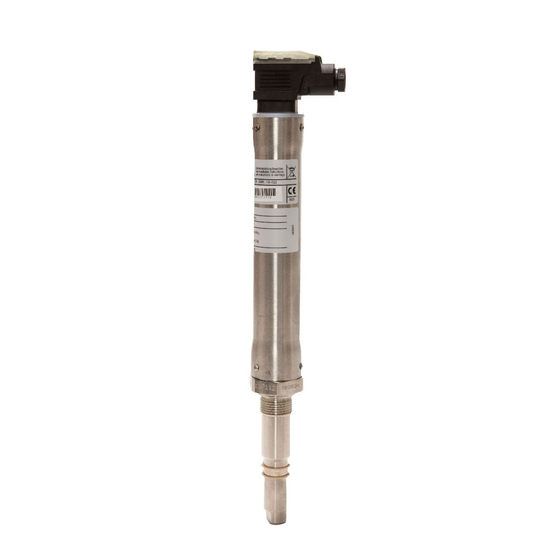
Overall View of NRG 16-51, 17-51, 19-51
Component Identification Key
Identifies the numbered components shown in the overall view diagram.
Dimensions: NRG 16-51, 17-51, 19-51 (Four-Pole Connector)
Fig. 6: Dimensions for NRG 16-51/17-51
Shows dimensional drawings for NRG 16-51 and NRG 17-51 models.
Fig. 7: Dimensions for NRG 19-51
Shows dimensional drawings for the NRG 19-51 model.
Overall View of NRG 16-51F, 17-51F, 19-51F
Component Identification Key
Identifies the numbered components shown in the overall view diagram.
Dimensions: NRG 16-51F, 17-51F, 19-51F (Aluminum Terminal Box)
Fig. 9: Dimensions for NRG 16-51F/17-51F
Shows dimensional drawings for NRG 16-51F and NRG 17-51F models.
Fig. 10: Dimensions for NRG 19-51F
Shows dimensional drawings for the NRG 19-51F model.
Installation Preparation Guidelines
Outdoor Installation Precautions
Advises on protecting equipment from environmental influences when installed outdoors.
Required Tools for Installation
Lists the necessary tools for performing the installation.
Installation Procedures and Safety Warnings
Danger: Scalding Hazard During Installation
Warns about sudden steam/water escape and advises depressurizing before removal.
Warning: Burn Hazard from Hot Electrode
Advises allowing the electrode to cool before installation or maintenance.
Attention: Potential Installation Errors
Warns against bending electrode, lagging terminal head, or using conductive paste.
Note: Protective Tube and Electrode Placement
Details requirements for protective tubes, level pots, and electrode spacing.
Installation Steps for NRG 16-51, 17-51, 19-51
Step 1: Electrode Assembly
Details the first step of installing the NRG 16-51, 17-51, 19-51 electrodes.
Key to Assembly Components
Identifies numbered components used in the installation assembly steps.
Finalizing NRG 16-51, 17-51, 19-51 Installation
Step 2: Final Installation and Sealing
Details the second step of installing the NRG 16-51, 17-51, 19-51 electrodes.
Electrical Contact Verification Procedure
Explains how to measure resistance for proper electrical contact.
Installation of NRG 16-51F, 17-51F, 19-51F
Installing with Aluminum Terminal Box
Outlines the installation process for -51F models with an aluminum terminal box.
Additional Installation Details for NRG 16-51F, 17-51F, 19-51F
Further Installation Information
Provides additional installation details for -51F electrodes.
Attention: Terminal Box Rotation Limits
Warns against rotating the terminal box beyond specified limits to avoid damage.
Installation Examples with Dimensions
Fig. 17: Protective Tube as Water Level Limiter
Shows a diagram with dimensions for using the protective tube as a water level limiter.
Fig. 18: Protective Tube for Level Control/Alarm
Shows a diagram with dimensions for using the protective tube with level control.
Level Pot Installation Examples
Fig. 19: Level Pot for External Alarm
Illustrates a level pot for external high-level alarms with dimensions.
Key to Installation Example Components
Identifies components in installation example diagrams.
Electrical Connection Procedures
NRG 16-51/17-51/19-51 (Four-Pole Connector)
Details the electrical connection for models with a four-pole connector.
Fig. 20: Four-Pole Connector Components
Diagram identifying components of the four-pole connector.
Detailed Electrical Connections
Connecting the Level Electrode
Provides instructions for connecting the level electrode, including cable type.
NRG 16-51/17-51/19-51 (Four-Pole Connector)
Step-by-step guide for connecting models with a four-pole connector.
NRG 16-51F/17-51F/19-51F (Terminal Box)
Steps for connecting models with an aluminum terminal box.
Tools for Electrical Connection
Lists tools required for performing electrical connections.
Wiring Diagrams and Connections
Master Wiring Diagram
Presents the main wiring diagram for NRG 1...-51 and NRG 1...-51F electrodes.
Fig. 22: Four-Pole Connector Wiring
Diagram showing the wiring of the level electrode with a four-pole connector.
Fig. 23: Terminal Box Wiring
Diagram showing the wiring for aluminum terminal box models.
Service, Troubleshooting, and Removal
Bringing into Service and Troubleshooting
Refers to information on bringing into service, faults and troubleshooting.
Taking the Electrode Out of Service
Provides safety warnings and steps for removing the level electrode.
Removing the NRG 1..-51 Electrode
Step-by-step instructions for removing the NRG 1..-51 electrode.
Removing the NRG 1..-51F Electrode
Step-by-step instructions for removing the NRG 1..-51F electrode.
Disposal and Equipment Returns
Product Disposal Guidelines
Instructs to dispose of electrodes according to statutory waste disposal provisions.
Returning Decontaminated Equipment
Requires draining and decontaminating equipment exposed to hazardous media.
Return Process Requirements
Specifies requirements for returning products, including return notes and declarations.
UL Component Registration
Mentions the UL registration number for the NRG 1...-51 level electrode.
Need help?
Do you have a question about the NRG 19-51 and is the answer not in the manual?
Questions and answers