
Related Manuals for GESTRA NRG 211-1


Summary of Contents for GESTRA NRG 211-1
- Page 1 Level Electrode NRG 211-1 Original Installation Instructions 810425-05 E n g l i s h...
-
Page 2: Table Of Contents
Note on the Declaration of Conformity / Manufacturer's Declaration ...........5 Technical data NRG 211-1 .............................6 Scope of supply ............................7 Name plate / marking ..........................7 Installation Dimensions NRG 211-1 ...........................8 Key .................................8 Welding standpipe ...........................9 NRG 211-1 ..............................9 Tools ...............................9 Examples of installation ........................10 Key ...............................10 Electrical connection Tools ..............................11... - Page 3 Contents - continued - Page Commissioning procedure Applying supply voltage.........................13 Checking switching functions ........................13 Key ...............................13 Troubleshooting Indication, diagnosis and remedy ......................14 Checking voltage...........................14 Checking temperature sensor .......................15 Resistance values ..........................16 Replacing electronic module .........................16 Maintenance Safety note ............................17 Checking ceramic insulator ........................17 Removing and disposing of the level electrode Removing and disposing of level electrode NRG 211 ................17...
-
Page 4: Important Notes
Important notes Usage for the intended purpose The level electrode NRG 211-1 is designed for measuring the water level in condensate lines. In conjunction with level switch NRS 2-4 the electrode can be used as max. limit switch with high level alarm. -
Page 5: Directives And Standards
For details on the conformity of our equipment according to the European Directives see our Declaration of Conformity or our Declaration of Manufacturer. The current Declaration of Conformity / Declaration of Manufacturer are available in the Internet under www.gestra.com documents or can be requested from us. -
Page 6: Technical Data
Technical data NRG 211-1 Limiting conditions for level electrode Material of flange/welding standpipe 1.5415 1.7380 1.4922 [barg] Admissible service pressure [psig] 4642 2901 4642 2901 4642 3336 [°C] Admissible service temperature [°F] 1022 Mechanical connection Special flange PN 320 with welding standpipe for pipes DN ≤ 100 with tee-piece or for pipes DN ≥... -
Page 7: Scope Of Supply
Technical data - continued - Scope of supply NRG 211-1 1 Level electrode NRG 211-1 1 Gasket with serrated faces 1 Installation manual Name plate / marking Pressure rating, flanged connec- tion, material number, protection Equipment designation Safety note PN 320 DN50 1.5415... -
Page 8: Installation
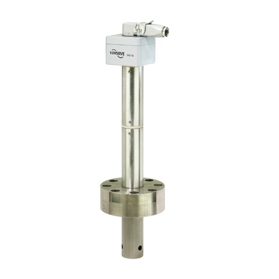
Installation Dimensions NRG 211-1 ~118 Fig. 2 ∅ 43.5 Transit protection Groove for gasket Strainer Expansion bolt Fixing screw Stuffing box Protection tube Terminal box in electronic Flange Measuring electrode Temperature sensor module... -
Page 9: Welding Standpipe
If the the level electrode is removed for inspection work make sure it is stored in a vertical position. NRG 211-1 1. Check seating surfaces. Clean end flange facings. 2. Insert joint ring into the groove of the welding standpipe. -
Page 10: Examples Of Installation
Installation - continued - Examples of installation DN ≤ 100/4" ≈12 ≈24 Fig. 3 DN > 100/4" Provided by customer Welding standpipe (GESTRA) Marking TOP... -
Page 11: Electrical Connection
Electrical connection Connection of level electrode To connect the equipment use screened multi-core control cable with a min. conductor size 0.5 mm², e. g. LiYCY 4 x 0.5 mm², max. length 500 m. Connect only one screen to the NRS 2-4. Wire terminal strip in accordance with the wiring diagram. Fig. -
Page 12: Nrv 2-30
Electrical connection - continued - NRV 2-30 Fig. 4 Wiring diagram NRG 211 NRV 2-30 Pt 1000 Fig. 5... -
Page 13: Nrv 2-30, Wiring Connecting Terminals
Commissioning procedure Note The level electrode NRG 211-1 and the level switch NRS 2-4 (MAX) form a functional unit and must only be operated and checked together. For additional information on commissioning procedures and troubleshooting refer to the installation manual of the level switch NRS 2-4. -
Page 14: Troubleshooting
Measure the voltage of the NRS 2-4 across C18/A18. LED High Level electrode defective Measure the voltage of the NRG 211-1 across Level (MAX) (insulating seal, stuffing box) terminals 2 and 3. If the voltage ≥ 9 V replace level illuminated electrode. -
Page 15: Checking Temperature Sensor
Measure the voltage of the NRS 2-4 across C18/A18. Check installation and measure the voltage of the Level electrode not submerged. NRG 211-1 across terminals 2 and 3. Check installa- tion of level electrode and, if necessary, change it. Measure the voltage of the NRS 2-4 across C16/A18 Level switch defective. -
Page 16: Resistance Values
Troubleshooting - continued - Resistance values °C Ω/°C 1000.0 1039.0 1077.9 1116.7 1155.4 1194.0 1232.4 1270.7 1308.9 1347.0 1385.0 3.85 1385.0 1422.8 1460.6 1498.2 1535.7 1573.2 1610.1 1647.6 1684.7 1721.6 1758.4 3.73 1758.4 1795.1 1831.7 1868.2 1904.6 1940.8 1977.0 2013.0 2048.8 2084.6 2120.3 3.61 2120.3 2155.8 2191.3 2226.6 2261.8 2296.9 2331.9 2366.7 2401.5 2436.1 2470.6 3.50... -
Page 17: Maintenance
Maintenance Safety note The equipment must only be installed, wired and commissioned by qualified and competent staff. Retrofitting and maintenance work must only be performed by qualified staff who - through adequate training - have achieved a recognised level of competence. Danger When loosening the level electrode steam or hot water might escape! This presents the risk of severe scalding all over the body! - Page 18 For your Notes...
- Page 19 For your Notes...
- Page 20 Agencies all over the world: www.gestra.de GESTRA AG Münchener Straße 77 28215 Bremen Germany Telefon +49 421 3503-0 Telefax +49 421 3503-393 E-mail info@de.gestra.com www.gestra.de 810425-05/01-2019cm (808456-05) · GESTRA AG · Bremen · Printed in Germany...
Need help?
Do you have a question about the NRG 211-1 and is the answer not in the manual?
Questions and answers